TW Temperature Control Valve - Spirax Sarco
TW Temperature Control Valve - Spirax Sarco
TW Temperature Control Valve - Spirax Sarco

Create successful ePaper yourself
Turn your PDF publications into a flip-book with our unique Google optimized e-Paper software.
0470050/7<br />
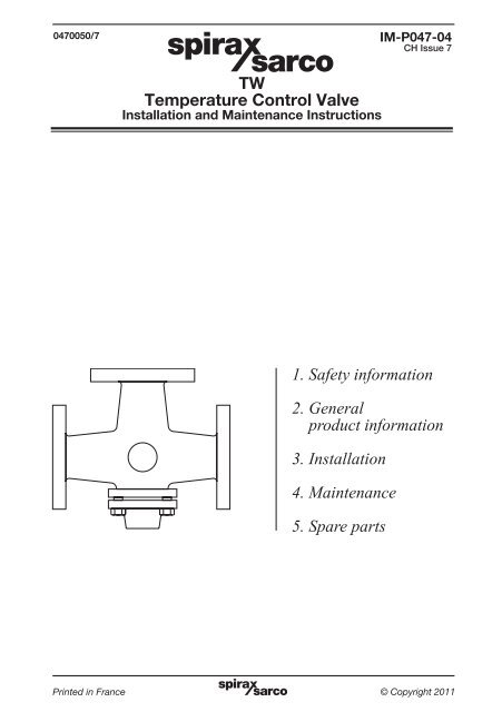
<strong>TW</strong><br />
<strong>Temperature</strong> <strong>Control</strong> <strong>Valve</strong><br />
Installation and Maintenance Instructions<br />
1. Safety information<br />
2. General<br />
product information<br />
3. Installation<br />
4. Maintenance<br />
5. Spare parts<br />
IM-P047-04<br />
CH Issue 7<br />
IM-P047-04 Printed in France CH Issue 7 © Copyright 2011<br />
1
2<br />
1. Safety information<br />
Safe operation of this product can only be guaranteed if it is properly installed,<br />
commissioned, used and maintained by qualified personnel (see Section 1.11) in<br />
compliance with the operating instructions. General installation and safety<br />
instructions for pipeline and plant construction, as well as the proper use of tools<br />
and safety equipment must also be complied with.<br />
1.1 Intended use<br />
Referring to the Installation and Maintenance Instructions, name-plate and Technical<br />
Information Sheet, check that the product is suitable for the intended use/application.<br />
The products listed below comply with the requirements of the European Pressure<br />
Equipment Directive 97/23/EC and carry the mark when so required. The products<br />
fall within the following Pressure Equipment Directive categories:<br />
Group 2<br />
Product<br />
Liquids<br />
Bronze<br />
<strong>TW</strong><br />
DN20 - DN40<br />
DN50<br />
SEP<br />
SEP<br />
Cast iron<br />
DN50<br />
DN80 - DN100<br />
SEP<br />
SEP<br />
i) The products have been specifically designed for use on water and other nonhazardous<br />
liquids which are in Group 2 of the above mentioned Pressure<br />
Equipment Directive. The products’ use on other fluids may be possible but, if<br />
this is contemplated, <strong>Spirax</strong> <strong>Sarco</strong> should be contacted to confirm the suitability<br />
of the product for the application being considered.<br />
ii) Check material suitability, pressure and temperature and their maximum and<br />
minimum values. If the maximum operating limits of the product are lower than<br />
those of the system in which it is being fitted, or if malfunction of the product<br />
could result in a dangerous overpressure or overtemperature occurrence, ensure<br />
a safety device is included in the system to prevent such over-limit situations.<br />
iii) Determine the correct installation situation and direction of fluid flow.<br />
iv) <strong>Spirax</strong> <strong>Sarco</strong> products are not intended to withstand external stresses that may<br />
be induced by any system to which they are fitted. It is the responsibility of the<br />
installer to consider these stresses and take adequate precautions to minimise them.<br />
v) Remove protection covers from all connections before installation.<br />
1.2 Access<br />
Ensure safe access and if necessary a safe working platform (suitably guarded)<br />
before attempting to work on the product. Arrange suitable lifting gear if required.<br />
1.3 Lighting<br />
Ensure adequate lighting, particularly where detailed or intricate work is required.<br />
1.4 Hazardous liquids or gases in the pipeline<br />
Consider what is in the pipeline or what may have been in the pipeline at some<br />
previous time. Consider: flammable materials, substances hazardous to health,<br />
extremes of temperature.<br />
1.5 Hazardous environment around the product<br />
Consider: explosion risk areas, lack of oxygen (e.g. tanks, pits), dangerous gases,<br />
extremes of temperature, hot surfaces, fire hazard (e.g. during welding), excessive<br />
noise, moving machinery.<br />
IM-P047-04 CH Issue 7
1.6 The system<br />
Consider the effect on the complete system of the work proposed. Will any proposed<br />
action (e.g. closing isolation valves, electrical isolation) put any other part of the system<br />
or any personnel at risk?<br />
Dangers might include isolation of vents or protective devices or the rendering<br />
ineffective of controls or alarms. Ensure isolation valves are turned on and off in a<br />
gradual way to avoid system shocks.<br />
1.7 Pressure systems<br />
Ensure that any pressure is isolated and safely vented to atmospheric pressure.<br />
Consider double isolation (double block and bleed) and the locking or labelling of<br />
closed valves. Do not assume that the system has depressurised even when the<br />
pressure gauge indicates zero.<br />
1.8 <strong>Temperature</strong><br />
Allow time for temperature to normalise after isolation to avoid danger of burns.<br />
1.9 Tools and consumables<br />
Before starting work ensure that you have suitable tools and /or consumables<br />
available. Use only genuine <strong>Spirax</strong> <strong>Sarco</strong> replacement parts.<br />
1.10 Protective clothing<br />
Consider whether you and/or others in the vicinity require any protective clothing<br />
to protect against the hazards of, for example, chemicals, high /low temperature,<br />
radiation, noise, falling objects, and dangers to eyes and face.<br />
1.11 Permits to work<br />
All work must be carried out or be supervised by a suitably competent person.<br />
Installation and operating personnel should be trained in the correct use of the<br />
product according to the Installation and Maintenance Instructions.<br />
Where a formal 'permit to work' system is in force it must be complied with. Where<br />
there is no such system, it is recommended that a responsible person should know<br />
what work is going on and, where necessary, arrange to have an assistant whose<br />
primary responsibility is safety.<br />
Post 'warning notices' if necessary.<br />
1.12 Handling<br />
Manual handling of large and /or heavy products may present a risk of injury. Lifting,<br />
pushing, pulling, carrying or supporting a load by bodily force can cause injury<br />
particularly to the back. You are advised to assess the risks taking into account the<br />
task, the individual, the load and the working environment and use the appropriate<br />
handling method depending on the circumstances of the work being done.<br />
1.13 Residual hazards<br />
In normal use the external surface of the product may be very hot. If used at the<br />
maximum permitted operating conditions the surface temperature of some products<br />
may reach temperatures of 200°C.<br />
Many products are not self-draining. Take due care when dismantling or removing<br />
the product from an installation (refer to 'Maintenance instructions').<br />
1.14 Freezing<br />
Provision must be made to protect products which are not self-draining against<br />
frost damage in environments where they may be exposed to temperatures below<br />
freezing point.<br />
IM-P047-04 CH Issue 7 3
1.15 Disposal<br />
The product is recyclable. No ecological hazard is anticipated with the disposal of this<br />
product providing due care is taken. EXCEPT;<br />
PTFE:<br />
- Can only be disposed of by approved methods, not incineration.<br />
- Keep PTFE waste in a separate container, do not mix it with other rubbish, and<br />
consign it to a landfill site.<br />
1.16 Returning products<br />
Customers and stockists are reminded that under EC Health, Safety and<br />
Environment Law, when returning products to <strong>Spirax</strong> <strong>Sarco</strong> they must provide<br />
information on any hazards and the precautions to be taken due to contamination<br />
residues or mechanical damage which may present a health, safety or<br />
environmental risk. This information must be provided in writing including<br />
Health and Safety data sheets relating to any substances identified as hazardous<br />
or potentially hazardous.<br />
4<br />
2. General product information<br />
2.1 General description<br />
The <strong>TW</strong> valve is a 3-port valve for liquid systems (including sea water) and can be used for<br />
mixing or diverting applications.<br />
Available types<br />
Bronze valves<br />
Screwed<br />
Flanged<br />
¾", 1" and 1½"<br />
DN50<br />
Cast iron valves Flanged DN50, DN80 and DN100<br />
Fig. 1 Screwed Fig. 2 Flanged<br />
2.2 Sizes and pipe connections<br />
¾", 1" and 1½" screwed BSP (BS 21 parallel) or NPT.<br />
Bronze valves DN50 standard flange EN 1092 PN25 which also meets the<br />
face-to-face dimensions of Table 16 and Table 10.<br />
Cast iron valves DN50, DN80 and DN100 standard flange EN 1092 PN16<br />
which also meets the face-to face dimensions of Table 10.<br />
IM-P047-04 CH Issue 7
2.3 Pressure/temperature limits<br />
Cast iron valves - flanged PN16<br />
<strong>Temperature</strong> °C<br />
Cast iron Bronze<br />
Body design conditions PN16 PN25<br />
Maximum design pressure 16 bar g @ 120°C 25 bar g @ 120°C<br />
Maximum design temperature 200°C @ 13.5 bar g 200°C @ 21 bar g<br />
Minimum design temperature -10°C -90°C<br />
Maximum operating temperature 200°C @ 13.5 bar g 200°C @ 21 bar g<br />
Minimum operating temperature -10°C -20°C<br />
Note: For lower operating temperatures consult <strong>Spirax</strong> <strong>Sarco</strong>.<br />
Maximum ¾", 1" and 1½" 3.4 bar 3.4 bar<br />
differential<br />
pressure DN50, DN80 and DN100 2.7 bar 2.7 bar<br />
Designed for a maximum<br />
cold hydraulic test pressure of:<br />
Pressure bar g<br />
Bronze valves - screwed and flanged PN25<br />
<strong>Temperature</strong> °C<br />
Pressure bar g<br />
The product must not be used in this region.<br />
24 bar g 37.5 bar g<br />
Maximum test pressure 16 bar g 25 bar g<br />
Leakage rate 1% of full Kv (see Section 2.4, Kv values)<br />
IM-P047-04 CH Issue 7 5
2.4 Kv values<br />
Size ¾" 1" 1½" DN50 DN80 DN100<br />
Kv 4.64 8.96 20.29 41.20 97.85 118.45<br />
For conversion: Cv (UK) = Kv x 0.97 Cv (US) = Kv x 1.17<br />
2.5 Sizing For water see TI-GCM-09.<br />
2.6 Materials<br />
No. Part Material<br />
1 Body<br />
6<br />
Bronze CC 491 KM<br />
Cast iron EN GJL 250<br />
2 Piston Bronze BS 1400 LG2<br />
3 Piston sealing ring Carbon impregnated PTFE<br />
4 Stem<br />
DN20 - DN40 Brass BS 2874 CZ 121<br />
DN50 - DN100 Bronze<br />
5 Spacer piece Bronze BS 2874 PB 102<br />
6 Lock-nut Bronze BS 2874 PB 102<br />
7 Return spring Stainless steel BS 2056 302 S26<br />
8 Return spring cover<br />
9 Cover<br />
DN20 - DN40 Brass BS 2874 CZ 121<br />
DN50 - DN100 Bronze BS 2874 BP 102<br />
Bronze CC 491 KM<br />
Cast iron EN GJL 250<br />
10 Cover sealing ring Reinforced exfoliated graphite<br />
11 Bonnet<br />
DN20 - DN25 Brass CW 617N<br />
DN40 - DN100 Bronze CC 491 KM<br />
12 Bonnet gasket Nickel reinforced exfoliated graphite<br />
13<br />
Cover studs Steel UNF x 1 " (35 mm) BS 2693 / 1<br />
Cover nuts Steel BS 1768 / R<br />
14 Back seal Bronze BS 2874 PB 102<br />
15 Split pin Phosphor bronze<br />
X<br />
3<br />
11<br />
O<br />
Fig. 3 Bronze valve Fig. 4 Cast iron valve<br />
Z<br />
8<br />
7<br />
2<br />
1<br />
12<br />
4<br />
5<br />
4<br />
7<br />
13<br />
9<br />
12<br />
X<br />
O<br />
Z<br />
6, 15<br />
IM-P047-04 CH Issue 7<br />
1<br />
3<br />
2<br />
10<br />
8<br />
14<br />
11
2.7 Dimensions/weights (approximate) in mm and kg<br />
Bronze screwed<br />
Size A B C Weight<br />
¾" 97 54 58 1.2<br />
1" 114 57 61 1.9<br />
1½" 151 70 76 3.8<br />
B<br />
C<br />
A<br />
Fig. 5 Screwed<br />
Bronze flanged PN25<br />
Size A B C Weight<br />
DN50 201 144 133 15.0<br />
A<br />
Fig. 6 Flanged<br />
Cast iron flanged PN16<br />
Size A B C Weight<br />
DN50 219 153 133 13.7<br />
DN80 250 176 135 25.0<br />
DN100 351 151 140 32.0<br />
IM-P047-04 CH Issue 7 7<br />
B<br />
C
8<br />
3. Installation<br />
Note: Before actioning any installation observe the 'Safety information' in Section 1.<br />
3.1 Important information<br />
<strong>TW</strong> valves are for use only with SA control systems or electonic actuators of the following types:-<br />
<strong>Valve</strong> size <strong>Control</strong> system/actuator<br />
DN20 and DN25<br />
DN40 and DN50<br />
DN80 and DN100<br />
SA controls SA121, SA122, SA123 and SA128<br />
EL actuators EL3501, EL3502 and EL312 + EL3808 linkage kit<br />
SA controls SA121 and SA123<br />
EL actuators EL3501, EL3502 and EL3512 + EL3808 linkage kit<br />
SA contols SA1219 and SA1239<br />
EL actuators EL3501, EL3502 and EL3512 + EL3809 linkage kit<br />
The 3 valve ports on the <strong>TW</strong> valve are marked X, Z and O (see Figures 3 and 4). The valve should<br />
always be fitted in a horizontal pipeline with the actuator vertically below the line as shown in<br />
the installation layout diagrams, Section 3.2.<br />
Isolating valves should be fitted to enable maintenance work (should it become necessary) to<br />
be carried out without emptying down the plant.<br />
It is important that line stresses such as can be caused by expansion or inadequate supporting<br />
of the pipeline are not imposed on the valve body.<br />
It is advisable to protect the valve by fitting a strainer on each inlet pipeline close to the valve.<br />
3.2 Installation layout diagrams - some typical examples<br />
Important note: Irrespective of whether the valve is mixing or diverting, heating or cooling,<br />
Port 'O' is always open. Port 'X' closes with a rise in temperature (SA control system) or an<br />
extension of the actuator spindle (EL control).<br />
Cold supply Hot supply<br />
Sensor<br />
Fig. 7 As a blender for process hot water<br />
O<br />
Z X<br />
Strainer<br />
Blended flow<br />
When the <strong>TW</strong> valve is used in this way it is essential<br />
that the pressure of the supplies be equal.<br />
IM-P047-04 CH Issue 7
Balancing valve<br />
Fig. 8 As a diversion valve - Heating<br />
Balancing valve<br />
Fig. 9 As a diversion valve - Cooling - Brine or chilled water<br />
Engine<br />
O<br />
Z<br />
Actuator<br />
O<br />
Actuator<br />
X<br />
X Z<br />
Air eliminator<br />
Balancing<br />
valve<br />
Pump<br />
Strainer<br />
Heater battery<br />
Heater battery<br />
Strainer<br />
Fig. 10 As a diversion valve - Cooling - Diesel engines or compressors<br />
Air flow<br />
Air flow<br />
IM-P047-04 CH Issue 7 9<br />
O<br />
X Z<br />
Isolating<br />
valve<br />
Brine or<br />
chilled water supply<br />
Isolating<br />
valve<br />
Sensor<br />
Hot water flow<br />
Sensor<br />
Sensor<br />
Cooler
10<br />
4. Maintenance<br />
Note: Before actioning any maintenance observe the 'Safety information' in Section 1.<br />
4.1 General note<br />
The strainers, if fitted as recommended, should be cleaned at regular intervals to ensure that<br />
the flow to the valve is clear and unrestricted.<br />
4.2 Warning<br />
Before attempting to carry out any repairs make sure that the valve is fully isolated and<br />
disconnect the actuator coupling from the valve at the union.<br />
Always renew the parts in complete assemblies or sets as listed in Section 5, 'Spare parts' and<br />
make sure that all joint faces are clean.<br />
Use the new gasket provided with the spare parts and lightly coat with a suitable jointing paste.<br />
4.3 How to replace the piston sealing ring (refer to Figure 11)<br />
(Piston set and piston sealing ring set):<br />
1. Unscrew the bonnet (11) or undo the 4 cover nuts (13) and withdawer the complete piston<br />
and bonnet assembly.<br />
2. Remove the piston sealing ring (3) from the recess in the body and clean the recess.<br />
3. The replacement ring is of carbon impregnated PTFE with a steel backing ring and is a<br />
replacement for all previous types of ring.<br />
4. The ring should be fitted so that the chamferred edge X is facing the cover of the valve.<br />
5. Allow the ends of the ring to overlap as Y. Place an end into the recess in the body and feed<br />
the ring into place by pressing outwards.<br />
6. Using the new gasket (10) or (12) lightly coated with jointing paste fit the new piston and<br />
bonnet assembly into the body taking care not to damage the piston sealing ring (3).<br />
7. Reconnect the actuator to the bonnet.<br />
Piston set (DN50 - DN100)<br />
Firstly follow steps 1 - 5 above then:<br />
8. Remove the bonnet complete with gasket (10) and back seal.<br />
9. With the stem push rod held in a box spanner 16 mm (0.6") A/F remove the split pin (15),<br />
lock-nut (6) and spacer (5). Remove the piston (2) and replace with the new one, compressing<br />
the return spring by using the box spanner on the stem enabling the new lock-nut (6),<br />
spacer (5) and split pin (15) to be fitted into place.<br />
10. Reassemble as Steps (6) and (7) above.<br />
IM-P047-04 CH Issue 7
5. Spare parts<br />
The spare parts are shown in heavy outline. Parts drawn in broken line are not available as spares.<br />
Available spares<br />
Piston sealing ring set<br />
¾" to 1½"<br />
DN50 to DN100<br />
3, 7, 12<br />
3, 10, 12<br />
Piston set<br />
¾" to 1½"<br />
DN50 to DN100<br />
2, 3, 7, 12<br />
2, 3, 5, 6, 7, 12, 15<br />
Set of cover studs and nuts 13<br />
How to order spares<br />
Always order spares by using the description given in the column headed 'Available spares' and<br />
state the size and type of valve.<br />
Example: 1 - Piston set for a DN50 <strong>Spirax</strong> <strong>Sarco</strong> <strong>TW</strong> 3-port valve.<br />
Fig. 11<br />
3<br />
7<br />
2<br />
12<br />
11<br />
<strong>Valve</strong> size<br />
¾" - 1½"<br />
<strong>Valve</strong> size<br />
DN50 - DN100<br />
Detail of<br />
piston ring<br />
X<br />
IM-P047-04 CH Issue 7 11<br />
Y<br />
15<br />
6<br />
5<br />
3<br />
2<br />
13<br />
10<br />
11<br />
13<br />
12
12<br />
IM-P047-04 CH Issue 7