AV13 Air Vent for Steam Systems - Spirax Sarco
AV13 Air Vent for Steam Systems - Spirax Sarco
AV13 Air Vent for Steam Systems - Spirax Sarco

You also want an ePaper? Increase the reach of your titles
YUMPU automatically turns print PDFs into web optimized ePapers that Google loves.
1232550/7<br />
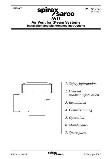
<strong>AV13</strong><br />
<strong>Air</strong> <strong>Vent</strong> <strong>for</strong> <strong>Steam</strong> <strong>Systems</strong><br />
Installation and Maintenance Instructions<br />
1. Safety in<strong>for</strong>mation<br />
2. General<br />
product in<strong>for</strong>mation<br />
3. Installation<br />
4. Commissioning<br />
5. Operation<br />
6. Maintenance<br />
7. Spare parts<br />
IM-P010-07<br />
ST Issue 7<br />
IM-P010-07 Printed in the ST UK Issue 7 © Copyright 2007 1
2<br />
1. Safety in<strong>for</strong>mation<br />
Safe operation of this unit can only be guaranteed if it is properly installed,<br />
commissioned, used and maintained by a qualified personnel (see Section 1.11)<br />
in compliance with the operating instructions. General installation and safety<br />
instructions <strong>for</strong> pipeline and plant construction, as well as the proper use of tools<br />
and safety equipment must also be complied with.<br />
1.1 Intended use<br />
Referring to the Installation and Maintenance Instructions, name-plate and<br />
Technical In<strong>for</strong>mation Sheet, check that the product is suitable <strong>for</strong> the intended<br />
use/application. This product complies with the requirements of the European<br />
Pressure Equipment Directive 97/23/EC and falls within category SEP and there<strong>for</strong>e<br />
does not carry the mark:<br />
Group 2 Group 2<br />
Product gases liquids<br />
<strong>AV13</strong> SEP SEP<br />
i) The product has been specifically designed <strong>for</strong> use on steam, air or water/<br />
condensate which are in Group 2 of the above mentioned Pressure Equipment<br />
Directive. The products use on other fluids may be possible but, if this is<br />
contemplated, <strong>Spirax</strong> <strong>Sarco</strong> should be contacted to confirm the suitability of<br />
the product <strong>for</strong> the application being considered.<br />
ii) Check material suitability, pressure and temperature and their maximum and<br />
minimum values. If the maximum operating limits of the product are lower than<br />
those of the system in which it is being fitted, or if malfunction of the product<br />
could result in a dangerous overpressure or overtemperature occurrence,<br />
ensure a safety device is included in the system to prevent such over-limit<br />
situations.<br />
iii) Determine the correct installation situation and direction of fluid flow.<br />
iv) <strong>Spirax</strong> <strong>Sarco</strong> products are not intended to withstand external stresses that may<br />
beinduced by any system to which they are fitted. It is the responsibility of the<br />
installer to consider these stresses and take adequate precautions to minimise<br />
them.<br />
v) Remove protection covers from all connections and protective film from all<br />
name-plates, where appropriate, be<strong>for</strong>e installation on steam or other high<br />
temperature applications.<br />
1.2 Access<br />
Ensure safe access and if necessary a safe working plat<strong>for</strong>m (suitably guarded)<br />
be<strong>for</strong>e attempting to work on the product. Arrange suitable lifting gear if required.<br />
1.3 Lighting<br />
Ensure adequate lighting, particularly where detailed or intricate work is required.<br />
1.4 Hazardous liquids or gases in the pipeline<br />
Consider what is in the pipeline or what may have been in the pipeline at some<br />
previous time. Consider; flammable materials, substances hazardous to health,<br />
extremes of temperature.<br />
IM-P010-07 ST Issue 7
1.5 Hazardous environment around the product<br />
Consider; explosion risk areas, lack of oxygen (e.g. tanks, pits), dangerous gases,<br />
extremes of temperature, hot surfaces, fire hazard (e.g. during welding), excessive<br />
noise, moving machinery.<br />
1.6 The system<br />
Consider the effect on the complete system of the work proposed. Will any<br />
proposed action (e.g. closing isolation valves, electrical isolation) put any other<br />
part of the system or any personnel at risk?<br />
Dangers might include isolation of vents or protective devices or the rendering<br />
ineffective of controls or alarms. Ensure isolation valves are turned on and off in<br />
a gradual way to avoid system shocks.<br />
1.7 Pressure systems<br />
Ensure that any pressure is isolated and safely vented to atmospheric pressure.<br />
Consider double isolation (double block and bleed) and the locking or labelling of<br />
closed valves. Do not assume that the system has depressurised even when the<br />
pressure gauge indicates zero.<br />
1.8 Temperature<br />
Allow time <strong>for</strong> temperature to normalise after isolation to avoid danger of burns.<br />
If the 'O' ring has been subjected to a temperature approaching 315°C<br />
(599°F) or higher, it may have decomposed and <strong>for</strong>med hydroflouric acid. Avoid skin<br />
contact and inhalation of any fumes as the acid will cause deep skin burns and<br />
damage the respiratory system.<br />
1.9 Tools and consumables<br />
Be<strong>for</strong>e starting work ensure that you have suitable tools and/or consumables<br />
available. Use only genuine <strong>Spirax</strong> <strong>Sarco</strong> replacement parts.<br />
1.10 Protective clothing<br />
Consider whether any protective clothing is required by yourself and/or others in<br />
the vicinity to protect against the hazards of, <strong>for</strong> example, chemicals, high/low<br />
temperature, radiation, noise, falling objects, and dangers to eyes and face.<br />
1.11 Permits to work<br />
All work must be carried out or be supervised by a suitably competent person.<br />
Installation and operating personnel should be trained in the correct use of the<br />
product according to these instructions.<br />
Where a <strong>for</strong>mal 'permit to work' system is in <strong>for</strong>ce it must be complied with. Where<br />
there is no such system, it is recommended that a responsible person should know<br />
what work is going on and, where necessary, arrange to have an assistant whose<br />
primary responsibility is safety.<br />
Post 'warning notices' if necessary.<br />
IM-P010-07 ST Issue 7 3
1.12 Handling<br />
Manual handling of <strong>Spirax</strong>-<strong>Sarco</strong> products may present a risk of injury. Lifting,<br />
pushing, pulling, carrying or supporting a load by bodily <strong>for</strong>ce can cause injury<br />
particularly to the back. You are advised to assess the risks taking into account the<br />
task, the individual, the load and the working environment and use the appropriate<br />
handling method depending on the circumstances of the work being done.<br />
1.13 Residual hazards<br />
In normal use the external surface of the product may be very hot. If used at the<br />
maximum permitted operating conditions the surface temperature of some products<br />
may reach temperatures in excess of 250°C (482°F).<br />
This product is not self-draining. Take due care when dismantling or removing<br />
the product from an installation (refer to 'Maintenance instructions').<br />
1.14 Freezing<br />
Provision must be made to protect products which are not self-draining against<br />
frost damage in environments where they may be exposed to temperatures below<br />
freezing point.<br />
1.15 Disposal<br />
Apart from the 'O' ring this product is recyclable and no ecological hazard is<br />
anticipated with its disposal providing due care is taken.<br />
If the recycling process involves a temperature approaching 315°C caution<br />
is advised regarding decomposition of the fluorocarbon rubber 'O' ring (see<br />
Section 1.8).<br />
'O' ring:<br />
- Can be landfilled, when in compliance with National and Local regulations.<br />
- Can be incinerated, but a scrubber must be used to remove Hydrogen Fluoride,<br />
which is evolved from the product and with compliance to National and Local<br />
regulations.<br />
- Is insoluble in aquatic media.<br />
1.16 Returning products<br />
Customers and stockists are reminded that under UK and EC Health, Safety and<br />
Environment Law, when returning products to <strong>Spirax</strong> <strong>Sarco</strong> they must provide<br />
in<strong>for</strong>mation on any hazards and the precautions to be taken due to contamination<br />
residues or mechanical damage which may present a health, safety or<br />
environmental risk. This in<strong>for</strong>mation must be provided in writing including<br />
Health and safety data sheets relating to any substances identified as hazardous<br />
or potentially hazardous.<br />
4<br />
IM-P010-07 ST Issue 7
2. General product in<strong>for</strong>mation<br />
2.1 Description<br />
The <strong>AV13</strong> is a brass bodied maintainable balanced pressure thermostatic air vent <strong>for</strong><br />
steam systems.<br />
Standards<br />
The product fully complies with the requirements of the European Pressure Equipment<br />
Directive 97 / 23 / EC.<br />
Certification<br />
The product is available with a manufacturers' Typical Test Report. Note: All certification/<br />
inspection requirements must be stated at the time of order placement.<br />
Note: For further product data see the Technical In<strong>for</strong>mation Sheet TI-P010-02.<br />
2.2 Sizes and pipe connections<br />
", ½" and ¾" screwed BSP (BS 21 parallel) or NPT.<br />
Fig. 1<br />
IM-P010-07 ST Issue 7 5
2.3 Pressure/temperature limits<br />
6<br />
The product should not be used in this region or beyond its operating<br />
range as damage to the internals may occur.<br />
Temperature °C<br />
� �� �� �� �� ��� ��� ��� ��� ��� ��� ���<br />
���<br />
���<br />
���<br />
���<br />
��<br />
Pressure psi g<br />
<strong>Steam</strong><br />
saturation<br />
curve<br />
� � � � �� ��<br />
� � �� ��<br />
Pressure bar g<br />
The product must not be used in this region.<br />
Body design conditions PN16<br />
PMA Maximum allowable pressure 16 bar g @ 120°C (232 psi g @ 248°F)<br />
TMA Maximum allowable temperature 250°C @ 7 bar g (482°F @ 102 psi g)<br />
Minimum allowable temperature -20°C (-4°F)<br />
PMO Maximum operating pressure 13 bar g @ 220°C (189 psi g @ 428 psi g)<br />
TMO Maximum operating temperature 250°C @ 7 bar g (482°F @ 102 psi g)<br />
Minimum operating temperature 0°C (32°F)<br />
Designed <strong>for</strong> a maximum cold hydraulic test pressure of: 24 bar g (348 psi g)<br />
���<br />
���<br />
���<br />
���<br />
Temperature °F<br />
IM-P010-07 ST Issue 7
3. Installation<br />
Note: Be<strong>for</strong>e actioning any installation observe the 'Safety in<strong>for</strong>mation' in Section 1.<br />
Referring to the Installation and Maintenance Instructions, name-plate and Technical<br />
In<strong>for</strong>mation Sheet, check that the product is suitable <strong>for</strong> the intended installation:<br />
3.1 Check materials, pressure and temperature and their maximum values. If the maximum<br />
operating limit of the product is lower than that of the system in which it is being fitted,<br />
ensure that a safety device is included in the system to prevent overpressurisation.<br />
3.2 Determine the correct installation situation and the direction of fluid flow.<br />
3.3 Remove protection covers from all connections and protective film from all<br />
name-plates, where appropriate, be<strong>for</strong>e installation on steam or other high temperature<br />
applications.<br />
3.4 The <strong>AV13</strong> should be installed with the capsule in a horizontal plane with the cap at<br />
the top and be positioned at the highest point of the main, or plant, where the air<br />
collects. For maximum removal of the air, the discharge should be as free as<br />
possible and piped to a safe location.<br />
3.5 Isolation valves must be installed to allow <strong>for</strong> safe maintenance and trap replacement.<br />
3.6 Open isolation valves slowly until normal operating conditions are achieved.<br />
3.7 Check <strong>for</strong> leaks and correct operation.<br />
3.8 Ensure adequate space is left to remove the cover from the body <strong>for</strong> maintenance.<br />
Minimum withdrawal distance <strong>for</strong> the cover is 55 mm.<br />
Note: If the <strong>AV13</strong> is to discharge to atmosphere ensure it is a safe place, the discharging<br />
fluid may be at a temperature of 100°C (212°F).<br />
4. Commissioning<br />
After installation or maintenance ensure that the system is fully functional. Carry out tests<br />
on any alarms or protective devices.<br />
5. Operation<br />
The operating element is a capsule containing a small quantity of a special liquid with a<br />
boiling point below that of water. In the cold conditions that exist at start-up, the capsule<br />
is relaxed. The valve is off its seat and is wide open, allowing unrestricted removal of air.<br />
This is a feature of all balanced pressure traps and explains why they are well suited to air<br />
venting.<br />
IM-P010-07 ST Issue 7 7
8<br />
6. Maintenance<br />
Note: Be<strong>for</strong>e actioning any maintenance programme observe<br />
the 'Safety in<strong>for</strong>mation' in Section 1.<br />
6.1 General in<strong>for</strong>mation<br />
Be<strong>for</strong>e undertaking any maintenance on the <strong>AV13</strong> it must be isolated from the supply<br />
line and return line and any pressure allowed to safely normalise to atmosphere. The <strong>AV13</strong><br />
should then be allowed to cool. When reassembling, ensure that all joint faces are clean.<br />
Maintenance can be completed with the <strong>AV13</strong> in the pipeline, once the safety procedures<br />
have been observed. It is recommended that new gaskets and spares are used whenever<br />
maintenance is undertaken. Ensure that the correct tools and necessary protective<br />
equipment are used at all times. When maintenance is complete open the isolation valves<br />
slowly and check <strong>for</strong> leaks.<br />
6.2 How to fit a new capsule and seat:<br />
- Remove the cap (2) using a spanner.<br />
- Lift out the spring (5), capsule (4) and spacer plate (6).<br />
- Unscrew the valve seat (7).<br />
- Remove the seat gasket (8).<br />
- Fit a new seat gasket (8).<br />
- Screw in a new valve seat (7). Use a small amount of anti-seize compound on the threads<br />
and tighten to the recommended torque (see Table 1).<br />
- Drop in the new spacer plate (6) ensuring it is located centrally on the valve seat (7).<br />
Note: Early spacer plates are unidirectional and must be fitted with the highest points<br />
uppermost (see Figure 2). This does not apply to later models, which can be fitted either<br />
way up.<br />
- Fit new capsule (4) and spring (5) ensuring that the conical spring is positioned with the<br />
narrow end pointing downwards in contact with the capsule.<br />
- Screw on the cap (2) using a new 'O' ring (3) assembled into the groove in the top of the<br />
cap, or in older models using a new gasket. Note: The spares pack contains 2 sizes of<br />
'O' ring, use of the correct 'O' ring is explained in the note contaned within the package.<br />
Tighten to the recommended torque (see Table 1).<br />
Fig. 2 Old style spacer plate<br />
Table 1 Recommended tightening torques<br />
or<br />
Item no. Part N m (lbf ft)<br />
mm<br />
2<br />
Gasket 50 A/F 90 - 100 (66 - 74)<br />
'O' ring 50 A/F 50 - 60 (37 - 44)<br />
7 Seat 17 A/F 35 - 40 (26 - 29)<br />
IM-P010-07 ST Issue 7
2<br />
Fig. 3<br />
IM-P010-07 ST Issue 7 9<br />
3<br />
5<br />
4<br />
6<br />
7<br />
8
10<br />
7. Spare parts<br />
The spare parts available are shown in solid outline. Parts drawn in broken line are not<br />
supplied as spares.<br />
Available spares<br />
Maintenance kit 3, 4, 5, 6, 7, 8<br />
Cap gasket (earlier models) (packet of 3) 3<br />
'O' ring (current models) (packet of 3) 3<br />
Note: Earlier models were fitted with conventional gaskets. Current models are fitted with<br />
an 'O' ring to seal the cap. There are two types of 'O' ring. The 'O' ring used is dependent on<br />
the body type.<br />
How to order spares<br />
Always order spares by using the description given in the column headed 'Available spares'<br />
and state the size and type of air vent.<br />
Example: 1 - Capsule and seat assembly <strong>for</strong> a ½" <strong>Spirax</strong> <strong>Sarco</strong> <strong>AV13</strong> balanced pressure<br />
thermostatic air vent.<br />
2<br />
Fig. 4<br />
IM-P010-07 ST Issue 7<br />
3<br />
5<br />
4<br />
6<br />
7<br />
8
IM-P010-07 ST Issue 7 11
12<br />
IM-P010-07 ST Issue 7