Pyrojector II
Pyrojector II
Pyrojector II
Create successful ePaper yourself
Turn your PDF publications into a flip-book with our unique Google optimized e-Paper software.
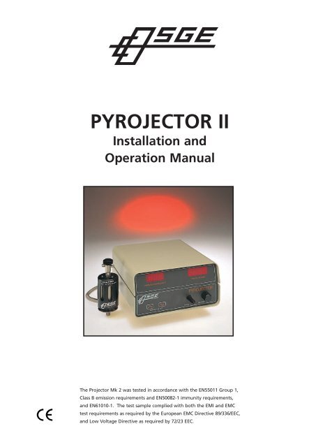
PYROJECTOR <strong>II</strong><br />
Installation and<br />
Operation Manual<br />
The Projector Mk 2 was tested in accordance with the EN55011 Group 1,<br />
Class B emission requirements and EN50082-1 immunity requirements,<br />
and EN61010-1. The test sample complied with both the EMI and EMC<br />
test requirements as required by the European EMC Directive 89/336/EEC,<br />
and Low Voltage Directive as required by 72/23 EEC.
1.0 WARRANTY<br />
2.0 INTRODUCTION<br />
3.0 INSTALLATION<br />
3.1 FURNACE ASSEMBLY<br />
3.2 INSTALLATION ON THE GC INJECTOR<br />
3.3 MAIN CONTROL MODULE<br />
3.3.1 Main Voltage Selection<br />
3.3.2 Gas Connections<br />
3.3.2.1 Septum Injection Head and Pelletizer Injection Head<br />
3.3.2.2 Septumless Injection Head<br />
3.3.3 Furnace Power Cable<br />
4.0 OPERATION<br />
4.1 FRONT PANEL CONTROLS<br />
4.2 REAR PANEL CONNECTIONS<br />
4.3 GAS FLOWS<br />
4.4 TEMPERATURE SETTING<br />
4.5 SAMPLE INJECTION<br />
4.5.1 Conventional Septum Injection<br />
4.5.1.1 Low Viscosity Liquid Samples<br />
4.5.1.2 High Viscosity Liquid Samples<br />
4.5.1.3 Solid Samples<br />
4.5.1.4 Pelletizer P-1<br />
4.5.2 Septumless Sample Injection<br />
4.5.2.1 Operation of Septumless Injector<br />
4.5.3 Pelletizer Injection<br />
4.5.3.1 Operation of Pellitizer Injector<br />
4.6 FURNACE REMOVAL AND CLEANING<br />
4.6.1 Quartz Furnace Liner Removal<br />
4.6.2 Quartz Furnace Liner Cleaning<br />
4.6.3 Quartz Furnace Liner Replacement<br />
4.7 SYRINGE MAINTENANCE<br />
4.7.1 PTFE Seal Replacement<br />
4.7.2 Plunger Replacement<br />
4.8 DIGITAL PRESSURE METER<br />
5.0 OPERATING HINTS<br />
5.1 TEMPERATURE PROFILES<br />
5.2 CRYOGENIC OPERATION<br />
6.0 SERVICE<br />
6.1 PACKING & REORDER LIST<br />
6.2 FAULT FINDING<br />
6.2.1 Electrical Faults<br />
6.3 FURNACE REPLACEMENT<br />
6.4 THERMOCOUPLE REPLACEMENT<br />
PYROJECTOR <strong>II</strong><br />
7.0 PYROJECTOR <strong>II</strong> – GC INJECTOR ADAPTORS<br />
8.0 ELECTRICAL WIRING DIAGRAM<br />
9.0 PNEUMATIC CONNECTIONS DIAGRAM
The <strong>Pyrojector</strong> <strong>II</strong> control module is guaranteed against faults in materials and workmanship<br />
for a period of twelve months from the date of invoice.<br />
The <strong>Pyrojector</strong> <strong>II</strong> furnace assembly and components are subject to three months warranty<br />
from the date of invoice.<br />
This warranty implies free repair and/or<br />
replacement of defective goods, only upon<br />
proper written proof and (where authorized)<br />
return of the defective product.<br />
This unit has been designed to fulfill the<br />
purpose of pyrolysis of small samples for gas<br />
chromatography. This warranty is void if the<br />
instrument is used for any unrelated purposes.<br />
SGE reserves the right to refuse free service<br />
under warranty on any unit that has been<br />
abused or tampered with in any way.<br />
No other warranty or representation is<br />
expressed or implied by SGE for its products<br />
with respect to merchantability, fitness for any<br />
particular use or purpose or any other matter.<br />
SGE shall not, under any circumstances, be<br />
liable for any incidental, consequential, or<br />
compensatory damages arising from use of, or<br />
in conjunction with, its products. The<br />
maximum liability for breach of warranty shall<br />
be the invoice price of said products. SGE<br />
acknowledges that there are many service<br />
engineers in the field who have expertise to<br />
service the <strong>Pyrojector</strong> <strong>II</strong> and to assist them, we<br />
have enclosed the necessary data in this<br />
manual. To protect your interest however, we<br />
respectfully suggest that any failures be<br />
attended to by SGE service personnel or by<br />
SGE authorized service people.<br />
Note: SGE does not advocate the use of<br />
hydrogen with this accessory due to potential<br />
problems associated with its inflammable<br />
nature.<br />
1.0 WARRANTY<br />
Pg 1
Pyrolysis Gas Chromatography is a specialized<br />
sample introduction technique in which a high<br />
molecular weight sample is heated rapidly to<br />
pyrolysing temperatures up to 900˚C in a nonoxidizing<br />
atmosphere.<br />
Under these conditions the high molecular<br />
weight sample will fragment or "unzip" into<br />
lower molecular weight fragments, which can<br />
be chromatographed in the conventional<br />
manner.<br />
The result is normally a complex GC<br />
chromatogram (or pyrogram), whose profile is<br />
characteristic of the particular parent sample<br />
under the particular pyrolysis conditions. This<br />
technique is especially valuable for the rapid<br />
identification of samples, which are not<br />
chromatographable by conventional GC<br />
techniques.<br />
Examples of some of the areas of application<br />
are:<br />
Identification of synthetic polymers<br />
Bacteriological identification<br />
Characterization of natural polymers<br />
Forensic applications such as fiber or paint<br />
cross-matching<br />
There are two major types of pyrolysis units:<br />
1. Continuous–mode pyrolyser<br />
Essentially an on-line inlet furnace which is<br />
continuously heated to the desired pyrolysis<br />
temperature. SGE’s <strong>Pyrojector</strong> <strong>II</strong> is an example<br />
of this type of system. The sample is injected<br />
directly into the furnace using special types of<br />
syringes. The advantages of this system are<br />
that the pyrolysis conditions can be controlled<br />
very accurately and reproducible sample sizes<br />
are more easily achieved.<br />
2. Pulse-mode pyrolyser<br />
The sample is placed directly onto the cooled<br />
element at the pyrolysis probe tip. The probe is<br />
then inserted and sealed into the inlet and the<br />
2.0 INTRODUCTION<br />
element is rapidly heated (at a uniform rate), to<br />
the pyrolysis temperature range. Pulsed systems<br />
have the disadvantage that the exact<br />
temperature is not measurable and pyrograms<br />
are more hardware dependent. In addition,<br />
small sample sizes are more difficult to control.<br />
General Considerations<br />
The pyrolysis profile obtained is a function of<br />
the individual type and design of the pyrolyser<br />
and the gas chromatograph conditions. There<br />
are several factors that will affect the pyrogram<br />
profile and reproducibility. Among these are:<br />
Temperature control: Dependent on pyrolyser<br />
design and hardware considerations. (Furnace<br />
ID, length of heated zone, etc).<br />
Pyrolysis furnace gas flow: The gas flow rate<br />
determines the residence time of the sample<br />
pyrolysis products in the furnace and may<br />
affect secondary pyrolysis.<br />
Sample size: Best results are achieved with<br />
very small sample sizes, which minimize<br />
the occurrence of secondary reactions.<br />
Pyrolyser/GC Interface: Choice of the GC inlet<br />
type is important, primarily due to factors such<br />
as discrimination and the width and size of the<br />
sample band as it is introduced into the<br />
column.<br />
SGE’s <strong>Pyrojector</strong> <strong>II</strong> has been developed with all<br />
these considerations in mind to give<br />
reproducible pyrolysis.<br />
Pg 2
3.1 FURNACE ASSEMBLY<br />
For shipment, the furnace is packed in a number of<br />
pieces and requires assembly. Refer to Figure 1 for<br />
the diagram of the furnace assembly.<br />
Insert a plug of quartz wool (6) into one of the<br />
quartz furnace liners (3) to form a bed<br />
approximately 5mm thick. This plug should be<br />
positioned to be in the centre of the furnace once<br />
installed.<br />
This plug of quartz wool is required to prevent the<br />
sample from passing through the furnace into the<br />
cooler, lower part of the tube without undergoing<br />
satisfactory pyrolysis. The quartz wool is also of use<br />
to prevent particulate matter falling down into the<br />
transfer line, resulting in blockages.<br />
Lay the furnace on its side and slide the quartz<br />
furnace liner packed with quartz wool into the<br />
furnace. (The liners are symmetrical and can be<br />
inserted either way).<br />
Fit a 1/4" graphite ferrule with 6mm ID (11) onto<br />
the outlet end of the quartz furnace liner (3). The<br />
tapered end of the ferrule should face into the<br />
baseplate assembly (7). (See Figure 1)<br />
Insert the transfer tube (10) into the GC instrument<br />
specific adapter (8) and screw the adapter onto the<br />
baseplate to lock the quartz furnace liner into<br />
position.<br />
3.0 INSTALLATION<br />
Before commencing installation, please check all items listed in Section 6.1 (Page 12) have been<br />
supplied. Contact your local SGE office or supplier if any parts are missing.<br />
The <strong>Pyrojector</strong> <strong>II</strong> is supplied with three different<br />
sample injection heads:<br />
• Septum injection head<br />
• Septumless injection head<br />
• Pelletizer injection head<br />
See section 4.5 on page 7 for a guide to<br />
selecting the most suitable injection head for<br />
your application.<br />
(It is essential that the quartz furnace liner is fully<br />
located into the end of the transfer tube end fitting<br />
to avoid creating a large dead volume.) Tighten the<br />
adapter finger-tight, then one half of a turn with a<br />
spanner.<br />
Slide a 1/4" graphite ferrule with 6mm ID (11),<br />
taper first over the quartz liner at the top of the<br />
furnace and screw on the selected sample injection<br />
head. Finger tighten at first and then a further half<br />
turn with a spanner.<br />
Figure 1<br />
Carrier Inlet<br />
'C'<br />
Spacer<br />
Spacer<br />
11. OGF4-06.<br />
Graphite Ferrule<br />
Existing GC Injector Port<br />
1. Septum Cap<br />
Septum Purge 'P'<br />
2. Injection Head<br />
3. Quartz Furnace Liner<br />
4. Heat Shield<br />
5. Furnace Assembly<br />
6. Quartz Wool<br />
Thermocouple<br />
Power Cables<br />
Cable Clamp<br />
7. Base Assembly<br />
8. Adaptor Unit<br />
9. Septum<br />
10. Transfer Tube<br />
Pg 3
CAUTION: Do not overtighten the fittings as<br />
damage to the furnace liner may result.<br />
3.2 INSTALLATION ON THE GC INJECTOR<br />
There are a range of instrument specific adapters<br />
(8) available to suit the injector of most commercial<br />
gas chromatographs. (See section 7.0). The type of<br />
GC injector that the <strong>Pyrojector</strong> <strong>II</strong> is to be used with<br />
should have been specified at the time of ordering<br />
the <strong>Pyrojector</strong> <strong>II</strong>.<br />
Before proceeding any further, ensure that the<br />
gas chromatograph has been turned off and that<br />
the injection port has cooled to room<br />
temperature. Turn off all gas flows and allow any<br />
pressure in the system to equilibrate to pressure.<br />
Remove the GC injector’s septum cap and septum.<br />
(Store these items as they will be required when the<br />
pyrolyser is not being used.)<br />
Fit a new triple layer septum (9) into the injector<br />
and slide it over the transfer tube (10) on the<br />
furnace. (The septum size should be the same as<br />
normally used on the injector). Slide the transfer<br />
tube into the injector port of the gas<br />
chromatograph. Fasten the furnace by screwing<br />
down the instrument specific adapter (8).<br />
Note: Be careful to allow the injection head<br />
assembly on top of the furnace to turn freely.<br />
3.3 MAIN CONTROL MODULE<br />
3.3.1 Main Voltage Selection<br />
Before connecting the control module to mains<br />
power, ensure the correct voltage to suit the<br />
supply in the laboratory has been set. This is<br />
indicated on the voltage selector on the rear<br />
panel of the instrument. Insert the correct fuse:<br />
– 2A for 150 volt systems<br />
– 1.25A for 250 volt systems<br />
MAIN ELECTRICAL CABLE<br />
The power cable must be fitted with the correct<br />
plug to suit your electrical power outlet.<br />
Note: Local electrical regulations for power cabling<br />
must be complied with. It is the responsibility of the<br />
user to ensure that the correct power plug with an<br />
earth connection is attached to the mains lead.<br />
3.3.2 Gas Connections<br />
Locate the <strong>Pyrojector</strong> <strong>II</strong> control module at a<br />
convenient place on or near the gas<br />
chromatograph.<br />
Connect a 1/8" gas supply line from the main<br />
carrier line to the rear of the control module. Use<br />
a 1/8" graphite front ferrule for sealing.<br />
Two 1/16" lines should be connected to the<br />
PYROLYSIS GAS OUT and SEPTUM PURGE IN on<br />
the rear of the control module using 1/16"<br />
vespel sealing rings. These lines are then<br />
connected to the injection head (2) on the<br />
furnace.<br />
Ensure the pyrolysis zone of the injection head is<br />
blocked off.<br />
- in the septum injection head a<br />
septum should be in place;<br />
- with the pellitizer injection head the<br />
supplied plug should be in place;<br />
- with the septumless injection head the<br />
seal is closed.<br />
When the gas connections are complete, and<br />
before heating of the furnace is commenced,<br />
pressurize the system and check for leaks around<br />
all connections.<br />
It is recommended that the outlet of the GC<br />
injector be blocked and the system pressurized.<br />
Then turn off the gas supply and monitor the<br />
supply pressure – any leak will result in a drop in<br />
the pressure reading).<br />
If hydrogen is to be used as the carrier gas it is the<br />
responsibility of the user to take all necessary<br />
safeguards with respect to safety. SGE does not<br />
recommend the use off hydrogen in this system.<br />
Hydrogen leaks will result in a fire and it should be<br />
noted that hydrogen burns with an invisible flame.<br />
3.3.2.1 Septum Injection Head and Pelletizer<br />
Injection Head<br />
The connections are made as follows using<br />
1/16" vespel sealing rings provided.<br />
Module Injection Head<br />
Pyrolysis gas out to “C”<br />
Septum purge in to “P”<br />
3.3.2.2 Septumless Injection Head<br />
The PYROLYSIS GAS OUT from the rear of the<br />
control module is connected to the "carrier<br />
in", as shown in Figure 2.<br />
The SEPTUM PURGE IN on the module is<br />
connected to the purge point on the<br />
pneumatic head.<br />
Gas Leaks must be eliminated before<br />
proceeding with the operation of the<br />
system.<br />
To operate the pneumatic seal in the<br />
septumless injection head a means of<br />
switching gas to the pneumatic head needs to<br />
be installed.<br />
Pg 4
Connect a 1/16" OD compressed gas line to<br />
the pneumatic head (16) using a 1/16"<br />
stainless steel nut (14) and 1/16" vespel<br />
sealing ring (15). The line is then connected<br />
using a 1/16" vespel sealing ring to the<br />
MTV-3 toggle valve as illustrated in Figure 3.<br />
A 1/16" line is then connected to the base<br />
port of the MTV-3 valve to a compressed<br />
gas source of not more than 100psi, but not<br />
less than 50 psi. Again use a 1/16" vespel<br />
sealing ring. The MTV-3 should be installed<br />
in a convenient position.<br />
3.3.3 Furnace Power Cable<br />
The power cable from the furnace incorporates<br />
the low voltage heater power lines and the<br />
thermocouple wires. Plug the cable into the<br />
rear of the control unit.<br />
Figure 2<br />
MTV-3 connection<br />
Purge Inlet<br />
Carrier Gas Inlet<br />
Figure 3<br />
Closed<br />
Open<br />
Vent<br />
12. spring<br />
13. poppet<br />
14. 1/16 stainless steel nut<br />
15. 1/16 vespel sealing ring<br />
16. pnumatic head<br />
17. seal<br />
Pneumatic<br />
Connection<br />
Compressed<br />
gas supply<br />
Gas In<br />
Pg 5
4.0 OPERATION<br />
4.1 FRONT PANEL CONTROLS<br />
PURGE Used to set the septum purge flow to 0.5 -<br />
1 mL/min. Flow may be measured at the rear panel.<br />
PRESSURE Regulator for setting the pressure in the<br />
pyrolysis furnace. Usually set to 5psi above the<br />
column pressure.<br />
FURNACE PRESSURE Indicates the pressure at the<br />
inlet to the furnace. (psi)<br />
TEMPERATURE SET<br />
Pressing either the up or down TEMPERATURE SET<br />
buttons displays the set point temperature of the<br />
temperature control circuit (˚C).<br />
4.2 REAR PANEL CONNECTIONS<br />
PYROLYSIS GAS IN Inlet carrier gas line for furnace<br />
pyrolysis gas.<br />
PYROLYSIS GAS OUT Outlet carrier gas line to be<br />
connected to the furnace purge head connection<br />
"C".<br />
SEPTUM PURGE IN Septum purge line connector<br />
from the septum purge outlet on the furnace purge<br />
head connection "P".<br />
SEPTUM PURGE OUT Outlet port for checking the<br />
purge flow and venting the septum purge gas to a<br />
safe disposal area.<br />
MAIN SWITCH/FUSE Main power inlet and fuse<br />
holder. Use the following fuse:<br />
– 150 VAC- 2 Amp (T)<br />
– 250 VAC- 1.25 (T)<br />
FOUR PIN SOCKET Power socket for furnace supply<br />
and temperature sensor.<br />
VOLTAGE SELECTOR Allows selection between<br />
120V and 240V.<br />
Figure 4<br />
Figure 5<br />
FUSE RATING<br />
150 VAC - 2 Amp (T)<br />
250 VAC - 1.25 (T)<br />
4.3 GAS FLOWS<br />
Optimize the gas flows on the GC to those settings<br />
required for the particular analysis and allow the<br />
oven, detector and injector temperatures to reach<br />
their set point.<br />
Adjust the pressure control on the <strong>Pyrojector</strong> <strong>II</strong>’s<br />
control unit to give a pressure reading on the<br />
control unit pressure gauge of 5psi above that of<br />
the column head pressure. Refer to the operating<br />
hints section to provide an indication of the effect<br />
of gas flow.<br />
4.4 TEMPERATURE SETTING<br />
The digital temperature controller used in the<br />
<strong>Pyrojector</strong> <strong>II</strong> is a microprocessor developed<br />
specifically for the SGE range of instruments. The<br />
“temperature set” facility built into this controller<br />
incorporates both a fast and slow scroll modes to<br />
allow for easy temperature setting over large<br />
temperature ranges.<br />
To set the desired temperature, press either the up<br />
or down button labeled “TEMPERATURE SET” on<br />
the lower left side of the front panel. It will<br />
automatically display the set temperature.<br />
Press the set button once and the temperature<br />
controller will be activated in the fast scroll mode.<br />
Press the set button a second time and the<br />
temperature controller changes into the slow scroll<br />
mode. With the set buttons released, the<br />
temperature controller will display the set<br />
temperature for a few seconds and then<br />
automatically change back to displaying the actual<br />
temperature.<br />
Pg 6
4.5 SAMPLE INJECTION<br />
Three different sample injection heads are supplied<br />
with the <strong>Pyrojector</strong> <strong>II</strong>. Each is intended for a<br />
particular type and size of sample.<br />
4.5.1 Conventional Septum Injection<br />
The sample is injected through a septum. The<br />
pyrolysis zone is always sealed from external air.<br />
A conventional syringe, with a needle diameter<br />
0.75mm or less, may be used for injecting liquid<br />
samples or samples in solution.<br />
Figure 6<br />
Seal<br />
Spiral<br />
4.5.1.1 Low Viscosity Liquid Samples<br />
For low viscosity liquids, or samples dissolved<br />
in volatile solvents, a conventional syringe is<br />
recommended. (SGE does not recommend<br />
using plunger-in-needle syringes due to the<br />
high temperatures in the furnace, which could<br />
cause the plunger to bind in the needle.)<br />
When using the septum injection head, a<br />
needle of 7.5cm length is recommended.<br />
4.5.1.2 High Viscosity Liquid Samples<br />
For liquids that have a high viscosity, or<br />
contain a high level of suspended material, we<br />
recommend the use of the SGE Solids Injector<br />
(7.5cm) with a spiral plunger (p/n 009982).<br />
Samples in a solution are applied to the spiral<br />
section of the plunger. The solvent is<br />
evaporated depositing the solid on the spiral<br />
section of the plunger, which is then retracted<br />
into the needle. The injection port is then<br />
penetrated and on depressing the plunger fully<br />
the sample is carried into the heated injection<br />
port.<br />
4.5.1.3 Solid Samples<br />
Solid samples in the form of granules, fibers<br />
and powders can be packed into the bore of<br />
the solids injector needle with the plunger<br />
retracted. Alternatively, samples can be cut out<br />
with the sharp tip of the needle or pressed<br />
into pellets using the Pelletizer.<br />
When solid samples are being introduced, the<br />
supplied solids injector (7.5cm) with the flat<br />
tipped plunger may be used. It is<br />
recommended that a dart is used in the end of<br />
a solids injector syringe when injections<br />
through a septum are being performed. This<br />
guides the needle through the septum,<br />
preventing septum material being deposited in<br />
the pyrolysis zone. After penetrating the<br />
septum, the plunger is depressed, and both the<br />
sample and the dart ejected. Loose darts can<br />
be recovered at a convenient time from the<br />
furnace when cleaning or replacing the liner.<br />
4.5.1.4 Pelletizer P-1<br />
Withdraw the long plunger from the Pelletizer<br />
barrel and ensure the short plunger is inserted<br />
into the narrow end of the barrel.<br />
Figure 7 Sample Dart<br />
Insert (or pour) sample into the wider bore of<br />
the glass barrel forming a pellet by<br />
compacting the sample between the ends of<br />
both plungers.<br />
At this stage, for certain samples e.g.<br />
Thermoplastics, a denser pellet may be<br />
moulded by gently heating the barrel while the<br />
sample is under compression between the two<br />
plungers.<br />
Withdraw both plungers and insert the needle<br />
of the solids injector, with its plunger retracted,<br />
as far as possible into the large bore of the<br />
Pelletizer barrel.<br />
Transfer the pellet to the solids injector by<br />
inserting the longer plunger into the small bore<br />
of the Pelletizer and forcing the pellet into the<br />
needle.<br />
Insert a dart into the end of the needle, after<br />
withdrawing it from the Pelletizer, and inject<br />
the sample into the furnace.<br />
Figure 8<br />
Pg 7
4.5.2 Septumless Injection<br />
Solid samples may be introduced using the<br />
solids injector (Needle & Plunger_11cm) kit<br />
(supplied), by changing over the needle and<br />
plunger. (This is to ensure the sample is<br />
ejected into the centre of the furnace).<br />
Because the seal is opened pneumatically as<br />
the syringe needle is inserted into the injector,<br />
there can be no damage to the seal by the<br />
needle. This has the advantage that it is not<br />
necessary to cool the pyrolysis zone regularly<br />
to remove accumulated darts.<br />
The septumless injection head may be used<br />
with needles up to 0.7mm diameter.<br />
For preparation of the sample for injection the<br />
instructions as for the septum injection head<br />
should be followed in sections 4.5.1.3 and<br />
4.5.1.4. The exception is that darts are not<br />
required when the solids injector is being used<br />
to introduce solid samples. (See Figure 2)<br />
4.5.2.1 Operation of Septumless Injector<br />
1. Set the required conditions for the<br />
chromatograph and the <strong>Pyrojector</strong> <strong>II</strong>.<br />
2. After the pyrolysis temperature has<br />
stabilized, take the sample into the solids<br />
injector as described in section 4.5.1.3 or if<br />
a liquid sample, into a conventional syringe<br />
with a needle diameter less than 0.7mm.<br />
3. Gently introduce the syringe needle into<br />
the poppet (13) until it meets the resistance<br />
of the seal.<br />
4. Actuate the toggle valve to introduce the<br />
compressed gas into the pneumatic head.<br />
The poppet will lift against the spring (12)<br />
allowing the seal (17) to open which allows<br />
the needle to be passed through into the<br />
injection area.<br />
5. Immediately close the toggle Figure 3,<br />
make the injection swiftly and withdraw the<br />
needle.<br />
NOTE: It is not necessary to reopen the seal to<br />
withdraw the needle.<br />
4.5.3 Pelletizer Injection<br />
The sample size of solids introduced by the above<br />
methods is limited to a few milligrams. In some<br />
instances it is necessary to introduce larger sample<br />
sizes than this. This is most likely when the sample<br />
under investigation has a low level of organic<br />
matter present e.g. when geochemical samples<br />
such as coals, petroleum source rocks and recent<br />
sediments are being examined.<br />
SGE has designed the Pelletizer Injector<br />
(P-3), for the introduction of this type of sample,<br />
with an inside diameter of 1.6mm. It is ideal for<br />
sample sizes up to 10 milligrams.<br />
The P-3 Pelletizer consists of a precision bore glass<br />
tube (18), a short plunger (20) to help compress<br />
the sample and a long plunger (19) for expelling<br />
the solid sample into the <strong>Pyrojector</strong> <strong>II</strong> furnace.<br />
(See Figure 7)<br />
The Pelletizer Injection Head is installed as detailed<br />
in Section 3.1.<br />
Figure 9<br />
18. Precision bore glass tube<br />
19. Long plunger<br />
20. Short plunger<br />
21. Black injector cap<br />
22. o-ring seal<br />
23. Pellitzer body<br />
24. Septum Purge In<br />
25. Nut<br />
26. Ferrule “C”<br />
27. Pyrolysis Gas Out<br />
28. Plug<br />
28<br />
24<br />
25<br />
21<br />
26<br />
18<br />
22<br />
20<br />
23<br />
27<br />
19<br />
26<br />
25<br />
Pg 8
4.5.3.1 Operation of Pelletizer<br />
Injector<br />
1. The solid sample to be analyzed needs to<br />
be in a cut up or ground state, so that it<br />
can be introduced into the P-3 glass<br />
pelletizer tube (18). Do not attempt to<br />
deposit too much sample in the tube so<br />
that the plug cannot be moved easily when<br />
pushed with the plunger.<br />
2. When the sample has been placed in the<br />
tube it should be gently compressed using<br />
the two plungers. The shorter of the two<br />
plungers should be inserted in the end of<br />
the glass that is grooved. Do not<br />
overcompress the sample, as this will make<br />
it difficult to expel the sample from the<br />
pelletizer into the furnace.<br />
(Overcompression will also affect the<br />
dispersion and rapid heating of the sample<br />
in the furnace.) Remove the short plunger<br />
from the glass tube.3. With the furnace<br />
carrier gas turned off, loosen the black<br />
injector cap (21) and slide the grooved<br />
section of the pelletizer tube into the o-ring<br />
seal (22) in the injector head. Firmly tighten<br />
the black cap and set the correct pyrolysis<br />
gas pressure at the control module. Check<br />
that the septum purge is approximately 1-<br />
2mL/min.<br />
4. When the conditions in the gas<br />
chromatograph are ready for injection,<br />
quickly depress the P-3 plunger so that the<br />
sample is rapidly expelled from the tube<br />
into the hot quartz furnace liner. It is<br />
important that the sample is sent all the<br />
way into the middle of the hot furnace<br />
zone and caught in the quartz wool.<br />
5. Leave the glass pelletizer with the<br />
plunger depressed in the injector head until<br />
the GC run is finished and the GC column<br />
is cooling down. Then the pyrolysis gas can<br />
be turned off and the black septum cap can<br />
be loosened and the pelletizer removed.<br />
6. A plug (28) is provided to block the open<br />
end of the quartz lined pyrolysis zone while<br />
the P-3 pelletizer has been removed for<br />
cleaning or sample loading.<br />
7. Before the next sample is prepared<br />
ensure that the pelletizer tube is clean and<br />
free of particulate material. Because the<br />
plunger is a very accurate fit in the glass<br />
barrel any remaining material may jam the<br />
plunger and possibly crack the glass.<br />
4.6 FURNACE REMOVAL AND CLEANING<br />
Periodic cleaning of the quartz furnace liners is<br />
required to prevent the build-up of excess carbon<br />
residues in the liner and for the removal of<br />
accumulated darts from the solids injector. (A<br />
deterioration of peak shape will begin to become<br />
evident when approximately 10 darts have<br />
accumulated in the quartz furnace liner).<br />
4.6.1 Quartz Furnace Liner Removal<br />
Caution: Before removing the furnace turn off the<br />
electrical power to the control module and allow<br />
the temperature of the furnace to cool. When the<br />
furnace is sufficiently cool, turn off the gas flow to<br />
the furnace from the control module.<br />
Turn off the gas flow to the injector of the gas<br />
chromatograph. Use the heat resistant gloves<br />
supplied, to prevent burns. Loosen the<br />
instrument specific adapter (8) by unscrewing<br />
it half of a turn from the baseplate assembly<br />
(7). Undo the injection head (2). Carefully lift<br />
the injection head up from the quartz liner<br />
and lean it to the side. Gently pull the furnace<br />
liner out of the furnace.<br />
Note: Even with the protective gloves, make sure<br />
the furnace liner has cooled before attempting to<br />
hold onto it.<br />
4.6.2 Quartz Furnace Liner Cleaning<br />
Push the quartz wool out of the furnace and<br />
discard it in a safe receptacle. Reclaim the darts<br />
and clean by washing with detergent and water.<br />
(Or a proprietary cleaning agent and an<br />
ultrasonic bath.) Clean the quartz tube by rinsing<br />
with detergent and scrubbing with a pipe cleaner<br />
or thin brush. (It may be necessary to clean it<br />
with a proprietary laboratory cleaning agent and<br />
an ultrasonic bath.)<br />
Replace the quartz wool plug (using fresh quartz<br />
wool every time), ensuring that it is located<br />
approximately half way down the liner.<br />
4.6.3 Quartz Furnace Liner<br />
Replacement<br />
Re-insert the clean quartz furnace liner by<br />
pushing it through the furnace and locating it in<br />
the instrument specific adapter (8). It is most<br />
important that the furnace liner is located<br />
correctly at the top of the transfer tube (10).<br />
Tighten the instrument specific adapter (8) half a<br />
turn into the baseplate assembly (7) to secure<br />
the liner and make a gas tight seal. Reposition<br />
the injection head (2) and tighten the nut with a<br />
spanner a half turn to seal the assembly to the<br />
liner.<br />
4.7 SYRINGE MAINTENANCE<br />
4.7.1 PTFE Seal Replacement<br />
Each Syringe and Repair Kit is supplied with a<br />
spare PTFE Seal Tube and Insertion Tube assembly<br />
– see Figure 8.<br />
As illustrated, a small PTFE tube seal (6) is<br />
located inside the glass barrel, around the<br />
plunger, and located at the back end of the<br />
needle.<br />
Pg 9
Generally, this seal should not require<br />
replacement, but if it becomes dislodged or<br />
damaged it can be replaced.<br />
Is The Seal In Position?<br />
To check, simply remove nut (33) and spring (31)<br />
leaving the needle (30) and plunger assembly still<br />
inside the glass barrel (35). Gently push needle<br />
into the barrel (35). If the 1.5mm long PTFE Tube<br />
Seal (34) is missing, the needle stop (32) will rest<br />
flush against the face of the glass barrel. If the<br />
seal is in position the needle stop (32) will<br />
protrude about 1.5mm from the face of the glass<br />
barrel as illustrated in the schematic drawing.<br />
Seal replacement can be made as follows:-<br />
1. Loosen syringe nut (33) and withdraw<br />
plunger assembly.<br />
2. Remove nut (33), needle (30) and spring<br />
(31) as illustrated.<br />
3. The seal insertion tool is supplied assembled<br />
as illustrated, and consists of a stainless steel<br />
tube (40) wire (41) and PTFE seal (34).<br />
4. Hold Insertion Tool assembly in one hand<br />
and syringe barrel in the other and insert the<br />
seal (34) and tube (40) into the small hole in<br />
the glass barrel where the needle normally fits.<br />
Then withdraw wire (41) about 5mm, which<br />
will leave the seal in position. Remove the<br />
insertion tool<br />
5. Replace needle (30) and nut assembly<br />
ensuring spring (31) is located against stop<br />
(32).<br />
6. Refit plunger and then tighten nut.<br />
4.7.2 Plunger Replacement<br />
1. Loosen nut (33) and withdraw plunger<br />
assembly from syringe.<br />
2. Firmly hold threaded section (38) on guide<br />
tube (37) and unscrew button (39). Pliers may<br />
be required.<br />
3. Push out plunger wire (29) and<br />
strengthening sheath (36) through threaded<br />
section of guide tube (37).<br />
4. Fit new plunger and lock into position with<br />
button (39).<br />
5. Insert the plunger assembly down level with<br />
the zero mark on the scale.<br />
6. Tighten nut.<br />
7. Thoroughly clean needle before use<br />
Figure 10 Type B Syringe<br />
29 30 31 32 33 34 35<br />
29 36 37 38 39<br />
34 40 41<br />
PFTE Seal Insertion Tool<br />
4.8 DIGITAL PRESSURE METER.<br />
Optimum performance in pyrolysis capillary<br />
chromatography requires accurate and precise<br />
measurement of furnace gas pressure. The<br />
<strong>Pyrojector</strong> <strong>II</strong> ’s Digital Pressure Meter implements a<br />
solid state pressure transducer capable of measuring<br />
gas pressure from 0 to 100psi<br />
(0 to 690kPa) with a resolution of 0.1psi (1kPa).<br />
To change the pressure units from psi to kPa,<br />
remove the covers to gain access to Digital Meter<br />
Circuit Board. Find the jumper block labeled J1 & J2<br />
(see wiring diagram). Removal of jumper J1 allows<br />
measurement in kPa.<br />
CAUTION: Ensure no power is supplied to the<br />
unit when removing the covers.<br />
Figure 11<br />
Pressure Meter Circuit Board<br />
J1<br />
J2<br />
Pg 10
5.0 OPERATING HINTS<br />
The pyrolysis products obtained primarily depend on<br />
two things:<br />
- The temperature in the pyrolysis<br />
furnace.<br />
- The residence time of the sample in the<br />
furnace.<br />
With the <strong>Pyrojector</strong> <strong>II</strong>, both of these parameters<br />
may be adjusted to obtain the required pyrolysis<br />
profile.<br />
As an example:<br />
The chromatograms on page 18 show the effect of<br />
changing the pyrolysis temperature on the<br />
breakdown of n-Butyl Benzene dissolved in<br />
pentane.<br />
For reproducible pyrolysis, the flow of gas through<br />
the furnace must be well controlled. In the<br />
<strong>Pyrojector</strong> <strong>II</strong>, this is achieved with a restrictor in the<br />
transfer tube between the furnace and the GC’s<br />
injector. The pressure in the furnace is controlled<br />
separately from the pressure in the gas<br />
chromatograph’s injector. The pressure in the<br />
furnace should be set above the pressure in the GC<br />
injector.<br />
A differential of approximately 5psi (35 kPa) is a<br />
good starting point but it can be altered to change<br />
the pyrolysis products.<br />
Increasing the pressure differential decreases the<br />
sample residence time in the furnace because the<br />
flow rate through the furnace increases. In this<br />
situation the degree of pyrolysis is decreased. The<br />
degree of pyrolysis can be increased by reducing the<br />
pressure differential to increase the sample residence<br />
time in the furnace.<br />
Where non-reconcentrating gas chromatography<br />
injection techniques are being used such as split or<br />
direct injection, the pressure differential must not<br />
be too low. For non-reconcentrating injection<br />
techniques it is a requirement that the sample is<br />
introduced onto the chromatography column in a<br />
narrow band so that there is a minimal contribution<br />
to peak broadening from the sampling technique. If<br />
the flow in the pyrolysis furnace is too low the<br />
sample takes an excessive time to transfer onto the<br />
column and is spread along the column, resulting in<br />
broad peaks and loss of resolution. (When reducing<br />
the pressure differential, watch for signs of peak<br />
broadening).<br />
5.1 TEMPERATURE PROFILES<br />
If any changes are made to the column head<br />
pressure, the pressure in the pyrolysis furnace must<br />
also be adjusted to maintain the same pyrolysis<br />
conditions.<br />
Where a split type injector is used, the split flow<br />
may be changed within a range without affecting<br />
the pyrolysis conditions. Depending on the design<br />
of the injector, if the split flow is increased<br />
excessively, the pressure in the injector may drop<br />
slightly, increasing the pressure differential and thus<br />
increasing the flow in the pyrolysis furnace, which<br />
may slightly change the pyrolysis conditions.<br />
If identification of pyrolysis products is required,<br />
standards can be injected into the <strong>Pyrojector</strong> <strong>II</strong> using<br />
the following technique. The furnace temperature<br />
should be dropped to a level at which breakdown<br />
of the standard will not occur. The standard may be<br />
injected as a liquid or in solution and can be<br />
injected using a conventional microliter capacity<br />
syringe. The retention time of the resulting peak<br />
can be compared with the pyrogram.<br />
5.2 CRYOGENIC OPERATION<br />
For some injection modes, and where the residence<br />
time of the sample in the pyrolysis furnace is likely<br />
to be excessive, it will be necessary to focus the<br />
pyrolysis products at the start of the column. If the<br />
products of interest are non-volatile, it may be<br />
possible to do this simply by using a reduced initial<br />
temperature in the GC column oven. It will then be<br />
necessary to do a temperature programmed GC<br />
run.<br />
If it is necessary to focus more volatile components<br />
on the column, then cryofocussing will be necessary<br />
using liquid carbon dioxide or nitrogen.<br />
SGE has available the following cryogenic<br />
accessories to allow cryofocussing to be carried out.<br />
1. The cold trap kit-CO2<br />
(P/N 093346) is for use with liquid CO2 and is<br />
suitable for the majority of applications where<br />
cryofocussing isrequired with the <strong>Pyrojector</strong> <strong>II</strong>. The<br />
coolant flow is controlled by a special valve, which<br />
is pneumatically actuated. The actuation of the<br />
valve is controlled through a pneumatic switch<br />
(supplied with the cold trap kit) or a solenoid valve<br />
which can be operated through the external events<br />
of an integrator or gas chromatograph.<br />
2. The cold trap kit-N2<br />
(P/N 093345) is used where lower temperatures are<br />
required and uses liquid nitrogen for cooling. This<br />
option would be required where cryofocussing of<br />
volatile components in ovens having a relatively<br />
high temperature is required. Operation of this<br />
system is similar to the CO2 cold trap system.<br />
3. Indirect Cryogenic Cold Trap<br />
(P/N 0933451), the indirect system allows the<br />
choice of coolant to suit the application. Anything<br />
from liquid nitrogen to alcohol/dry ice or even<br />
ice/brine mixture may be used.<br />
For further information, request PD-0044-A.<br />
"Cryogenic Cold Trap – Easily installed kits for<br />
Cryofocusing in Gas Chromatography."<br />
Pg 11
6.0 SERVICE<br />
6.1 Part Number Re-ordering<br />
This packing list is to be used as a reference when checking the contents of your kit. Any items<br />
missed during shipment can be requested from this list.<br />
DESCRIPTION REORDER PART NUMBER<br />
Control Module 0950301<br />
Furnace 0950220<br />
Power Lead (no plug)<br />
Installation and Operation Manual MN-0280-E<br />
Kevlar Gloves<br />
<strong>Pyrojector</strong> Accessories Kit:<br />
- 1/8" Graphite Ferrules (Pkt 5) 072602<br />
- Spanner, (1/4" x 5/16"AF)<br />
- Spanner, (1/2" x 9/16"AF)<br />
- 1.25A Slo Blo Fuse 18030003<br />
- 2A Slo Blo Fuse N/A<br />
- 10mL Syringe 002060<br />
- Pellitizer Injector (P1) 009986<br />
- Pellitizer Injector (P3) 009988<br />
- Solids Injector (SI-1) 009982<br />
- Pre-Drilled 10mm Triple Layer Septa (Pkt 10) 041855<br />
- 1/16" Graphite Vespel Ferrules/0.8mm ID (Pkt 5) 072655<br />
- 1/16" Vespel Sealing Rings (Pkt 10) 072653<br />
- O-Ring, Silicone (Pkt 2) 040110<br />
- O-Ring, Nitrile (11mm) 040108<br />
- O-Ring, Nitrile (3mm) 040103<br />
- Transfer Tube 0950205<br />
- Needle Seal (Pkt 5) 09321640<br />
- Quartz Tube for Furnace 0950120<br />
- Pellitizer Injection Adaptor<br />
- Septum Injection Adaptor<br />
- Septumless Injection Adaptor<br />
- MTV-3 Toggle Valve<br />
- Deactivated Quartz Wool 18060001<br />
- Seat Removal Tool 1236101<br />
- Solids Injector (Needle & Plunger Kit_11cm) 03162891<br />
- 1/4" Graphite Ferrules with 6mm ID (Pkt 10) 0726212<br />
- Steel Darts (Pkt 5) 031765<br />
Installation Accessories Kit: 096030<br />
- Stainless Steel Tubing (1/16" x 0.8mm ID x 5m)<br />
- Copper Tubing (1/8" x 1/16" ID x 5m)<br />
- 1/16" Graphite Ferrules (Pkt 10) 072603<br />
- 1/8" Graphite Ferrules (Pkt 5) 072602<br />
- 1/8" Graphite Vespel Ferrules/1/16" ID (Pkt 2)<br />
- 1/8" Extended Stainless Steel Nut (Pkt 2)<br />
- 1/16" x 1/16" x 1/16" Stainless Steel Union Tee<br />
- 1/8" x 1/8" x 1/8" Stainless Steel Union Tee<br />
- 1/8" x 1/16" Reducing Union<br />
-1/16" x 1/16" Stainless Steel Union<br />
Solid Sampling Kit: 0950204<br />
- Sample Injector Adaptor<br />
- Quartz Tube Adaptor<br />
- Punch/Probe Adaptor<br />
- Injector Head<br />
- Injector Head Cap<br />
- Quartz Tubes (Pkt 50) 0950095<br />
- 1/16" Extended Stainless Steel Nuts (Pkt 2)<br />
- 1/16"/1.0mm ID, PTFE Ferrules (Pkt 2)<br />
- O-Ring, Nitrile (Pkt 2)<br />
- 1/16" Graphite Vespel Ferrules (Pkt 2) 072661<br />
The <strong>Pyrojector</strong> <strong>II</strong> is supplied with one adapter for interfacing the pyrolysis furnace to the GC injection system.<br />
Visit www.sge.com for download of this manual.<br />
Pg 12
6.2 FAULT FINDING<br />
6.2.1 Electrical Faults<br />
Failure of the thermocouple or the furnace element are the most likely areas where faults can develop. The<br />
following table should assist in the location of a problem.<br />
Fault Possible Cause Action Required<br />
No readout No power to control Check power is available to unit<br />
module Check main cable<br />
Check fuse for rating and continuity<br />
Check voltage selector<br />
Wingdings<br />
Transformer failure Test continuity of transformer<br />
Thermocouple failure Replace thermocouple<br />
Temperature Controller Thermocouple not located Refer to thermocouple<br />
readout shows excessive<br />
in temperature display<br />
correctly in furnace replacement instructions<br />
6.3 FURNACE REPLACEMENT<br />
Failure of the furnace element requires complete<br />
replacement of the furnace. The normal DC resistance<br />
of the furnace element is approximately 7-9 ohms,<br />
but this will increase with time due to erosion of the<br />
filament.<br />
It is recommended that the resistance be measured<br />
before purchasing a replacement furnace to ensure<br />
that the furnace has in fact failed.<br />
1. Caution: before attempting to replace the<br />
furnace make sure that the gases are turned off.<br />
2. Unplug the connector from the rear of the<br />
control module.<br />
3. Disconnect the carrier gas and purge lines to the<br />
injection head. Loosen the adapter by unscrewing<br />
the nut half of a turn. Then undo the injection<br />
head. Carefully lift the injection head up from the<br />
quartz liner and place it to the side. Gently pull the<br />
furnace liner out of the furnace.<br />
NOTE: Make sure the furnace has cooled sufficiently<br />
before handling it.<br />
4. Remove the instrument specific adapter unit (8)<br />
from the baseplate assembly (7).<br />
The replacement furnace assembly (p/n: 0950220)<br />
includes the heatshield (4), the baseplate assembly<br />
(7) and the thermocouple/power cable and plug.<br />
[The furnace assembly can be reinstalled by fitting<br />
the quartz furnace liner, adapter unit and injector<br />
head as detailed in the installation instructions in<br />
section 3.1.<br />
Pg 13
6.4 THERMOCOUPLE REPLACEMENT<br />
Thermocouple failure is indicated by 0 or 1 displayed<br />
on the temperature controller display. The<br />
thermocouple can be replaced and is available upon<br />
request.<br />
Caution: Before attempting to replace the<br />
thermocouple, make sure that the whole system<br />
including the gas chromatograph is turned off and<br />
all electrical power and gases are turned off.<br />
1. Unplug the connector from the rear of the<br />
control module.<br />
2. Disconnect the carrier gas and purge lines to<br />
the injection head. Loosen the adapter by<br />
unscrewing the nut half of a turn. Then undo<br />
the injection head. Carefully lift the injection<br />
head up from the quartz liner and place it to<br />
the side. Gently pull the furnace liner out of<br />
the furnace.<br />
NOTE: MAKE SURE IT HAS COOLED<br />
SUFFICIENTLY BEFORE ATTEMPTING TO<br />
HANDLE.<br />
3. Place the furnace assembly on the bench and<br />
undo the cable clamp and the other screws on<br />
the base assembly.<br />
4. Remove the faulty thermocouple from the<br />
furnace being careful to ensure that all the<br />
wire is removed from the surface.<br />
5. Push the rubber sheath back from the body of<br />
the cannon plug and unscrew the cable clamp<br />
screw.<br />
6. Loosen the screw from the body of the plug<br />
by turning clockwise into the plug. Push the<br />
cable assembly through the body until the rear<br />
of the pins are exposed.<br />
7. Unsolder the thermocouple from pins 2 and 3.<br />
8. Pull the faulty thermocouple wires out of the<br />
cable sheath and discard them.<br />
9. Push the welded end of the new<br />
thermocouple wires through the plug, rubber<br />
sheath, and then through the cable sheath.<br />
10. Solder the loose ends of the thermocouple<br />
wires to pins 2 and 3 of the cannon plug.<br />
Note the following polarities:<br />
PIN 2: RED BRAID<br />
PIN 3: YELLOW BRAID<br />
Check resistance is 3.5 – 5 ohms<br />
11. Push the pin assembly into the plug body<br />
and secure with the screw. Screw in the cable<br />
clamp screw to hold the cables and relieve the<br />
strain on the pin connections.<br />
12. Replace the rubber sheath on the end of the<br />
plug.<br />
13. Push the thermocouple up into the furnace<br />
until it is located approximately in the middle<br />
of the furnace.<br />
14. Replace the baseplate making sure the three<br />
spacers are correctly located on the spacer<br />
rods between the furnace and the baseplate<br />
and that the cable clamp is located directly<br />
below the cables. Screw the spacer rods into<br />
the baseplate and lock into position with the<br />
locknuts.<br />
15. Replace the cable clamp ensuring that the<br />
thermocouple wire is located next to the<br />
screw and held in place by the power cable.<br />
16. Replace the furnace as detailed in the<br />
installation instructions in Section 3.1.<br />
Pg 14
7.0 PYROJECTOR <strong>II</strong> - GC INJECTOR ADAPTORS<br />
Instrument Description Part No.<br />
Antek 3000 0950021<br />
PE 8300, 8500 0950021<br />
PE F30, 900/10/90 0950021<br />
Sigma 0950021<br />
Konik 0950021<br />
Pack Beck 437-439 0950021<br />
Pack Beck 436 0950021<br />
Varian 3700 - Packed 0950042<br />
Vista 6000 - Packed 0950042<br />
Varian 3700 - Capillary 0950043<br />
Vista 6000 - Capillary 0950043<br />
Tracor 560/65/70 0950043<br />
Varian 33/34/3500 0950043<br />
Varian 3700-1075 opt 0950045<br />
Vista 6000-1075 opt 0950045<br />
Unijector Mk <strong>II</strong> 0950051<br />
HP–5830-90, 5700-Capillary 0950013<br />
HP–5830/40, 5700-Packed 0950021<br />
HP–5880/90-Packed 0950011<br />
Girdel 3000 0950052<br />
Delsi DI700, DI200 0950053<br />
Shimadzu 8A-17A 0950071<br />
Hitachi 163 0950071<br />
Finnigan Tremetrics 0950080<br />
Phillips 4400 GC 0950082<br />
Shimadzu SPL-14 0950085<br />
Carlo Erba 0950090<br />
Dani 3000,6500,84/8500 0950091<br />
Carlo Erba 4160 0950091<br />
Pg 15
Pyrolysis Temperature 600 o C Pyrolysis Temperature 700 o C<br />
Components:<br />
1. Pentane<br />
2. Benzene<br />
3. Toluene<br />
4. Ethylbenzene<br />
5. Styrene<br />
6. n-Propylbenzene<br />
7. n-Butybenzene<br />
Pyrolysis Temperature 800 o C Pyrolysis Temperature 900 o C<br />
Pg 16
Pg 17
Figure 12 Pneumatic Connections<br />
IN<br />
Pyrolysis Gas<br />
OUT<br />
IN<br />
Septum Purge<br />
OUT<br />
www.sge.com<br />
UNITED STATES OF AMERICA<br />
SGE, Incorporated<br />
Telephone : +1-512-837 7190<br />
Toll Free : (800) 945 6154<br />
Fax : +1-512-836 9159<br />
E-mail : usa@sge.com<br />
AUSTRALIA AND PACIFIC REGION<br />
SGE International Pty Ltd<br />
Phone: +61-3-9837 4200<br />
Fax: +61-3-9874 5672<br />
E-mail: support@sge.com<br />
UNITED KINGDOM<br />
SGE Europe Ltd<br />
Phone: +44-1908-568 844<br />
Fax: +44-1908-566 790<br />
E-mail: uk@sge.com<br />
FRANCE<br />
SGE Europe Ltd. (France)<br />
Phone: +33-1-69 29 80 90<br />
Fax: +33-1-69 29 09 25<br />
E-mail: france@sge.com<br />
GERMANY<br />
SGE GmbH (Germany)<br />
Phone: +49-6151-860 486<br />
Fax: +49-6151-860 489<br />
E-mail: germany@sge.com<br />
JAPAN<br />
SGE Japan Inc<br />
Phone: +81-45-222 2885<br />
Fax: +81-45-222 2887<br />
E-mail: japan@sge.com<br />
Pressure Gauge<br />
Septum Purge<br />
Valve<br />
Pyrolysis<br />
Pressure<br />
Regulator<br />
INDIA<br />
SGE Laboratory<br />
Accessories Pvt Ltd<br />
Phone: +91-22-24715896<br />
Fax: +91-22-24716592<br />
E-mail: sgeindia@vsnl.com<br />
CHINA<br />
SGE China Service Centre<br />
Phone: +86-10-6588 8666<br />
Fax: +86-10-6588 6577<br />
E-mail: sales@jjindustries.com.cn<br />
SGE GULF<br />
Y2 - 133, Sharjah Airport<br />
International Free Zone (SAIF Zone)<br />
P.O. Box 9377, Sharjah, UAE<br />
Tel: 00 971 - 6 - 557 3341<br />
Fax: 00 971 - 6 - 557 3541<br />
email: gulfsupport@sge.com<br />
©Copyright SGE International Pty. Ltd. 2004. All rights reserved. Publication No. MN-0280-E Rev:10 04/05


