
You also want an ePaper? Increase the reach of your titles
YUMPU automatically turns print PDFs into web optimized ePapers that Google loves.
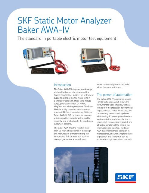
<strong>SKF</strong> Static Motor Analyzer<strong>Baker</strong> <strong>AWA</strong>-<strong>IV</strong>The standard in portable electric motor test equipmentIntroductionThe <strong>Baker</strong> <strong>AWA</strong>-<strong>IV</strong> integrates a wide rangeelectrical tests on motors that meet thehighest standards of quality. This instrumentsupports all major electric motor tests ina single portable unit. These tests includesurge, polarization index, DC HiPot,MegOhm and winding resistance. The <strong>Baker</strong><strong>AWA</strong>-<strong>IV</strong> is fully <strong>com</strong>pliant with industrystandardIEEE re<strong>com</strong>mendations. With the<strong>Baker</strong> <strong>AWA</strong>-<strong>IV</strong>, <strong>SKF</strong> continues to innovatewith its steadfast <strong>com</strong>mitment to quality,reliability, and products with the capabilitiescustomers demand.The <strong>Baker</strong> <strong>AWA</strong>-<strong>IV</strong> is the result of morethan 45 years of experience in the designand manufacture of motor winding testinstruments. This analyzer can performuser-programmable automatic testsas well as manually-controlled testswithin the same instrument.The power of automationThe <strong>Baker</strong> <strong>AWA</strong>-<strong>IV</strong> is designed aroundPC104 technology, which allows theinstrument to work efficiently withoutfans to cool the processor. It performs allrequested tests, stores the results, andcontinuously monitors voltage levelswhile testing. If the <strong>com</strong>puter detects aweakness in the insulation, the test isinterrupted, the operator is alerted, andall test parameters at the time of theinterruption are reported. The <strong>Baker</strong><strong>AWA</strong>-<strong>IV</strong> performs these operation inmicroseconds, and with a higher degreeof precision and safety than can beachieved through manual test methods.
Automatic or manual optionsThe <strong>Baker</strong> <strong>AWA</strong>-<strong>IV</strong> provides the option of performing automaticor manual tests. In manual mode, the system allows operatorcontrol over tests, voltage levels and data collection.Programmed operationThe <strong>Baker</strong> <strong>AWA</strong>-<strong>IV</strong> is the only high-voltage tester that can beuser-programmed with specific sets of tests to be implementedin the field. Pre-build work orders define which motors totest, the order of execution, and parameters for each test,including voltages, duration and pass-fail limits. Operatorscan then conduct tests in the field simply by connecting to theprogrammed motor to ensure a greater degree of reliabilityin testing procedures. This allows for repeatable maintenancetesting, which is vital to a successful PM program.Advanced data collectionWhen testing is <strong>com</strong>plete, results can be saved with the permanenttest record of each motor Such documentation is critical to any successfulreliability program. With the <strong>Baker</strong> <strong>AWA</strong>-<strong>IV</strong>, testing resultsare collected, stored, recalled and managed using standard MS Accessrelational database format. Reports can be generated fortrending, insurance records, or warranty requirements for customersthrough the <strong>Baker</strong> <strong>AWA</strong>-<strong>IV</strong> software or MS Word file formats.Report formats include RTF, MHTML and Microsoft Word. Thesedatabase files make it easy to transfer data to maintenance managementsoftware or other database tools and Access is ODBC<strong>com</strong>pliant.2
<strong>Baker</strong> <strong>AWA</strong>-<strong>IV</strong> FeaturesTurn-to-turn testingThe <strong>Baker</strong> <strong>AWA</strong>-<strong>IV</strong> incorporates the most advanced interturntest capabilities offered in a field-portable electric motoranalyzer. Computer control and waveform monitoring offermajor advantages over instruments confined to manual control.As with the DC step voltage test, the <strong>Baker</strong> <strong>AWA</strong>-<strong>IV</strong> startssurge generation at a low voltage. Each pulse applied to themotor’s winding is digitized, and the resultant waveform is<strong>com</strong>pared to previous waveforms to detect any sign of turn-toturnweakness. The pulse-to-pulse error area ration (PP-EAR)technique is applied to <strong>com</strong>pare waveform differences, and issensitive to less than one percent variance between coils.Shorts among windings in parallel can be located; such shortscould not be detected with visual <strong>com</strong>parisons of waveforms.With the <strong>Baker</strong> <strong>AWA</strong>-<strong>IV</strong>, fewer pulses are applied to a winding,which reduces the power required to perform a surge test. Witheach and every pulse, a new reference waveform is created astest voltages increase up to the determined maximum voltagelevel. If no turn-to-turn weaknesses are detected, the finalpulse waveform is stored digitally as the reference waveformfor future testing. This same waveform should serve as thereference for several years.• <strong>AWA</strong><strong>IV</strong>-12HO– High Output Unit for heavy duty testing (lowturn-count windings). Call for more specifics.• Universal power supply: 85 V AC-265 V AC• Surge test (all units) IEEE522 <strong>com</strong>pliant• MΩ, DA, PI, Stepped DC, and DC HiPot tests to 12 kV for<strong>AWA</strong><strong>IV</strong>-12, 6 kV for <strong>AWA</strong><strong>IV</strong>-6, 4 kV for <strong>AWA</strong><strong>IV</strong>-4, and 2 kVfor <strong>AWA</strong><strong>IV</strong>-2, with four ranges of measurement100/10/1/0.1 µA, 1,000/100/10/1 µA overcurrent trip levels.Accurate to 50,000 MΩ. DC power supply is regulated to0.01%. (IEEE <strong>com</strong>pliant)• Kelvin resistance bridge-relay matrix, with 9 A (<strong>AWA</strong> <strong>IV</strong>-12and <strong>AWA</strong><strong>IV</strong>-6), 5 A (<strong>AWA</strong><strong>IV</strong>-4 and <strong>AWA</strong><strong>IV</strong>-2) maximum appliedDC current source. Kelvin relay-matrix is <strong>com</strong>prised ofa separate, removable set of (3-<strong>AWA</strong><strong>IV</strong>, 2-<strong>AWA</strong>2.2) kelvinclips. Unit high voltage leads retain the ability to performtest sequence; however, for low resistances, the Kelvin testleads are used (IEEE <strong>com</strong>pliant)• MS Windows embedded operating system withPentium-class microprocessor equivalent <strong>com</strong>puterhardware• If loaded on a desktop <strong>com</strong>puter the <strong>AWA</strong> software generatesMS Word Reports.• Removable keyboard and mouse (not required for testing).• ELO touch screen for ease of operation during field testing.• USB for data transfer• RJ45 ethernet access plug for Cat5 ethernet connection.• <strong>AWA</strong> <strong>IV</strong>-6, <strong>AWA</strong><strong>IV</strong>-12, <strong>AWA</strong><strong>IV</strong>-12HO operate with all optional<strong>Baker</strong> power pack units• Shock mounted internal chassis, with Hard Drive shockmounting• PC104 system board with 100 percent optically isolatedsignal/readout and controls for high voltage circuitry• High-resolution color LCD with high color display capacity.• Improved testing capabilities:–– Continuous ramped HiPot (IEEE 95)–– Programmable Stepped HiPot (IEEE 95)–– Enhanced reference Surge waveform–– Improved PI/DA test (IEEE 43)–– Improved DC HiPot (IEEE 95)–– Improved Resistance test (IEEE 118)–– More sensitive Surge test (IEEE 522)3
<strong>Baker</strong> <strong>AWA</strong>-<strong>IV</strong>/12 <strong>Baker</strong> <strong>AWA</strong>-<strong>IV</strong>/12HO <strong>Baker</strong> <strong>AWA</strong>-<strong>IV</strong>/6 <strong>Baker</strong> <strong>AWA</strong>-<strong>IV</strong>/4 <strong>Baker</strong> <strong>AWA</strong>-<strong>IV</strong>/2Surge testOutput voltage 0 to 12,000 V 0 to 12,000 V 0 to 6,000 V 0 to 4,250 V 0 to 2,160 VMax output current 600 A 800 A 250 A 450 A 250 APulse energy 2.88 J 7.2 J 0.72 J 0.9 J 0.2 JStorage capacitance 0.04 µF 0.1 µF 0.04 µF 0.1 µF 0.1 µFSweep range 2.5 to 200 µs/Div 2.5 to 200 µs/Div 2.5 to 200 µs/Div 2.5 to 200 µs/Div 2.5 to 200 µs/DivVolts division 500/1,000/2,000/3,000 500/1,000/2,000/3,000 500/1,000/2,000/3,000 500/1,000/2,000/3,000 500/1,000/2,000/3,000Repetition rate 5 Hz 5 Hz 5 Hz 5 Hz 5 HzVoltage measurementand accuracy ± 12% ± 12% ± 12% ± 12% ± 12%DC HiPot testOutput voltage 0 to 12,000 V 0 to 12,000 V 0 to 6,000 V 0 to 4,250 V 0 to 2,160 VMax output current 1,000 µA 1,000 µA 1,000 µA 1,000 µA 1,000 µACurrent resolution 0.1, 1, 10, 100 µA/Div 0.1, 1, 10, 100 µA/Div 0.1, 1, 10, 100 µA/Div 0.1, 1, 10, 100 µA/Div 0.1, 1, 10, 100 µA/DivOver-currenttrip settings 1, 10, 100, 1.000 µA 1, 10, 100, 1.000 µA 1, 10, 100, 1.000 µA 1, 10, 100, 1.000 µA 1, 10, 100, 1.000 µAFull scale voltage andcurrent measurementand accuracy ± 5% ± 5% ± 5% ± 5% ± 5%MΩ accuracy ± 10% ± 10% ± 10% ±10% ± 10%Max MΩ reading 50,000 MΩ 50,000 MΩ 50,000 MΩ 50,000 MΩ 50,000 MΩResistancemeasurements 0.001 to 800 Ω 0.001 to 800 Ω 0.001 to 800 Ω 0.001 to 100 Ω 0.001 to 100 ΩPhysicalcharacteristicsWeight 42 lb 50 lb 42 lb 18 lb 18 lbDimensions,in (W x H x D) 16 x 8 x 21 16 x 8 x 21 16 x 8 x 21 15 x 8 x 8 15 x 8 x 8Power requirements85 to 264 V AC50/60 Hz at 2.5 A85 to 264 V AC50/60 Hz at 2.5 A85 to 264 V AC50/60 Hz at 2.5 A85 to 264 V AC50/60 Hz at 2.5 A85 to 264 V AC50/60 Hz at 2.5 ASealsMechatronicsBearingsand unitsServicesLubricationsystemsThe Power of Knowledge EngineeringDrawing on five areas of <strong>com</strong>petence and application-specific expertise amassed over 100 years,<strong>SKF</strong> brings innovative solutions to OEMs and production facilities in every major industry worldwide.These five <strong>com</strong>petence areas include bearings and units, seals, lubrication systems, mechatronics (<strong>com</strong>biningmechanics and electro nics into intelligent systems), and a wide range of services, from 3-D <strong>com</strong>putermodelling to advanced condition monitoring and reliability and asset management systems. A globalpresence provides <strong>SKF</strong> customers uniform quality standards and universal product availability.For additional information on <strong>SKF</strong> Condition Monitoring products, contact:<strong>Baker</strong> Instrument Company, an <strong>SKF</strong> Group Company4812 McMurry Avenue • Fort Collins, Colorado 80525 USATelephone: +1 970-282-1200 • FAX: +1 970-282-1010www.bakerinst.<strong>com</strong>www.skf.<strong>com</strong>® <strong>SKF</strong> is a registered trademark of the <strong>SKF</strong> GroupAll other trademarks are the property of their respective owners.© <strong>SKF</strong> Group 2012The contents of this publication are the copyright of the publisher and may not be reproduced (even extracts) unless prior writtenpermission is granted. Every care has been taken to ensure the accuracy of the information contained in this publication but no liabilitycan be accepted for any loss or damage whether direct, indirect or consequential arising out of the use of the information containedherein. <strong>SKF</strong> reserves the right to alter any part of this publication without prior notice.<strong>SKF</strong> Patents include: #US04768380 • #US05679900 • #US05845230 • #US05854553 • #US05992237 • #US06006164 •#US06199422 • #US06202491 • #US06275781 • #US06489884 • #US06513386 • #US06633822 • #US6,789,025 •#US6,792,360 • US 5,633,811 • US 5,870,699 • #WO_03_048714A1Publication 6753 EN – June 2012 • Printed on environmentally friendly paper.