Performance Evaluation of CoolMOS and SiC Diode for PFC ... - CPES
Performance Evaluation of CoolMOS and SiC Diode for PFC ... - CPES
Performance Evaluation of CoolMOS and SiC Diode for PFC ... - CPES

You also want an ePaper? Increase the reach of your titles
YUMPU automatically turns print PDFs into web optimized ePapers that Google loves.
<strong>Per<strong>for</strong>mance</strong> <strong>Evaluation</strong> <strong>of</strong> <strong>CoolMOS</strong> TM <strong>and</strong> <strong>SiC</strong> <strong>Diode</strong> <strong>for</strong> <strong>PFC</strong> ApplicationsWei Dong, Bing Lu, Qun Zhao <strong>and</strong> Fred C. LeeCenter <strong>for</strong> Power Electronics SystemsThe Bradley Department <strong>of</strong> Electrical <strong>and</strong> Computer EngineeringVirginia Polytechnic Institute <strong>and</strong> State UniversityBlacksburg, VA 24061, U. S. AAbstract—<strong>SiC</strong> diode exhibits almost zero reverse recoverycharge <strong>and</strong> <strong>CoolMOS</strong> TM achieves smaller R dson <strong>and</strong> fastswitching speed. These features make <strong>CoolMOS</strong> TM <strong>and</strong> <strong>SiC</strong>diode attractive <strong>for</strong> the single-phase <strong>PFC</strong> AC/DC front-endconverters. This paper examines the switching characteristics <strong>of</strong><strong>CoolMOS</strong> TM <strong>and</strong> <strong>SiC</strong> diode in comparison with the conventionalSi devices. Based on that, one single-phase <strong>PFC</strong> CCM boostconverter <strong>for</strong> distributed power system applications is built toevaluate the converter per<strong>for</strong>mance <strong>of</strong> using <strong>CoolMOS</strong> TM <strong>and</strong><strong>SiC</strong> diode. The experimental measurement results <strong>of</strong> theefficiency <strong>and</strong> the electromagnetic interference noise levelindicate the substantial per<strong>for</strong>mance improvement with use <strong>of</strong><strong>CoolMOS</strong> TM <strong>and</strong> <strong>SiC</strong> diode.I. INTRODUCTIONIn the history <strong>of</strong> the power electronics technology, the newdevices <strong>and</strong> the new topologies are always the pushing power<strong>of</strong> the development. The thyristor shows the beginning <strong>of</strong> thepower electronics. When the gate turn <strong>of</strong>f devices such asBJT <strong>and</strong> GTO come into existence, the power electronicstechnology got rapid development. The isolated gate devicessuch as MOSFET <strong>and</strong> IGBT make the power electronicsdevices easy to control <strong>and</strong> even much higher frequency. Inthe same time, people never stop the work to find a bettertopology to make use <strong>of</strong> the maximum capability <strong>of</strong> thedevices.For the AC/DC stage <strong>of</strong> the front-end distributed powersystem (DPS) applications, a single switch continuouscurrent-mode(CCM) boost <strong>PFC</strong> circuit is an attractivechoice, in which a fast MOSFET <strong>and</strong> a fast recovery Si diodeare used [1]. Although with the fast switching devices, thediode reverse-recovery related turn-on loss <strong>and</strong> the turn-<strong>of</strong>floss in the switch are still high, which mainly leads to lowefficiency at the low line <strong>for</strong> a <strong>PFC</strong> rectifier designed <strong>for</strong> thewide input voltage range (90V-260V). There<strong>for</strong>e, with theuse <strong>of</strong> the conventional devices, there have been a goodnumber <strong>of</strong> investigations on the snubber scheme <strong>for</strong> thesingle switch boost <strong>PFC</strong>. While most schemes complicate ineither auxiliary power stage or additional control scheme,some passive snubber techniques have been demonstrated tobe cost-effective in reducing the switching losses. Along withthe ef<strong>for</strong>ts <strong>of</strong> exploring circuit topologies, the devicetechnology is also continuously improved. New devices*This work made use <strong>of</strong> ERC Shared Facilities supported by the NationalScience Foundation under Award Number EEC-9731677.P + N -SN -N + subDGSN - P + N -N - epiN + subD(a)(b)Fig. 1. Structure <strong>of</strong> MOSFET: (a) conventional (b) <strong>CoolMOS</strong> TM .such as <strong>CoolMOS</strong> TM <strong>and</strong> the <strong>SiC</strong> diode have come intocommercial production recently, although the cost is high.<strong>CoolMOS</strong> TM is a new revolutionary technology <strong>for</strong> highvoltage power MOSFETs [2]. As shown in Fig. 1,<strong>CoolMOS</strong> TM implements a compensation structure in thevertical drift region <strong>of</strong> a MOSFET in order to improve the onstate resistance. Such a structure makes it possible to reducethe on-state resistance R dson <strong>of</strong> a 600V MOSFET by a factor<strong>of</strong> 5 <strong>for</strong> the same chip area. It literally changes the conception<strong>for</strong> the R dson limitations <strong>of</strong> the conventional MOSFETtechnologies, which was R dson ∝V 2.5 ds . In the mean time,<strong>CoolMOS</strong> TM technology can largely reduce the junctioncapacitance, as compared with the normal MOSFETtechnology. It is claimed the <strong>CoolMOS</strong> TM achieves the fastestswitching given the same chip size.<strong>SiC</strong> is a wide b<strong>and</strong>gap semiconductor material, <strong>and</strong> thus<strong>SiC</strong> Schottky can have a very low on-resistance with highrated voltage. From theory, the <strong>SiC</strong> Schottky diode can havea voltage rating more than 1000V <strong>and</strong> at present acommercial <strong>SiC</strong> Schottky diode has a maximum voltagerating <strong>of</strong> 600V, much higher than the Si Schottky diode.Another nice feature <strong>of</strong> <strong>SiC</strong> diode is almost no reverserecoverycharge. There<strong>for</strong>e, the turn-on loss <strong>of</strong> the switch isexpected to be substantially reduced.In recent years, some evaluation results <strong>of</strong> <strong>SiC</strong> diodesshowed signs <strong>of</strong> the improving switching loss <strong>of</strong> powerdevices but lower efficiency <strong>of</strong> the whole converter [3]. Thereason was that, a couple <strong>of</strong> years ago <strong>SiC</strong> diode exhibitedmuch higher conduction loss than Si diode. One most recentwork presents the overall efficiency results using<strong>CoolMOS</strong> TM <strong>and</strong> <strong>SiC</strong> diode in the <strong>PFC</strong> boost converter [4].However, the loss reduction mechanism was not clearlyPGPN -
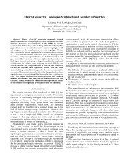
explained <strong>and</strong> the evaluation did not fully target the DPS <strong>PFC</strong>front-end applications. In addition, the EMI noiseper<strong>for</strong>mance was not addressed.In this paper, the switching characteristics <strong>of</strong> <strong>CoolMOS</strong> TM<strong>and</strong> <strong>SiC</strong> diode are obtained via the experiment. The deviceimpacts on a <strong>PFC</strong> boost converter <strong>for</strong> DPS applications areable to be distinguished through the measurements based ondifferent combinations <strong>of</strong> devices. Moreover, the EMIper<strong>for</strong>mance using <strong>SiC</strong> diode is presented.II. SWITCHING CHARACTERISTICS EVALUATIONTo evaluate the <strong>CoolMOS</strong> TM <strong>and</strong> the <strong>SiC</strong> Schottky diode, aswitching test bed is built to test the switching wave<strong>for</strong>mscompare with the normal MOSFET <strong>and</strong> Si diode. Theschematic <strong>of</strong> the switching test-bed is shown in Fig. 2.Applying the laminated power bus plane, as shown in Fig. 3minimizes the parasitic inductance <strong>of</strong> the current loopcomprised <strong>of</strong> the bus capacitor, the diode <strong>and</strong> the MOSFET.SDP06S60, which are from Infineon Inc. We tested fourcombinations <strong>of</strong> these devices, as explained in Table I.Table I. Device combinations used in switching test.Com. I Com. II Com. III Com. IV<strong>Diode</strong> RHRP860 SDP06S60 RHRP860 SDP06S60MOSFET IRFP460 IRFP460 SPW20N60S5 SPW20N60S5CurrentLossLossVoltageVoltageTurn <strong>of</strong>fTurn onCombination I: Normal MOSFET + Fast Si diodeLossLossCurrentµ0.1µ300mHCurrentVoltageVoltageCurrent2Ω*8Turn <strong>of</strong>fTurn onCombination II: Normal MOSFET + <strong>SiC</strong> diodeFig. 2. Switching test-bed schematicLossLossCurrent sensing resistorsCurrentVoltageVoltageCurrent<strong>Diode</strong>Turn <strong>of</strong>fTurn onCombination III: <strong>CoolMOS</strong> TM + Fast Si diodeMOSFETLossLossFig. 3. Test-bed setup.From this test-bed, we can not only obtain the switchingwave<strong>for</strong>ms to underst<strong>and</strong> the switching features <strong>of</strong> thedifferent devices but also get the switching loss caused by thevoltage <strong>and</strong> current overlap, which is very useful <strong>for</strong> the totalconverter loss breakdown.To compare with the <strong>CoolMOS</strong> TM <strong>and</strong> <strong>SiC</strong> Schottky diode,we choose the widely used devices such as the MOSFTIRFP460 <strong>and</strong> the fast recovery diode RHRP860. The<strong>CoolMOS</strong> TM is SPW20N60S5 <strong>and</strong> the <strong>SiC</strong> Schottky diode isCurrentVoltageVoltageTurn <strong>of</strong>fTurn onCombination IV: <strong>CoolMOS</strong> TM + <strong>SiC</strong> diodeCurrentFig. 4. Compare switching wave<strong>for</strong>ms <strong>for</strong> different devices.Voltage: 200V/div; current: 20 A/div; loss: 400µJ/div; time: 20nS/div.The switching wave<strong>for</strong>ms are shown in Fig. 4 <strong>and</strong> the gateresistor is 9.1Ω <strong>for</strong> all the combinations. Comparing theswitching wave<strong>for</strong>ms <strong>of</strong> combination I <strong>and</strong> combination II, itis easy to see the effect caused by the <strong>SiC</strong> diode. The turn <strong>of</strong>f
wave<strong>for</strong>ms are almost identical because the turn <strong>of</strong>f processis largely depended on the MOSFET’s characteristics otherthan diode. At turn-on, the <strong>SiC</strong> diode exhibits minimal thereverse recovery current at the di/dt <strong>of</strong> 1100 A/µS while theSi diode shows about 16 A <strong>of</strong> the reverse recovery current. Sothe turn on loss is largely reduced by <strong>SiC</strong> diode, as confirmedin the wave<strong>for</strong>ms <strong>of</strong> combination I <strong>and</strong> II <strong>of</strong> Fig. 4.From combination I to III, the switch is changed from anormal MOSFET into a <strong>CoolMOS</strong> TM . It can be easily seenthat the <strong>CoolMOS</strong> TM has a much faster turn <strong>of</strong>f speed ascompared with the normal MOSFET. The <strong>CoolMOS</strong> TM takesjust half <strong>of</strong> the turn <strong>of</strong>f time that the normal MOSFET need,which can help reduce the turn <strong>of</strong>f loss <strong>of</strong> the MOSFET.Specially, the <strong>CoolMOS</strong> TM has the voltage rating <strong>of</strong> 600Vwhile the conventional MOSFET in the same package canonly block 500V. There<strong>for</strong>e, at turn-<strong>of</strong>f the <strong>CoolMOS</strong> TM canbe driven mush faster than the normal MOSFET. On theother h<strong>and</strong>, the current rising slope when <strong>CoolMOS</strong> TM turnson is slower than the normal MOSFET. It is difficult tounderst<strong>and</strong> this phenomenon if assuming all the MOSFETjunction capacitance has the same feature <strong>for</strong> both turn-<strong>of</strong>f<strong>and</strong> turn-on. There<strong>for</strong>e, more device structure levelunderst<strong>and</strong>ing is required to explain the phenomenon. Fromthe application point <strong>of</strong> view, it is also desired to have a fastturn-on speed <strong>for</strong> <strong>CoolMOS</strong> TM .When using the <strong>CoolMOS</strong> TM <strong>and</strong> <strong>SiC</strong> diode together, theswitching feature is quite underst<strong>and</strong>able based on thepreceding analysis <strong>of</strong> the individual device’ impact. Asshown in combination IV <strong>of</strong> Fig. 4, both the <strong>CoolMOS</strong> TM <strong>and</strong>the <strong>SiC</strong> diode affect the turn-on wave<strong>for</strong>ms. The <strong>CoolMOS</strong> TMcauses a slower current rising while the <strong>SiC</strong> diode nearlyeliminates the diode reverse recovery current. For the turn<strong>of</strong>f,the <strong>CoolMOS</strong> TM leads to fast switching while the <strong>SiC</strong>diode has no effect on the switching loss.When <strong>SiC</strong> diode is used, the adequate gate driving <strong>for</strong>switch can make turn-on speed fast <strong>and</strong> will not cause morereverse recovery charge. In addition, the <strong>CoolMOS</strong> TM can bedriven much faster at turn-<strong>of</strong>f than the conventionalMOSFET without causing excessive voltage stress.There<strong>for</strong>e, it is expected the switching losses at turn-on <strong>and</strong>turn-<strong>of</strong>f are greatly reduced with use <strong>of</strong> the <strong>CoolMOS</strong> TM <strong>and</strong><strong>SiC</strong> diode.Figure 5 summarizes the measured turn-on loss <strong>for</strong>different combinations <strong>of</strong> devices. All the turn on losses arebased on the 9.1Ω gate resistor. Since the <strong>CoolMOS</strong> TM has aslower current rising rate, it causes larger turn on losscompare with the normal MOSFET. But we can drive the<strong>CoolMOS</strong> TM faster to reduce the turn on loss. In figure 5, theturn on loss <strong>of</strong> <strong>CoolMOS</strong> TM <strong>and</strong> <strong>SiC</strong> Schottky diodecombination using 0Ω gate resistor is shown. It can be easilyseen that the turn on loss is reduced by increasing the drivingspeed. So the turn on loss by using <strong>CoolMOS</strong> TM can besimilar to the normal MOSFET turn on loss. The comparison<strong>of</strong> turn-<strong>of</strong>f loss energy is shown in Fig. 6. Regardless theswitching current level, the turn-<strong>of</strong>f loss can be reduced bythe <strong>CoolMOS</strong> TM . In the same time, the normal MOSFETcan’t be driven so fast since its voltage rating is only 500V,which means it doesn’t have a large margin <strong>for</strong> the voltageovershoot caused by the parasitic inductor. For the<strong>CoolMOS</strong> TM , since it has a voltage rating <strong>of</strong> 600V, whichmeans a much larger margin compare with the normalMOSFET,itcanbedrivenmuchfastertoreduceturn<strong>of</strong>flossmore. From this point <strong>of</strong> view, <strong>CoolMOS</strong> TM can largelyreduce the turn <strong>of</strong>f loss. In figure 6, the turn <strong>of</strong>f energy loss <strong>of</strong><strong>CoolMOS</strong> TM <strong>and</strong> <strong>SiC</strong> Schottky diode combination by using 0gate resistor is shown, it can be seeing that by driving faster<strong>of</strong> the <strong>CoolMOS</strong> TM , a much lower turn <strong>of</strong>f loss can beachieved.From the switching loss summary, it can conclude that witha suitable fast gate driving, the <strong>CoolMOS</strong> TM <strong>and</strong> <strong>SiC</strong> diodeare expected to lead to considerable switching loss reduction.6005004003002001000300250200150100500uJ<strong>CoolMOS</strong>&860460&860<strong>CoolMOS</strong>&<strong>SiC</strong><strong>CoolMOS</strong>&<strong>SiC</strong>@0R5 10 15 20 25 AuJFig. 5. Turn on energy loss.460&860460&<strong>SiC</strong><strong>CoolMOS</strong>&860<strong>CoolMOS</strong>&<strong>SiC</strong><strong>CoolMOS</strong>&<strong>SiC</strong>@0Rg5 10 15 20 25AFig. 6. Turn <strong>of</strong>f energy loss.Fig. 7. Single switch boost <strong>PFC</strong> circuit.Load
III. CONVERTER LEVEL EVALUATIONTo evaluate the per<strong>for</strong>mance <strong>of</strong> <strong>CoolMOS</strong> TM <strong>and</strong> <strong>SiC</strong>Schottky diode <strong>for</strong> DPS applications, a 1kW single switchCCM <strong>PFC</strong> circuit is built, as shown in Fig. 7. No any snubbercircuit is implemented during the test. Two MOSFETs areparalleled to ensure the enough thermal h<strong>and</strong>ling capability at90 Vac <strong>of</strong> low line input. The switching frequency is selectedto be about 100 kHz <strong>and</strong> the output voltage is regulated at390 Vdc.The efficiency comparison <strong>of</strong> different combinations <strong>of</strong> thedevices is shown in Fig. 8. It is clear that the <strong>CoolMOS</strong> TM<strong>and</strong> the <strong>SiC</strong> diode can achieve more than 4% efficiencyincrease, as compared with the conventional devices. Fromthe switching loss evaluation, it is known that the turn-on lossis about twice <strong>of</strong> the turn-<strong>of</strong>f loss <strong>for</strong> a pair <strong>of</strong> theconventional MOSFET <strong>and</strong> Si diode. However, the <strong>SiC</strong> diodealone in the <strong>PFC</strong> circuit achieves less efficiency increasecompared with the combination <strong>of</strong> <strong>CoolMOS</strong> TM <strong>and</strong> Si diode.As we know, the <strong>CoolMOS</strong> TM also achieves smaller Rdsonthan the normal MOSFET. There<strong>for</strong>e, it is reasonable <strong>for</strong> the<strong>CoolMOS</strong> TM to realize better efficiency per<strong>for</strong>mance than <strong>SiC</strong>diode. When use the <strong>CoolMOS</strong> TM with the Si diode, theswitch’s case temperature reach 70 o C at 100Vac <strong>of</strong> inputvoltage <strong>and</strong> the converter almost enters the thermal run-away.There is no possibility <strong>for</strong> the converter to deliver 1kW at90Vac <strong>of</strong> input. In comparison with the incapability <strong>of</strong> thedelivering 1kW power when using either <strong>CoolMOS</strong> TM or <strong>SiC</strong>diode, the combination <strong>of</strong> the <strong>CoolMOS</strong> TM or the <strong>SiC</strong> diode<strong>of</strong>fers the high efficiency at 90Vac <strong>of</strong> input. The switch’scase temperature is only 47 o C.Efficiency [%]99989796959493929190IRF460+RHRP860<strong>CoolMOS</strong>+RHRP860IRF460+<strong>SiC</strong> diode<strong>CoolMOS</strong>+<strong>SiC</strong> diode90 110 130 150 170 190Input Voltage [V ac ]Fig. 8. Efficiency comparison <strong>of</strong> 1kW <strong>PFC</strong> circuit using different devices.Since the <strong>SiC</strong> diode has no reverse recovery current duringswitch’s turn-on, the voltage ringing across the diode, which<strong>of</strong>ten occurs due to snap feature <strong>of</strong> the conventional diode, isexpected to be small. It is interesting to evaluate the EMIper<strong>for</strong>mance brought by the <strong>SiC</strong> <strong>and</strong> the <strong>CoolMOS</strong> TM .Sincethe conventional device-based <strong>PFC</strong> converter can onlyoperate at the input no less than 120Vac, the EMI test isconducted at 120Vac <strong>of</strong> input. Figure 9 gives the conductedDB(µV)120110100RHRP86090807060<strong>SiC</strong> <strong>Diode</strong>5040100 k 1M 10 M 100 MFig. 9. Total EMI noise <strong>of</strong> the converter using RHRP860 <strong>and</strong> <strong>SiC</strong> diode.EMI noise comparison between the Si diode <strong>and</strong> the <strong>SiC</strong>diode case on the 1kW CCM <strong>PFC</strong> converter. As seen fromFig. 9, the <strong>SiC</strong> diode-based converter shows the less EMInoise around 20~30 MHz. The EMI spectra in the rest <strong>of</strong>frequency region are essentially similar <strong>for</strong> both <strong>SiC</strong> <strong>and</strong> Sidiode cases. Further decomposition <strong>of</strong> EMI noisemeasurement shows that mainly the common mode noise at20~30 MHz is reduced with the use <strong>of</strong> <strong>SiC</strong> diode.IV. CONCLUSIONSIn this paper, the <strong>CoolMOS</strong> TM <strong>and</strong> <strong>SiC</strong> Schottky diodewere tested at the device level <strong>and</strong> the converter level. Theexperimental results show that the <strong>CoolMOS</strong> TM <strong>and</strong> the <strong>SiC</strong>diode can largely increase the efficiency <strong>of</strong> the front-end <strong>PFC</strong><strong>for</strong> DPS applications <strong>for</strong> wide range <strong>of</strong> input voltage. TheEMI per<strong>for</strong>mance using <strong>SiC</strong> diode is verified to be no worsethan that using Si diode. There<strong>for</strong>e, the evaluation resultssuggest the great possibility <strong>of</strong> applying <strong>CoolMOS</strong> TM <strong>and</strong> <strong>SiC</strong>diode in the front-end <strong>PFC</strong> converter.V. ACKNOWLEDGEMENTThe authors are grateful to Infineon Inc <strong>for</strong> providing the<strong>CoolMOS</strong> TM <strong>and</strong> <strong>SiC</strong> diodes. The authors would also like tothank Mr. Huijie Yu <strong>and</strong> Mr. Xudong Huang <strong>for</strong> their helpfuldiscussions on the switching test circuit implementation.REFERENCES[1] M. S. Elmore, “Input current ripple cancellation in synchronized,parallel connected critically continuous boost converters,” in IEEEAPEC Conf. Rec., 1996, pp. 152-158.[2] L. Lorenz, M . Marz, A. Knapp <strong>and</strong> M. Marz, “ <strong>CoolMOS</strong> TM -a newmilestone in high voltage power MOS,” in ISPSD Conf. Rec., 1998, pp.3-10.[3] A. Elasser, M. Kheraluwala, M. Ghezzo, R. Steigerwald, N.Krishnamurthy <strong>and</strong> J. Kretchmer " A comparative evaluation <strong>of</strong> newsilicon carbide diodes <strong>and</strong> state-<strong>of</strong>-art silicon diodes <strong>for</strong> powerelectronics applications," in IEEE IAS Conf. Rec., 1999, pp. 341-345.[4] L. Lorenz, G. Deboy <strong>and</strong> I. Zverev, "Matched pair <strong>of</strong> <strong>CoolMOS</strong> TMtransistor with <strong>SiC</strong>-Schottky diode-advantages in applications," inIEEE IAS Conf. Rec., 2000, pp. 376-383.