Victrix Zeus instructions - RVR.ie
Victrix Zeus instructions - RVR.ie
Victrix Zeus instructions - RVR.ie
You also want an ePaper? Increase the reach of your titles
YUMPU automatically turns print PDFs into web optimized ePapers that Google loves.
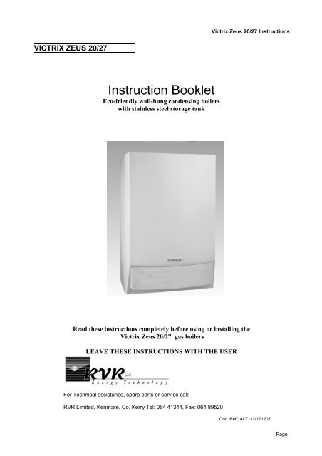
<strong>Victrix</strong> <strong>Zeus</strong> 20/27 InstructionsVICTRIX ZEUS 20/27Instruction BookletEco-fr<strong>ie</strong>ndly wall-hung condensing boilerswith stainless steel storage tankRead these <strong>instructions</strong> completely before using or installing the<strong>Victrix</strong> <strong>Zeus</strong> 20/27 gas boilersLEAVE THESE INSTRUCTIONS WITH THE USERFor Technical assistance, spare parts or service call:<strong>RVR</strong> Limited, Kenmare, Co. Kerry Tel: 064 41344, Fax: 064 89520Doc. Ref.: ALT112/171207Page
<strong>Victrix</strong> <strong>Zeus</strong> 20/27 InstructionsSeparated Flue SystemsSeparated 80/80 flue kitThis kit enables separation of the exhaust and air intakepipes as shown in the figure.Combustion products are expelled from pipe (A) (inplastic material resistant to acidic condensates). Air istaken in through pipe (B) (also in plastic material) forcombustion.Intake pipe (B) can be installed either on the right or lefthand side of the central exhaust pipe (B). Both pipescan be or<strong>ie</strong>nted in any direction.Assembly:Install the flange (4) on the central hole of the boiler insertingthe seal (1), positioning it with the round protrusionsdownwards in contact with the boiler flange andtighten using the screws suppl<strong>ie</strong>d with the kit.Remove the sealing plate from the air intake and replaceit with flange (3)inserting seal (2) which is alreadyfitted on the boiler and tighten using the screws suppl<strong>ie</strong>d.Insert bends (5) with the male end (smooth) in the femaleend of the flanges (3&4). Fit the male end of theintake terminal (6) up to the stop on the female end ofthe bend (5), making sure that the relevant internal andexternal sealing rings are fitted. Fit the male of the exhaustpipe up to the stop on the female end of the bend,making sure that the internal sealing ring is fitted; thiswill ensure a seal and joining of the elements making upthe kit.A lubricant may assist in overcoming the friction of the seals. Oils and conventional greases are not compatiblewith the EPDM seals used and should never be used for this purpose. Silicone sprays are compatiblewith EPDM and may be used. Please contact <strong>RVR</strong> for more information.A supporting clamp should be installed every three meters. The flue system should be slightly inclined sothat any condensate flows towards the boiler. This avoids any drips from the external flue terminal.The maximum possible overall length without any bends is 36 straight, horizontal meters or 41straight, vertical meters regardless of whether they are used in intake or exhaust. See the sectionon extended flue design for more information.Page 7
<strong>Victrix</strong> <strong>Zeus</strong> 20/27 InstructionsFlue calculations for more complex systemsEach component of the air inlet/flue system has a resistance factor . These are given in the following tables.The resistance factor var<strong>ie</strong>s depending on whether the component in question conveys fresh inlet air or hotcombustion gases. All boilers have a maximum resistance factor of 100. The sum of all components in theflue system must not exceed the maximum overall resistance factor of 100.Page 8
<strong>Victrix</strong> <strong>Zeus</strong> 20/27 InstructionsExample:Flue system consists of 9m of 80mm air intake pipe with 3 x 90˚ bends and 6m of exhaust pipe with 2 x 90˚bends.Component Resistances:Component Resistance Quantity Total80mm Intake pipe 0.87 9 7.8390˚ air intake bend 1.9 3 5.780mm Flue pipe 1.2 6 7.290˚ Flue bend 2.6 2 5.2Total Flue Resistance25.93In this case the total resistance of thesystem is less than 100. The flue designis acceptable.Page 9
<strong>Victrix</strong> <strong>Zeus</strong> 20/27 InstructionsTerminal PositionMin. DistanceA Directly below an opening, air brick, windows, etc.B Below gutters, soil pipes or drain pipesC Below eavesD Below balcon<strong>ie</strong>s or car port roofE From a vertical drain pipe of soil pipeF From an internal or external cornerG Above ground, roof or balcony levelH From a surface facing the terminalI From a terminal facing a terminalJ From an opening in the car port (door, window) into dwellingK Vertically from a terminal on the same wallL Horizontally from a terminal on the same wallM Horizontally from an opening, air brick, window etc.Below horizontally hinged windows where exhaust is directed upwardsBelow horizontally hinged windows where exhaust is not directed upwards300 mm75mm75mm75mm75mm75mm300mm600mm1200mm1200mm1500mm300mm300mm3000mm1000mmThe flue terminal must be exposed to the external air and the position must allow the free passage of airacross it at all times. In certain weather conditions the terminal may emit a plume of steam. Avoid positioningthe terminal where this may cause a nuisance. If the terminal is fitted within 850 mm of a plastic orpainted gutter or 450 mm of painted eaves or 300 mm of a plastic car port roof, an aluminium sh<strong>ie</strong>ld at least1 m long should be fitted to the underside of the gutter or painted surface. If the terminal is fitted less than 2m above a surface to which people have access, the terminal must be protected by a terminal guard.IMPORTANT— Failure to install flue systems correctly may lead to serious injury or death. Ensurethat:• Only flues specifically designed for condensing boilers and provided by <strong>RVR</strong> Energy TechnologyLimited are used.• The flue slopes slightly towards the boiler by between 1 and 2 degrees to ensure any condensateflows towards the boiler. Failure to do this will result in condensate dripping from the flue terminal.• The flue is adequately supported along it’s length so that it is straight and cannot be moved withoutusing a tool.• The flue system has no low points where condensate can collect.• All flue terminals are securely fixed.• No chemicals, detergents, solvents or liquids of any kind are used in the assembly of the flue system.Talc may be used as a lubricant where necessary.• All joints and connections are properly assembled to prevent leakage and all seals are properlyseated.• The flue is thoroughly tested for leaks after installation.Page 10
<strong>Victrix</strong> <strong>Zeus</strong> 20/27 InstructionsBoiler LocationThe boiler is not suitable for external installation.The boiler must be installed on a flat vertical wall which is capable of supporting the weight of the boiler.The boiler can be fitted to or adjacent to a wall comprising of a combustible material without the need for aspecial thermal insulation barr<strong>ie</strong>r.The boiler may be installed in any room or internal space, although particular attention is drawn to the requirementsof the current IEE Wiring Regulations. Where a room sealed boiler is installed in a room containinga bath or shower, it must not be possible for a person using the bath or shower to touch any electricalswitch or boiler control utilising mains electricity.The boiler may be installed in a cupboard or compartment, provided it is correctly designed for that purpose.NB: Adequate clearances are required to allow servicing of the boiler. Please see page 3.Page 11
<strong>Victrix</strong> <strong>Zeus</strong> 20/27 InstructionsCentral Heating SystemThe boiler is designed for use in a sealed central heating system. The system should be designed to operatewith flow temperatures of up to 80°C. When designing the system, the pump head, expansion vesselsize, mean radiator temperature, etc. must be taken into account.The pressure losses in the system must be compatible with the boiler circulation pump. See pump performancegraph below:Pump performance curvesFlow—Head Graph:The pump head depends on how the system bypass is adjusted.<strong>Victrix</strong> 20<strong>Victrix</strong> 27A. Head available at max pump speed with by-pass closed (adjustment screw fully screwed in)B. Head available at max pump speed (screw tightened 4 to 5 turns - bypass partially open)C. Head available at max pump speed with by-pass open (adjustment screw fully unscrewed)System volume - The 10 litre expansion vessel incorporated into the boiler is pre-charged to 1.0 bar and issuitable for a sealed heating system with a maximum water content of 100 litres. Above 100 litres, considerationshould be given to fitting an additional expansion vessel. To check correct operation of the expansionvessel(s) the system pressure should not be more than 2.5 bar when the system is at maximum operatingtemperature.The boiler is suppl<strong>ie</strong>d with the following components built in:-Central Heating Pressure rel<strong>ie</strong>f valve - complying with BS 6759 and set to operate at 3 bar. The dischargepipe must be routed clear of the boiler to a drain, so that it can be seen, but cannot cause injury to personsor property.A Pressure gauge is included to indicate the pressure of the central heating system.Page 12
The most important components of the system are shown in the diagram below.<strong>Victrix</strong> <strong>Zeus</strong> 20/27 Instructions• The cold water supply for the water heating side of the system may come from a booster pump or thecold water mains where this is permitted by the local authority.• A non-return valve must be installed on the cold feed to the boiler. This prevents expanding hot waterback-feeding into the cold side of the system.• The boiler includes an automatic bypass. It is not necessary to make any further provision for systembypasses.• The boiler condensate outlet must be connected to a drain. Metal pipes must not be used for thispurpose as the slightly acidic condensate will lead to rapid corrosion. Plastic must be used for thispurpose.Filling the central heating systemThe system design pressure (cold) should be set to 1.0 bar. This pressure is equivalent to a static head of10.2 metres of water. Provision should be made to replace water lost from the system. This can be bymanual or automatic means.Filling of the system must be carr<strong>ie</strong>d out in a manner approved by the local authority. Where allowed, thesystem may be filled via a temporary connection as shown below or by using the integrated filling valve inthe boiler. After filling, always disconnect the flexible hose of the filling loop if used and close the fillingvalve in the boiler.All fittings used in the system must be able to withstand pressures up to 3 bar. Drain taps (to BS 2879)must be used to allow the system to be completely drained. The heating system should be thoroughlyflushed before the boiler is connected and again after the first heating. If it is necessary to add inhibitor tothe central heating system, contact <strong>RVR</strong> Ltd. for guidance.Page 13
<strong>Victrix</strong> <strong>Zeus</strong> 20/27 InstructionsDomestic Hot Water SystemMains water pressurised unvented system are generally not permitted in Ireland. A cold water storage tankand a pressure boosting pump will normally provide a pressurised cold water supply. The pressurisationpump should provide a water pressure of between 1 and 3 bar. However, all taps and mixing valves usedwith the hot water system must be suitable for operating at a pressure of up to 5.5 bar. The use of fittingsdesigned for open, low pressure systems should be avoided as this will lead to excessive water flow rates.To ensure economic use, the pipe runs between the boiler and taps should be in 15 mm copper pipe and beas short as possible. Where possible the pipe work should be insulated to reduce heat loss.Before the cold water supply pipe is connected to the boiler, it should be thoroughly flushed out to avoid thedanger of dirt or foreign matter entering the boiler.The stored water temperature is adjustable to a maximum of 55°C. In hard water areas this should avoidpossible scale build-up. However, if descaling is necessary contact <strong>RVR</strong> Limited for guidance.Unvented Hot Water Storage SystemThe installation is subject to Building Regulations and the Water Bye Laws of the Local Authority.The <strong>Victrix</strong> <strong>Zeus</strong> 20/27 boiler is suppl<strong>ie</strong>d with all the components required for a safe and effic<strong>ie</strong>nt unventedhot water system. An air cushion which is present at the top of the 54l storage vessel provides some of theexpansion for the domestic hot water system. The balance is provided by the additional DHW expansionvessel installed within the boiler casing.NOTE: In the Dublin City Council area, the council requires that the minimum internal diameter ofpipes connected to the boiler DHW connections should not be less that 13mm. As 1/2” thermoplasticpipe does not provide the minimum diameter, the minimum suitable thermoplastic pipe size is3/4”Discharge pipe - The discharge pipes from the expansion rel<strong>ie</strong>f valves must be routed to a tundish in1/2” (or 15 mm )pipe. The discharge pipe work from both rel<strong>ie</strong>f valves may be joined together in the samesized pipe, providing at least 3/4” (or 22 mm) pipe work is connected downstream of the tundish.Tundish - The tundish must be positioned within 500 mm of the appliance, so that it is visible to the Userand away from electrical devices. The minimum size of the discharge pipe downstream of the tundish isgiven in the following table.15mm (1/2”)22mm (3/4”)28mm (1”)35mm (11/4”)Page 14
<strong>Victrix</strong> <strong>Zeus</strong> 20/27 InstructionsTundish installationThe discharge pipework from the tundish:-1. Shall fall continuously through its length.2. Shall be of a heat resistant material, e.g. metal.3. Shall not be fitted with any valves or taps.4. Shall discharge to a safe visible position, e.g. onto the surface of an external wall or into a gulley.5. Shall have a minimum of 300 mm straight pipework directly from the tundish.Note: Where children may play or otherwise come into contact with discharges, a wire cage or similarguard must be positioned to prevent contact whilst maintaining visibility.Please see the diagrams below for suggested methods of terminating the discharge pipe safely. Where asingle pipe serves a number of discharges, such as in blocks of flats, the number served should be limitedto not more than 6 systems so that any installation can be traced reasonably easily. The single commondischarge pipe should be at least one pipe size larger than the largest individual discharge pipe to be connected.If the system is installed where discharges from safety devices may not be apparent, i.e. in dwellingsoccup<strong>ie</strong>d by blind, infirm or disabled people, consideration should be given to the installation of anelectronically operated device to warn when discharge takes place.High Level TerminationAt high level, discharge onto a roof is acceptable providingthe roof is capable of withstanding high temperaturesand there is a distance of 3 m from anyplastic guttering systems that would collect such discharge.Example:-The example below is for a G½ temperature rel<strong>ie</strong>f valve with adischarge pipe (D2) having four elbows and a length of 7 m from thetundish to the point of discharge.From Table :-Maximum resistance allowed for a straight length of 22 mm copper discharge pipe (D2) from a G½ temperaturerel<strong>ie</strong>f valve is 9 m. Subtract the resistance for four 22 mm elbows of 0.8 m each = 3.2 m. Therefore themaximum permitted length equates to 9 - 3.2 = 5.8 m5.8 m is less than the actual length of 7 m therefore calculate the next largest size.Maximum resistance allowed for a straight length of 28 mm pipe (D2) from a G½ temperature rel<strong>ie</strong>f valveequates to 18 m.Subtract the resistance for four 28 mm elbows at 1.0 m each = 4 m.Therefore the maximum permitted length equates to 18 - 4 = 14 mAs the actual length is 7 m, a 28 mm (D2) copper pipe will be satisfactory.Page 15
<strong>Victrix</strong> <strong>Zeus</strong> 20/27 InstructionsOperation and Maintenance InstructionsAn annual maintenance of the boiler and heating system is recommended. This ensures that the optimalsafety, performance and operation characteristics of the boiler remain unchanged over time.WarningsNever expose the wall-mounted boiler to direct vapours from a cooking surface. Use of the boiler by unskilledpersons or children is strictly prohibited.Never touch the flue extraction terminal (if fitted) due to the risk of burning caused by high temperatures;For safety purposes, check that the concentric air intake/flue exhaust terminal (if fitted), is not blocked. Iftemporary shutdown of the boiler is required, proceed as follows:a) drain the heating system if anti-freeze is not used;b) shut off all electrical, water and gas suppl<strong>ie</strong>s.When building or renovation work is carr<strong>ie</strong>d out in the vicinity of the flue outlet, switch off the boiler and oncompletion of work ensure that a qualif<strong>ie</strong>d technician checks the safety of the installation. Never clean theappliance or connected parts with flammable substances. Never leave containers or flammable substancesin the same environment as the appliance.Electrical Safety- never touch the appliance with wet hands or other parts of the body and never touch when barefoot.- never pull electrical cables or leave the appliance exposed to atmospheric agents (rain, sunlight, etc.);- the appliance power supply cable must never be replaced by the user;- in the event of damage to the cable, switch off the appliance and contact a qualif<strong>ie</strong>d service technician.- in the event of prolonged periods when the boiler is not in use, turn off the main power switch.Using the BoilerBefore lighting, make sure that the system is full of water and that the manometer (9) indicates a pressureof 1 - 1.2 bar.-Open the gas valve on the gas supply to the boiler.-Turn main switch (5) to Hot Water or Hot Water/Heating.N.B.: With the switch set to the central Heating temperature setting is not active, and the domesticwater temperature is controlled by selector (3). With the switch set to the central heating temperatureis set using selector (2) while selector (3) is used for the domestic hot water. Turn the selectors clockwiseto raise the temperature, anticlockwise to lower it. Boiler operation is now automatic.Gaudium Magnum System - When the Gaudium Magnum switch (6) is in the position, the flow ratepossible for domestic hot water is increased when the storage temperature is more than 50°C. If the temperatureof the stored hot water drops below 41°C, the system is automatically disabled. Please see page14 for further information on operating the boiler.Antifreeze functions:The boiler is equipped with an anti-freeze system in both central heating and hot water modes:When the temperature measured in the central heating system falls below 4 C, the boiler is automaticallyfired until a boiler temperature of 35ºC is ach<strong>ie</strong>ved.When the temperature measured in the hot water tank falls below 4 C, the boiler is automatically fired untila boiler temperature of 8ºC is ach<strong>ie</strong>ved.Page 16
<strong>Victrix</strong> <strong>Zeus</strong> 20/27 InstructionsOperation and Maintenance InstructionsBoiler display and indicatorsDL1 - Green LED that comes on when the boiler is operating in heating or antifreeze mode.DL2 - Green LED that comes on when the boiler is working in domestic hot water mode.DL3 - Orange LED that comes on when the burner is operating.LCD Display unitDepending on conditions, the LCD display indicates:- The boiler supply temperature.- The value set during heating and DHW temperature adjustment (for a time of 5 seconds after setting thetemperature using the selector switch)- the wording EC (external controls) with the optional CAR remote control is used.- Fault conditions, the code number corresponding to the fault is displayed:01 = Lockout due to ignition failure02 = Lockout due to overheat thermostat triggering05 = breakage of heating NTC sensor (NR)10 = no-water safety device12 = NTC DHW sensor failure (storage tank)14 = incorrect ignition unit and board connection / faulty ignition unit16 = fan failure (faulty fan)17 = incorrect fan speed26 = no-water safety switch closed with pump not working31 = incompatible remote controlReset ButtonThe Reset button is used to reset certain faults. A reset will occur when the button is pressed.Page 17
<strong>Victrix</strong> <strong>Zeus</strong> 20/27 InstructionsAnnual maintenance proceduresThe following checks and maintenance should be performed at least once a year.- Clean the flue side of the heat exchanger.- Clean the main burner.- Make a visual inspection of the flue extraction hood for wear or corrosion.- Ensure correct ignition and operation.- Ensure correct settings of the burner in domestic water and heating modes.- Verify correct operation and adjustment of the boiler, in particular:- operation of the electrical main switch on the boiler;- operation of the system control thermostat;- operation of the domestic water control thermostat.- Ensure gas soundness of the gas intake circuit; insert a “U” or digital type pressure gauge in the pressuretest point upstream of the gas valve and then close the boiler shutoff valve. No pressure variation mustoccur in the next five minutes on the gauge.- Ensure activation of the device for protection against the ionisation flame control gas; activation time mustbe less than ten seconds- Visually inspect to check for leakage of water or oxidation of fittings.- Check visually that the water safety valve outlets are not blocked and that the tundish is clear.- Check that the charge of the expansion vessel after discharging system pressure to the zero setting(check via boiler pressure gauge), is at 1,0 bar.- Check that the system static pressure (in cold conditions and after system recharging via the filling valve )is between 1 and 1.2 bar.- Check visually that the safety and control devices have not been tampered with and/or shorted, in particular:- temperature safety thermostat;- air pressure switch.- Check the integrity of boiler Magnesium Anode.- Ensure correct maintenance and condition of the electrical installation with particular reference to:electrical cables must be correctly routedno traces of black marking or burnsPage 19
Variable Heat Output:<strong>Victrix</strong> <strong>Zeus</strong> 20/27 Instructions<strong>Victrix</strong> 20:N.B.: Pressure values specif<strong>ie</strong>d in the table indicate the difference of pressure values between the gasvalve outlet and the combustion chamber. Adjustments are carr<strong>ie</strong>d out using a differential pressuregauge.<strong>Victrix</strong> 27:Page 20
<strong>Victrix</strong> <strong>Zeus</strong> 20/27 Instructions<strong>Victrix</strong> <strong>Zeus</strong> 20/27 Wiring Diagram:Page 21


