Color-Tec Method - State Coalition for Remediation of Drycleaners
Color-Tec Method - State Coalition for Remediation of Drycleaners
Color-Tec Method - State Coalition for Remediation of Drycleaners
Create successful ePaper yourself
Turn your PDF publications into a flip-book with our unique Google optimized e-Paper software.
A Field-Based <strong>Method</strong> <strong>for</strong> Rapid Analysis <strong>of</strong><br />
Total Chlorinated Volatile Organic Halocarbons<br />
In Ex-Situ Soil and Water Samples<br />
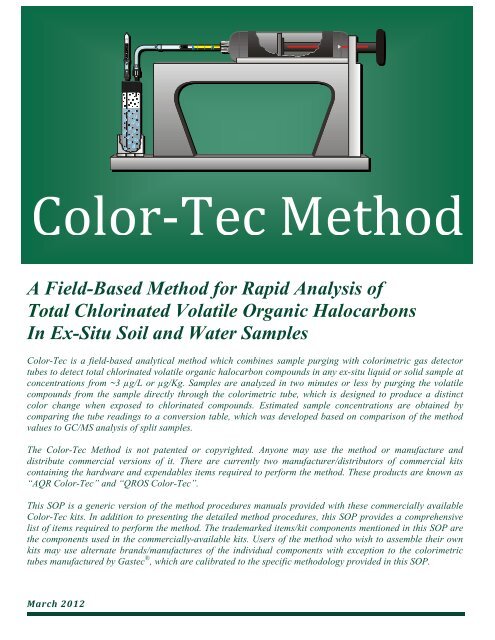
<strong>Color</strong>-<strong>Tec</strong> is a field-based analytical method which combines sample purging with colorimetric gas detector<br />
tubes to detect total chlorinated volatile organic halocarbon compounds in any ex-situ liquid or solid sample at<br />
concentrations from ~3 µg/L or µg/Kg. Samples are analyzed in two minutes or less by purging the volatile<br />
compounds from the sample directly through the colorimetric tube, which is designed to produce a distinct<br />
color change when exposed to chlorinated compounds. Estimated sample concentrations are obtained by<br />
comparing the tube readings to a conversion table, which was developed based on comparison <strong>of</strong> the method<br />
values to GC/MS analysis <strong>of</strong> split samples.<br />
The <strong>Color</strong>-<strong>Tec</strong> <strong>Method</strong> is not patented or copyrighted. Anyone may use the method or manufacture and<br />
distribute commercial versions <strong>of</strong> it. There are currently two manufacturer/distributors <strong>of</strong> commercial kits<br />
containing the hardware and expendables items required to per<strong>for</strong>m the method. These products are known as<br />
“AQR <strong>Color</strong>-<strong>Tec</strong>” and “QROS <strong>Color</strong>-<strong>Tec</strong>”.<br />
This SOP is a generic version <strong>of</strong> the method procedures manuals provided with these commercially available<br />
<strong>Color</strong>-<strong>Tec</strong> kits. In addition to presenting the detailed method procedures, this SOP provides a comprehensive<br />
list <strong>of</strong> items required to per<strong>for</strong>m the method. The trademarked items/kit components mentioned in this SOP are<br />
the components used in the commercially-available kits. Users <strong>of</strong> the method who wish to assemble their own<br />
kits may use alternate brands/manufactures <strong>of</strong> the individual components with exception to the colorimetric<br />
tubes manufactured by Gastec ® , which are calibrated to the specific methodology provided in this SOP.<br />
March 2012
Ambient air enters<br />
the sample through<br />
a carbon filter<br />
Filtered ambient air<br />
flows through the<br />
long purge needle<br />
to the bottom <strong>of</strong><br />
the VOA vial<br />
Ambient air purges<br />
and strips volatile<br />
compounds from<br />
the sample<br />
<strong>Color</strong>-<strong>Tec</strong> <strong>Method</strong><br />
Standard Operating Procedures<br />
2 5 6<br />
3<br />
4<br />
The purged chlorinated<br />
volatile compounds are<br />
directed into the gas<br />
detector tube<br />
1<br />
A measured color change in<br />
the colorimetric tube is used<br />
to estimate the expected<br />
concentration <strong>of</strong> CVOHs in<br />
the sample<br />
The piston-pump<br />
provides vacuum air<br />
flow that purges the<br />
sample and pulls the<br />
chlorinated volatile<br />
vapor through the tube<br />
� <strong>Color</strong>-<strong>Tec</strong> combines sample purging with direct-read gas detector tubes to<br />
quickly detect low-levels <strong>of</strong> chlorinated compounds in liquid and solid samples.<br />
� <strong>Color</strong>-<strong>Tec</strong> detects concentrations <strong>of</strong> total chlorinated volatile organic<br />
halocarbons (CVOHs) below 3 µg/L in water and 3 µg/Kg in soil samples.<br />
1<br />
� <strong>Color</strong>-<strong>Tec</strong> provides fast, low-level, economical, decision-quality data which<br />
maximizes sampling frequency and sampling coverage to locate source areas<br />
and delineate dissolved-phase contaminant plumes.<br />
� Samples are analyzed by purging the volatile compounds from either liquid or<br />
solid samples through a colorimetric detector tube, which produces a distinct<br />
color change when exposed to any chlorinated compound.<br />
� The <strong>Color</strong>-<strong>Tec</strong> tube response (tube reading) is compared to a conversion table<br />
to provide an estimate <strong>of</strong> the expected sample concentration in µg/L <strong>for</strong> water<br />
and µg/Kg <strong>for</strong> soil samples.
Section Page<br />
Table <strong>of</strong> Contents<br />
1.0 <strong>Method</strong> History and Principles 2<br />
2.0 <strong>Color</strong>-<strong>Tec</strong> Test Kit Parts Description and Set-Up 3<br />
2.1 Materials 3<br />
2.1.1 Hardware 3<br />
2.1.2 Expendables 3<br />
Figure 1 - Hardware Kit Parts 3<br />
Figure 2 - 10-Sample Expendables Pack Parts 4<br />
2.2 Additional Supplies 4<br />
2.3 Storage & Stability <strong>of</strong> <strong>Color</strong>imetric Tubes 4<br />
2.4 Heating <strong>Color</strong>imetric Tubes and Samples 4-5<br />
2.5 Carbon Pre-Filter 5<br />
2.6 <strong>Color</strong>-<strong>Tec</strong> Workstation Set-Up 5-6<br />
3.0 Sample Collection and Preparation 7<br />
3.1 Liquid Sample Media 7<br />
3.2 Solid Sample Media 7<br />
3.3 Purpose <strong>of</strong> the Second VOA Vial 7<br />
4.0 Sample Analysis Procedure 8-9<br />
Important Procedural Notes 9<br />
Troubleshooting Guide 10<br />
5.0 Sample Purging and Detection <strong>Method</strong>ology 11<br />
5.1 50cc Purge 11<br />
5.2 100cc Purge 11<br />
5.3 200cc Purge 11<br />
Table 1 - Purge Volume Correction Factors 12<br />
6.0 Reading the Tubes 12<br />
6.1 Very Low Concentrations 12<br />
6.2 Low to Medium Concentrations 12<br />
6.3 High Concentrations 13<br />
6.4 Recording Tube Readings 13<br />
7.0 Estimating Sample Concentrations (Conversion Table) 13<br />
Table 2 – Conversion Table 14<br />
8.0 Proposed QA/QC Procedures 15<br />
8.1 Analytical Confidence and <strong>Method</strong> Per<strong>for</strong>mance 15<br />
8.2 Chemical Inhibitors (False Negatives) 15<br />
8.3 Positive Interference (False Positives) 15-16<br />
Chlorinated Volatile Organic Halocarbons 16<br />
Water Vapor 16<br />
Hydrogen Chloride Vapor 16<br />
Free Chlorine 16<br />
Contaminant Carryover 16<br />
8.4 Ambient Air Interference 16<br />
8.5 Duplicate Sample Testing Procedure 16<br />
8.6 Collection <strong>of</strong> Split Samples <strong>for</strong> Laboratory Analysis 17<br />
9.0 Safety Precautions and Disposal <strong>of</strong> Expendable Materials 17-18<br />
Product Warranty 18<br />
EPA Guidance and Case Studies Featuring the <strong>Color</strong>-<strong>Tec</strong> <strong>Method</strong> 18<br />
Recommended Field Applications <strong>for</strong> the <strong>Color</strong>-<strong>Tec</strong> <strong>Method</strong> 19<br />
2
1.0 <strong>Method</strong> History and Principles<br />
The <strong>Color</strong>-<strong>Tec</strong> method was developed during 1997 by the environmental pr<strong>of</strong>essionals at Ecology<br />
and Environment, Inc. while assessing/remediating the earliest sites addressed under the Florida<br />
Department <strong>of</strong> Environmental Protection’s (FDEP) Drycleaning Solvent Cleanup Program. Since its<br />
development, the method has been used extensively at EPA, DOD, and various state regulatory<br />
agency sites to provide real-time, decision quality data at thousands <strong>of</strong> chlorinated solvent sites.<br />
<strong>Color</strong>-<strong>Tec</strong> is a field-based analytical method which combines the use <strong>of</strong> colorimetric gas detector<br />
tubes (originally designed <strong>for</strong> occupational breathing-zone monitoring) with sample purging to<br />
detect very low (
2.0 <strong>Color</strong>-<strong>Tec</strong> Test Kit Description and Set-up<br />
The <strong>Color</strong>-<strong>Tec</strong> Chlorinated VOH Soil/Water Test Kit System consists <strong>of</strong> two primary components:<br />
1. A hardware kit which contains all reusable equipment needed to conduct the method, plus<br />
an optional carrying case; and<br />
2. Expendables kits containing all disposable components needed <strong>for</strong> analysis <strong>of</strong> 10 water or<br />
soil samples using one <strong>of</strong> four available ranges <strong>of</strong> Gastec ® 133-series tubes:<br />
a. Ultra low range 133-LL tubes (expected detection range ~ 3 to 1200 µg/L or µg/Kg)<br />
b. Low range 133-L tubes (expected detection range ~ 75 to 25,000 µg/L or µg/Kg)<br />
c. Medium range 133-M tubes (expected detection range ~ 500 to 130,000 µg/L or µg/Kg)<br />
d. High range 133-HA tubes (expected detection range ~ 5000 to 2,300,000 µg/L or µg/Kg)<br />
2.1 Materials<br />
2.1.1 <strong>Color</strong>-<strong>Tec</strong> Hardware (See Figure 1)<br />
Item<br />
Gastec ® Piston pump<br />
<strong>Color</strong>-<strong>Tec</strong> Pump Stand<br />
Corning ® Hot Plate<br />
Stainless Steel Heating Pan<br />
Nalgene ® VOA Heating Rack<br />
Thermometer<br />
Decontamination Syringe<br />
Pelican ® hard case<br />
2.1.2 <strong>Color</strong>-<strong>Tec</strong> Expendables (See Figure 2)<br />
Item Quantity Per Analysis<br />
<strong>Color</strong>imetric Detector Tubes (133-LL, L, M, or HA) 1 per range, depending on concentration<br />
Disposable Extraction Needle Assemblies (single use only) 1<br />
Carbon Filter (may be re-used) 1 <strong>for</strong> every 10 to 20 samples or more<br />
Carbon Filter Assembly (may be re-used) 1 <strong>for</strong> every 10 to 20 samples or more<br />
Purge Needle (may be re-used) 1 (must be cleaned between each use)<br />
40 Milliliter unpreserved VOA Vials (single use only) 2<br />
Figure 1<br />
Required Hardware<br />
4<br />
Figure 2<br />
Expendables <strong>for</strong> 10 Analyses
2.2 Additional Supplies<br />
The following items are suggested <strong>for</strong> use with the <strong>Color</strong>-<strong>Tec</strong> method to per<strong>for</strong>m the listed<br />
functions.<br />
Item Purpose<br />
Organic-free water <strong>for</strong> soil sample extraction and equipment decontamination<br />
Safety gloves personal protection<br />
Safety glasses personal protection<br />
120V AC power source <strong>for</strong> hot plate<br />
Permanent marker labeling sample bottles<br />
40 Milliliter VOA Vials (Optional Item) <strong>for</strong> <strong>Color</strong>-<strong>Tec</strong> analysis and split samples<br />
Per<strong>for</strong>mance <strong>of</strong> the <strong>Color</strong>-<strong>Tec</strong> method requires the use <strong>of</strong> two standard, unpreserved VOA vials per<br />
sample. These VOA vials are not included in the standard expendables kits, but may be added as<br />
an option. The user may wish to collect a quantity <strong>of</strong> split samples <strong>for</strong> laboratory analysis to provide<br />
comparison data which may be used to determine site-specific method detection limits and/or to<br />
tentatively quantify <strong>Color</strong>-<strong>Tec</strong> results. Split sampling will likely require three pre-preserved VOA<br />
vials per sample. Pre-preserved VOA vials <strong>for</strong> split samples are not available in the <strong>Color</strong>-<strong>Tec</strong><br />
expendables kits.<br />
2.3 Storage & Stability <strong>of</strong> <strong>Color</strong>imetric Tubes<br />
The Gastec ® colorimetric tubes have a shelf-life <strong>of</strong> two years with refrigeration. Tubes should be<br />
stored at or below a temperature <strong>of</strong> 10°C/50°F when not in use. <strong>Color</strong>imetric detector tubes are<br />
single-use (one tube per analysis) and should be used immediately after the tips are broken. Tube<br />
readings should be recorded immediately following analysis because the intensity <strong>of</strong> the colorchange<br />
fades over time. Each box <strong>of</strong> tubes has an expiration date printed in red ink on the top <strong>of</strong><br />
each box. When heating the tubes <strong>for</strong> use with the <strong>Color</strong>-<strong>Tec</strong> method, it is recommended that the<br />
tube temperature does not exceed 40°C/104° F. Other procedures and guidelines associated with<br />
the use <strong>of</strong> the tubes <strong>for</strong> their designed purpose (gas detection in ambient air) are included in the<br />
tube manufactures data sheets and tube instructions included in the tube packaging.<br />
2.4 Heating <strong>Color</strong>imetric Tubes and Samples<br />
The colorimetric gas detector tubes used in the <strong>Color</strong>-<strong>Tec</strong> method were designed <strong>for</strong> the purpose <strong>of</strong><br />
detecting volatile organic compounds (CVOHs) in ambient air. When using the tubes <strong>for</strong> analysis <strong>of</strong><br />
ambient air, the calibrated operating temperature is 20°C/68°F. Using the tubes at temperatures<br />
above or below 20°C/68°F, <strong>for</strong> the purpose <strong>of</strong> testing ambient air, introduces error into the<br />
measurements requiring application <strong>of</strong> correction factors to correct that error. Because <strong>Color</strong>-<strong>Tec</strong><br />
is an alternate use <strong>of</strong> the colorimetric tubes which concentrates CVOHs from water or soil<br />
samples into the tubes, the units (ppmV) printed on the tubes have no direct relationship to<br />
the quantity <strong>of</strong> CVOHs dissolved in the water/soil sample being analyzed and the<br />
temperature correction factors used <strong>for</strong> analysis <strong>of</strong> ambient air are not required when using<br />
the colorimetric tubes as part <strong>of</strong> the <strong>Color</strong>-<strong>Tec</strong> method. However, since the colorimetric tubes<br />
are more sensitive to the presence <strong>of</strong> chlorinated compounds at 40°C/104°F, and the purpose <strong>of</strong><br />
the <strong>Color</strong>-<strong>Tec</strong> method is to detect the presence/absence <strong>of</strong> CVOHs in water at concentrations at the<br />
lowest concentrations possible, the tubes are heated to their optimum sensitivity (40°C/104°F) to<br />
maximize their detection capability.<br />
5
The samples are also heated (in the VOA vials) to maximize contaminant volatilization and transfer<br />
<strong>of</strong> CVOHs from the water sample to the colorimetric tube. To heat the samples and colorimetric<br />
tubes, a hot plate is used to heat a water bath containing a test tube rack to hold the sample-filled<br />
VOA vials and unbroken colorimetric tubes. Special attention must be paid to the temperature <strong>of</strong><br />
the water to avoid prolonged overheating the samples and tubes. The samples and colorimetric<br />
tubes should not be heated in excess <strong>of</strong> 40°C/104°F.<br />
Given the size <strong>of</strong> the heating pan and VOA rack, generally only 3 sets <strong>of</strong> samples are heated at the<br />
same time. When a pair <strong>of</strong> VOAs is removed from the heating rack and placed on the pump stand,<br />
it can be replaced with a new pair <strong>for</strong> heating. After collection, samples should remain in a cool<br />
place until ready to be heated and analyzed. It is recommended to avoid heating the samples <strong>for</strong><br />
more than about 2 minutes to avoid loss <strong>of</strong> CVOCs. Section 2.6 below, provides detailed water bath<br />
set-up and heating procedures.<br />
2.5 Carbon Pre-Filter<br />
Because ambient air is used to purge the samples, a carbon pre-filter is provided <strong>for</strong><br />
attachment to the purge needle to prevent volatile airborne contaminants from passing<br />
through the sample and entering the detector tube during the purging process. To use<br />
the carbon pre-filter, break both tips <strong>of</strong> a carbon filter tube and insert the end <strong>of</strong> the tube<br />
onto the carbon lure assembly (make sure the air-flow arrows on the carbon tube point<br />
toward the carbon lure assembly), then tightly insert the male lure fitting on the carbon<br />
lure assembly into the female lure fitting on the purge needle (see Figure 2). At sites<br />
where little or no ambient air contamination is expected, a single pre-filter tube may be<br />
reused <strong>for</strong> several days. However, at sites where high concentrations <strong>of</strong> airborne<br />
chlorinated compounds are suspected or have been confirmed in the ambient air, the<br />
pre-filter tubes may need to be replaced more frequently. For most situations, one<br />
carbon filter per 10 samples is more than sufficient. Section 2.6 below, provides detailed<br />
carbon filter set-up and use procedures.<br />
2.6 <strong>Color</strong>-<strong>Tec</strong> Work-Station Set-up<br />
Pump Stand Set-up<br />
1. Place the pump stand up-right on a flat stable surface.<br />
2. Place the ® piston-pump into the curved tray on the<br />
top <strong>of</strong> the pump stand as shown in the photo.<br />
Corning ® Hot Plate Set-up<br />
1. Connect the AC power cord to the back <strong>of</strong> the hot plate.<br />
2. Connect the other end <strong>of</strong> the AC power cord to a USA 120VAC<br />
electric outlet.<br />
3. Place the hot plate on a flat stable surface.<br />
4. Set the hot plate thermostat control to between dial setting 4 and 5.<br />
6
Hot Water Bath Set-up<br />
1. Fill the stainless-steel water bath pan with tap water to<br />
approximately 1.5-inches from the rim.<br />
2. Insert the VOA rack into the water-filled, stainless-steel, water bath<br />
pan.<br />
3. Remove the cap from a 40ml VOA vial, fill the VOA vial with tap<br />
water and place it into the VOA Rack as shown in the photo. Note:<br />
The bottom <strong>of</strong> the water-filled VOA vial should be slightly submersed in the water in the<br />
stainless-steel pan.<br />
4. Place the stainless-steel water bath pan onto the heating surface <strong>of</strong> the hot-plate.<br />
5. Open a box <strong>of</strong> low-level (133LL) Gastec ® tubes and place several tubes into the water-filled<br />
VOA vial. Insert the yellow reagent end <strong>of</strong> the tubes into the bottom <strong>of</strong> the VOA vial. Note:<br />
Do not place tubes with broken tips in the water bath – heating must be accomplished<br />
be<strong>for</strong>e breaking the tube tips.<br />
6. Turn on the Oakton ® digital thermometer and insert the steel probe <strong>of</strong> the thermometer into<br />
the water-filled VOA vial with the colorimetric tubes. Maintain the water in the VOA vial<br />
containing the colorimetric tubes at approximately 100ºF. The temperature <strong>of</strong> the water bath<br />
pan may be maintained slightly higher than the water in the VOA vial containing the<br />
colorimetric tubes to facilitate faster heating <strong>of</strong> the samples. Replace any water that<br />
evaporates from the water bath pan or the VOA vial containing the colorimetric tubes.<br />
Heating Samples<br />
1. Place both VOA vials containing the sample into the hot water bath <strong>for</strong> approximately 1 to 2<br />
minutes.<br />
2. Be sure that the VOA vials are tightly sealed be<strong>for</strong>e heating. Note: When properly heated,<br />
the VOA vials should feel warm in the hand – DO NOT OPEN VOA VIALS AFTER<br />
HEATING.<br />
Carbon Filter/Purge Needle Set-up<br />
1. Break both ends <strong>of</strong> a carbon filter tube using the tip breaker on the<br />
piston pump.<br />
2. Connect a carbon filter luer assembly to the carbon filter tube by sliding<br />
the open end <strong>of</strong> the vinyl tubing over the broken end <strong>of</strong> the carbon filter<br />
tube. Note: The carbon filter is re-used <strong>for</strong> multiple purge cycles.<br />
3. Attach the carbon filter assembly to a purge needle by inserting the<br />
carbon filter assembly luer fitting into the purge needle luer fitting.<br />
4. The purge needle (with carbon filter) is now ready to use. Follow the<br />
steps in Section 4 to conduct sample analysis. Important Note: Do not<br />
insert the purge needle into the sample VOA be<strong>for</strong>e completing<br />
steps 5 and 6 <strong>of</strong> Section 4.<br />
7
3.0 Sample Collection and Preparation<br />
3.1 Liquid Sample Media<br />
Collect the water or other liquid sample media directly from your sampling<br />
device into two 40 ml VOA vials by filling each vial to ~75% capacity (i.e.<br />
to about 1-inch below the shoulder <strong>of</strong> each vial). Tightly secure the caps<br />
onto the partially-filled VOA vials. The VOA vials containing the liquid<br />
sample to be tested must contain an air-filled headspace to<br />
accommodate purging. The caps must be tightened sufficiently to<br />
prevent loss <strong>of</strong> CVOHs during the time between sample collection and<br />
analysis (which includes the heating process) and to prevent air leakage<br />
during the purging process.<br />
3.2 Solid Sample Media<br />
Place about 1.5 inches <strong>of</strong> soil (or other solid sample media) into the<br />
bottom <strong>of</strong> each <strong>of</strong> two VOA vials (i.e. approximately 30 grams in each vial). Immediately after<br />
inserting the soil (or other solid sample media) into the two vials, add organic-free or other “clean”<br />
water to each VOA vial until they are both ~70 % full (i.e. to approximately 1-inch below the<br />
shoulder <strong>of</strong> each vial). Tightly secure the caps onto the partially-filled VOA vials. Once the caps are<br />
secure, shake the VOA vials vigorously <strong>for</strong> approximately <strong>for</strong> 5 to 10<br />
seconds to thoroughly mix the soil and water.<br />
Additional mixing may be necessary <strong>for</strong> soil<br />
matrices comprised <strong>of</strong> clay-sized particles. The<br />
purpose <strong>of</strong> the mixing is to transfer any chlorinated<br />
compounds suspended in the soil matrix to the<br />
water to facilitate more effective purging.<br />
IMPORTANT NOTE: The VOA vials containing the<br />
solid sample media and “clean” water must contain<br />
an air-filled headspace to accommodate purging.<br />
The caps must be tightened sufficiently to prevent<br />
loss <strong>of</strong> CVOHs during the time between sample<br />
collection and analysis (which includes the heating<br />
process) and to prevent air leakage during the<br />
purging process.<br />
3.3 Purpose <strong>of</strong> the Second VOA Vial<br />
The <strong>Color</strong>-<strong>Tec</strong> method is designed <strong>for</strong> use with two VOA vials (an original and a duplicate) <strong>for</strong> each<br />
sample collected. In certain situations, the duplicate sample may not be used in the per<strong>for</strong>mance <strong>of</strong><br />
the method. However, the duplicate sample should always be collected in the event that it is<br />
needed to complete the analysis process. The duplicate sample may be used in either <strong>of</strong> the<br />
following situations:<br />
1. When the initial test does not induce a color change in the colorimetric tube, the second<br />
VOA vial containing the duplicate sample, may be purged (using the same colorimetric tube)<br />
to increase the probability <strong>of</strong> detecting very low (< 10 µg/L) concentrations.<br />
2. When the initial test induces a color change that exceeds the<br />
upper limit <strong>of</strong> the LL tube (a tube reading >3 <strong>for</strong> 100cc purge or<br />
>9 <strong>for</strong> 50cc purge), the extra VOA vial can be used to analyze<br />
the sample using higher range colorimetric tubes (133L or 133M)<br />
to tentatively quantify the higher concentration <strong>of</strong> chlorinated<br />
compounds in the sample.<br />
8
4.0 Sample Analysis Procedure<br />
1. Place both heated VOA vials (original & duplicate sample) into the<br />
two VOA holders on the pump-stand.<br />
2. Remove a low-level tube from the hot water bath and wipe it dry.<br />
3. Break both ends <strong>of</strong> the colorimetric tube<br />
using the tip breaker on the piston pump.<br />
4. Insert the colorimetric tube into the pump<br />
inlet with the flow arrow (printed on the tube)<br />
toward the pump. Note: Tube orientation is<br />
critical – the yellow reagent end <strong>of</strong> the tube<br />
is inserted in the pump.<br />
5. Connect a new extraction needle assembly to the colorimetric tube by sliding the open end<br />
<strong>of</strong> the vinyl tubing over the broken end <strong>of</strong> the colorimetric tube. This step must be<br />
completed be<strong>for</strong>e inserting the needle into the VOA (Prior to step 6).<br />
6. Remove the protective cap from the extraction needle and insert<br />
the needle into the septa <strong>of</strong> the first VOA vial. Note: Be sure that<br />
the tip <strong>of</strong> the extraction needle is positioned within the headspace<br />
<strong>of</strong> the VOA vial (above the water level). Do not insert the<br />
extraction needle as far as it will go into the headspace <strong>of</strong> the<br />
VOA vial, but rather only to a point slightly beneath the inside <strong>of</strong><br />
the septa to reduce the possibility <strong>of</strong> sample water entering the<br />
extraction needle assembly and colorimetric tube during the<br />
purging process.<br />
7. Insert the purge needle (with carbon filter assembly) into the<br />
septa <strong>of</strong> the first VOA vial and push the tip <strong>of</strong> the needle to the<br />
bottom <strong>of</strong> the VOA vial.<br />
IMPORTANT NOTE: Do not insert the purge needle be<strong>for</strong>e<br />
completing steps 5 and 6.<br />
8. Align the 50ml label and red dot on the pump handle with the red<br />
dot on the pump shaft.<br />
9. Pull the handle sharply until it locks in the 50ml (half pull) position.<br />
10. Confirm that air is purging through the sample in the VOA vial.<br />
11. Purge <strong>for</strong> approximately 30 seconds.<br />
12. Check the yellow reagent in the tube <strong>for</strong> a colorchange.<br />
13. If no color-change reaction is visible or if the color<br />
reading is less than 1.5, rotate the pump handle<br />
½ turn and pull the handle out to lock in the<br />
100ml position.<br />
9
14. Continue the 100ml purge until the flow cycle is complete. Note:<br />
Flow is complete when the end-<strong>of</strong>-flow indicator (located on the<br />
back <strong>of</strong> the pump handle) returns to its full brightness.<br />
15. Check the yellow reagent phase in the tube <strong>for</strong> a color change.<br />
16. If no color-change is visible, remove the extraction needle from the<br />
VOA with the vinyl tubing still attached to the low-level tube, rotate<br />
the pump handle ¼ turn and push the plunger back into the pump, remove the extraction<br />
needle from the first VOA vial and inject it into the septa <strong>of</strong> the second VOA (duplicate<br />
sample), then remove the purge needle from the first VOA vial and inject it into the septa <strong>of</strong><br />
the second VOA (duplicate sample) - now re-pull the pump handle to lock into the 100ml<br />
position.<br />
17. When the second 100ml purge cycle is complete, read and record the results.<br />
For samples containing high concentrations (>150 µg/L) the resulting color-change may exceed the<br />
calibrated limit <strong>of</strong> the low-level tube, requiring the second VOA vial (duplicate sample) to be purged<br />
and analyzed by repeating steps 3 through 13 using a medium range (133L) or a high range (133M)<br />
tube.<br />
For samples containing low (10 µg/L) <strong>of</strong> chlorinated compounds, the resulting color change is an<br />
obvious light to dark purple, which propagates through the yellow reagent layer toward the pump<br />
end <strong>of</strong> the colorimetric tube. The tube reading (<strong>Color</strong>-<strong>Tec</strong> response) is obtained by matching the<br />
linear extent <strong>of</strong> the discolored reagent inside the tube to the calibration scale printed on the outside<br />
<strong>of</strong> the tube. Table 1 presents a troubleshooting matrix with causes and solutions potential problems.<br />
Important Procedural Notes:<br />
The disposable extraction needle assembly is intended <strong>for</strong> one use only. Decontamination and reuse<br />
<strong>of</strong> this part is highly discouraged because <strong>of</strong> the risk <strong>of</strong> contaminant carryover from the tubing<br />
and other plastic parts which can harbor contaminants from the previous analysis. Purge needles<br />
may be reused following decontamination using water and isopropanol.<br />
Carbon filters should be discarded if they become wet from contact with sample water.<br />
Never insert the purge needle into the VOA be<strong>for</strong>e the extraction needle assembly has first been<br />
connected to the colorimetric tube and inserted into the VOA headspace. If the purge needle is<br />
inserted first, the pressure inside the sealed VOA may <strong>for</strong>ce sample water up though the purge<br />
needle and into the carbon filter. Sample volatiles may be lost if the extraction needle assembly is<br />
inserted into the VOA headspace be<strong>for</strong>e connecting the tubing to the colorimetric tube.<br />
To prevent clogging <strong>of</strong> the purge needle when inserting the purge needle into VOA vials containing<br />
soil samples, do not immediately push the bottom <strong>of</strong> the needle through the soil to the bottom <strong>of</strong> the<br />
vial; but rather temporarily position the base <strong>of</strong> the purge needle in the water above the soil until the<br />
pump handle has been pulled to begin air flow through the sample. Once air flow has been initiated,<br />
slowly extent the purge needle through the soil to the base <strong>of</strong> the vial. The air flow from the tip <strong>of</strong><br />
the purge needle should reduce the potential <strong>for</strong> clogging as the needle moves through the soil.<br />
This procedure is especially helpful when working with clayey soils.<br />
10
Troubleshooting Guide<br />
Problem Possible Cause Solution<br />
Sample does not<br />
appear to be purging<br />
(bubbling) after the<br />
pump handle has<br />
been pulled.<br />
The colorimetric tube<br />
shows no reaction<br />
after purging a<br />
sample that contains<br />
chlorinated<br />
compounds.<br />
(False Negative)<br />
The colorimetric tube<br />
indicates a reaction<br />
after purging a<br />
sample that contains<br />
no chlorinated<br />
compounds.<br />
(False Positive)<br />
Clogged/blocked purge<br />
needle (long needle).<br />
Clogged/blocked extraction<br />
needle (short needle).<br />
<strong>Color</strong>imetric tube is not<br />
securely connected to hand<br />
pump.<br />
<strong>Color</strong>imetric tube is not<br />
securely connected to<br />
extraction needle tubing.<br />
VOA cap is not tightly sealed.<br />
<strong>Color</strong>imetric tube tips were<br />
not broken be<strong>for</strong>e connecting<br />
to hand pump and tubing.<br />
Broken/bad plunger seal in<br />
hand pump.<br />
<strong>Color</strong>imetric tube is below<br />
the optimum operating<br />
temperature.<br />
<strong>Color</strong>imetric tube was<br />
connected using reversed<br />
flow direction.<br />
The sample also contains a<br />
detectable concentration <strong>of</strong><br />
xylenes or toluene.<br />
Chlorinated compounds are<br />
present at detectable<br />
concentrations the ambient<br />
air.<br />
HCl vapor is present in the<br />
sample VOA or in the<br />
ambient air.<br />
Water vapor has entered the<br />
yellow reagent phase <strong>of</strong> the<br />
tube indicating a positive<br />
reaction<br />
Use the decontamination syringe to check the purge<br />
needle <strong>for</strong> clogs. If clogged, clean the needle or use a<br />
new purge needle.<br />
Use decontamination syringe to check the extraction<br />
needle <strong>for</strong> clogs. Use decontamination syringe to clean<br />
the needle or use a new extraction needle.<br />
Remove and re-insert the colorimetric tube from the hand<br />
pump. If the fit seems loose, replace the hand pump inlet<br />
gasket.<br />
Check the connection between the extraction needle<br />
tubing and the colorimetric tube. If loose, insert the<br />
colorimetric tube further into the extraction needle tubing.<br />
Check the tightness <strong>of</strong> the VOA cap. Tighten if<br />
necessary.<br />
Break both tips <strong>of</strong> the colorimetric tube be<strong>for</strong>e connecting<br />
to hand pump and tubing.<br />
Check the pump seal by holding your finger over the<br />
hand pump inlet while pulling the pump handle and lock<br />
into the 50cc position. If no vacuum is apparent, open the<br />
pump, remove the plunger, replace the plunger seal, and<br />
grease the new seal. Re-assemble the pump.<br />
Heat the colorimetric tube to 40°C/104° F be<strong>for</strong>e using. It<br />
is also recommended to heat the sample. The<br />
recommended temperature <strong>for</strong> tubes and samples when<br />
using the <strong>Color</strong>-<strong>Tec</strong> <strong>Method</strong> is 40°C/104° F.<br />
Use the flow direction arrows to properly align the tube.<br />
The purged air must pass through the black oxidizer<br />
phase and the white catalyst phase be<strong>for</strong>e entering the<br />
yellow reagent phase.<br />
Samples can be tested <strong>for</strong> the presence <strong>of</strong> xylenes and<br />
toluene using the Gastec ® 122L colorimetric tube. The<br />
detection <strong>of</strong> chlorinated compounds may be diminished<br />
when xylenes or toluene are present in a sample.<br />
Test the ambient air using an LL tube to determine if<br />
chlorinated compounds are present at detectable<br />
concentrations. Attach the charcoal filter to the purge<br />
needle prior to purging samples.<br />
Avoid use <strong>of</strong> HCl in the area where <strong>Color</strong>-<strong>Tec</strong> is in use.<br />
Use only unpreserved VOAs <strong>for</strong> samples to be screened<br />
with <strong>Color</strong>-<strong>Tec</strong>.<br />
Avoid purging more than 200 CCs through any sample.<br />
Stop purging be<strong>for</strong>e condensation inside the tube<br />
reaches the end <strong>of</strong> the black oxidizer phase. Avoid<br />
drawing any water from the sample VOA into the<br />
colorimetric tube.<br />
11
5.0 Sample Purging and Detection <strong>Method</strong>ology<br />
Samples may be purged using 50 cubic centimeters (cc), 100cc, or 200cc purge volumes. These<br />
various purge volumes are used in succession to maximize the low-level detection capability and<br />
detection range <strong>of</strong> each tube, thereby reducing the number <strong>of</strong> tubes needed to tentatively quantify<br />
the concentration <strong>of</strong> total chlorinated compounds in the sample. The pump stand is equipped with<br />
two VOA-vial holders to accommodate a second (duplicate) sample to be collected from each<br />
sampling location. This duplicate sample (collected and prepared in the same manner as the<br />
original sample) serves the following two potential purposes:<br />
1. When purging the initial VOA vial does not induce a color change in the colorimetric tube,<br />
the second VOA vial containing the duplicate sample, may be purged (using the same<br />
colorimetric tube) to increase the probability <strong>of</strong> detecting very low (< 10 µg/L)<br />
concentrations.<br />
2. When the initial test induces a color change that exceeds the upper limit <strong>of</strong> the LL tube (a<br />
tube reading > 3), the extra VOA vial can be used to analyze the sample using higher range<br />
colorimetric tubes (133L or 133M) to tentatively quantify the higher concentration <strong>of</strong><br />
chlorinated compounds in the sample.<br />
5.1 50cc Purge Volume<br />
Initially, all samples are analyzed using a Gastec ® 133-LL tube with a 50cc purge cycle. If the 50cc<br />
purge induces a color change reading <strong>of</strong> 1.5 to 3.0, read the calibration scale value aligned with the<br />
stained/unstained interface in the tube and use the pump stroke correction factors provided on<br />
Table 1 to determine the correct reading <strong>for</strong> a 50cc purge volume. If the concentration in the sample<br />
exceeds the upper detection limit <strong>of</strong> the tube (i.e. the color change moves beyond the upper limit <strong>of</strong><br />
the calibration scale printed on the tube), repeat the analysis using duplicate samples and higher<br />
range tubes (133-L, 133-M, and 133-HA) until the color change reaction stops within the calibration<br />
scale on the tube. If the color change reaction exceeds the upper limit <strong>of</strong> the calibration scale <strong>of</strong> the<br />
HA tube, the sample contains a concentration <strong>of</strong> chlorinated compounds above the upper detection<br />
capability <strong>of</strong> the <strong>Color</strong>-<strong>Tec</strong> <strong>Method</strong>.<br />
5.2 100cc Purge Volume<br />
Following completion <strong>of</strong> the 50cc purge cycle, if the concentration in the sample has induced a color<br />
change in the tube which traveled less than half the distance <strong>of</strong> the calibrated portion <strong>of</strong> the reagent<br />
phase <strong>of</strong> the tube (less than a reading <strong>of</strong> approximately 1.5), pull the pump handle outward and lock<br />
it into the 100cc position to complete a full purge cycle. Record the value aligned with the<br />
stained/unstained interface on the tube. No correction factor is needed <strong>for</strong> a 100cc purge.<br />
5.3 200cc Purge Volume<br />
Following completion <strong>of</strong> the 100cc purge cycle, if the concentration in the sample has induced no<br />
color change reaction, remove the purge needle and extraction needle assembly from the VOA vial<br />
containing the original sample and insert them into the VOA vial containing the duplicate sample<br />
(which has also been pre-heating) and per<strong>for</strong>m another 100cc purge cycle using the same<br />
colorimetric tube. To per<strong>for</strong>m the transfer to the second vial, remove both needles from the<br />
original VOA vial and immediately insert both needles into the septa <strong>of</strong> the duplicate sample VOA<br />
vial. Be<strong>for</strong>e re-inserting the pump handle, temporarily remove the colorimetric tube from the tip <strong>of</strong><br />
the hand pump and re-insert the pump handle completely into the pump while the tube is unattached.<br />
Re-attach the colorimetric tube into the pump tip and pull the pump handle and lock it into<br />
the 100cc position. Following the complete second purge cycle, read the calibration scale value<br />
aligned with the stained/unstained interface in the tube and use the pump stroke correction factors<br />
provided on Table 1 to determine the correct reading <strong>for</strong> a 200cc purge volume.<br />
12
Table 1<br />
Purge Volume Correction Factors <strong>for</strong> 133-Series Tubes<br />
<strong>Color</strong>imetric<br />
Tube<br />
6.0 Reading the Tubes<br />
Purge<br />
Volume<br />
Quantity <strong>of</strong><br />
Pump Pulls<br />
13<br />
Correction Factor<br />
133-LL 50cc Half Pull Tube Reading x 3<br />
133-LL 100cc Full Pull Tube Reading x 1<br />
133-LL 200cc Two Pulls Tube Reading x 0.5<br />
133-L 50cc Half Pull Tube Reading x 3<br />
133-L 100cc Full Pull Tube Reading x 1<br />
133-L 200cc Two Pulls Tube Reading x 0.5<br />
133-M 50cc Half Pull Tube Reading x 2.5<br />
133-M 100cc Full Pull Tube Reading x 1<br />
133-M 200cc Two Pulls Tube Reading x 0.4<br />
133-HA 50cc Half Pull Tube Reading x 3<br />
133-HA 100cc Full Pull Tube Reading x 1<br />
133-HA 200cc Two Pulls Tube Reading x 0.3∞<br />
The basic <strong>Color</strong>-<strong>Tec</strong> method procedures are simple and intuitive;<br />
however, contaminant detection and semi-quantitative values are<br />
obtained through visual observation <strong>of</strong> the colorimetric reaction in the<br />
tubes, which is inherently subjective (especially in samples containing<br />
very low [
6.3 High Concentrations<br />
When the sample contains high concentrations (>100 µg/L) <strong>of</strong> chlorinated compounds, the color<br />
change reaction occurs quickly and usually exceeds the upper detection level <strong>of</strong> the Gastec ® 133LL<br />
tube. The higher the concentration <strong>of</strong> chlorinated compounds in the sample, the faster the color<br />
change reaction occurs and the further it propagates through colorimetric tube. Samples containing<br />
very high concentrations (>1000 µg/L) <strong>of</strong> chlorinated compounds, <strong>of</strong>ten discolor the entire yellow<br />
reagent layer in the LL tube be<strong>for</strong>e the pump handle has been fully extended. In these cases, the<br />
purging can be discontinued to allow <strong>for</strong> the current sample bottle to be re-tested using a higher<br />
range detector tube. There is no need to continue purging the sample when the detection level <strong>of</strong><br />
the tube is exceeded. Each subsequently higher range tube (133L, 133M, or 133HA) is used to<br />
purge each new duplicate sample in succession until the color change reaction does not exceed the<br />
calibration range <strong>of</strong> the tube being used.<br />
6.4 Recording Tube Readings<br />
It is recommended to record the observed concentration value (tube reading), the range <strong>of</strong> the<br />
colorimetric tube (LL, L, M, or HA) and the final purge volume when logging <strong>Color</strong>-<strong>Tec</strong> results. For<br />
example, a reading <strong>of</strong> 2.5 observed on an LL tube using a 100 ml purge should be recorded as<br />
2.5/LL/100. Purge volume correction factors must be applied <strong>for</strong> <strong>Color</strong>-<strong>Tec</strong> values which were<br />
obtained using any purge volume other than 100cc. For example, a reading <strong>of</strong> 0.2 observed on an<br />
LL tube using a 200 ml purge should be recorded as 0.1/LL/200. A reading <strong>of</strong> 60 observed on an M<br />
tube using a 50 ml purge should be recorded as 150/M/50.<br />
7.0 Estimating Sample Concentrations (Conversion Table)<br />
The <strong>Color</strong>-<strong>Tec</strong> reading (the distance that the color change travels through the tube) is a relative<br />
response to the amount <strong>of</strong> chlorinated-compound molecules that have been purged from the<br />
sample and directed into the tube. There<strong>for</strong>e, the units printed on the tubes are used only to record<br />
the relative response <strong>for</strong> each analysis in order to facilitate comparison to laboratory GC/MS<br />
methods.<br />
To provide a field-ready estimate <strong>of</strong> the total chlorinated solvent concentration in liquid and solid<br />
samples based on the colorimetric tube reading, The developer <strong>of</strong> the <strong>Color</strong>-<strong>Tec</strong> method created a<br />
conversion table (see Table 2) based on statistical comparison <strong>of</strong> water samples collected from<br />
chlorinated solvent sites in which the <strong>Color</strong>-<strong>Tec</strong> and GC/MS methods were used to analyze split<br />
samples. An estimated concentration may be obtained by matching the <strong>Color</strong>-<strong>Tec</strong> tube response to<br />
either the median expected GC/MS concentration or the range <strong>of</strong> expected GC/MS concentrations<br />
provided on the comparison table. The potential range <strong>of</strong> corresponding analytical values<br />
associated with each positive tube reading increases significantly as the sample concentration<br />
increases. The estimated concentrations presented on Table 2 represent the central tendency <strong>of</strong><br />
the comparison data. The actual analytical values obtained by laboratory analysis <strong>of</strong> split samples<br />
may differ substantially from this estimate and may fall outside <strong>of</strong> the corresponding ranges<br />
provided on Table 2.<br />
The expected GC/MS concentrations presented in Table 2 are based on comparison <strong>of</strong> water<br />
sample data only. These conversion values may also be used <strong>for</strong> soil data; however, the potential<br />
range in expected GC/MS concentrations may be increased as a result <strong>of</strong> the difference in soil<br />
volumes used in the two methods and in the inherent heterogeneity <strong>of</strong> most soil matrices. However,<br />
the potential deviation factors included in the range <strong>of</strong> expected GC/MS concentrations column<br />
should be sufficient to account <strong>for</strong> the intrinsic analytical variability <strong>of</strong> most soil sample results.<br />
THE COLOR-TEC TUBE READING IS NOT THE SAMPLE CONCENTRATION!<br />
The tube reading is a unit-less value which must be compared to laboratory results from split samples in<br />
order to yield an estimate <strong>of</strong> the actual concentration present in the sample. This conversion table<br />
provides a reasonable estimate <strong>of</strong> the expected sample concentration based on the tube reading.<br />
14
Table 2<br />
Conversion <strong>of</strong> <strong>Color</strong>-<strong>Tec</strong> Readings (Relative Responses) to<br />
Expected GC/MS Total Chlorinated Volatile Organic Halocarbon Concentrations<br />
Gastec ®<br />
<strong>Color</strong>imetric<br />
Tube<br />
133-LL<br />
133-L<br />
133-M<br />
133-HA<br />
<strong>Color</strong>-<strong>Tec</strong><br />
Tube Reading<br />
(relative response)<br />
(unit-less)<br />
Median Expected<br />
GC/MS (Laboratory)<br />
Concentration<br />
(µg/L or µg/kg)<br />
15<br />
Range <strong>of</strong> Expected GC/MS Concentrations<br />
(µg/L or µg/kg)<br />
Low High<br />
0 3 >0 5<br />
0.1 7 5 10<br />
0.2 15 10 20<br />
0.5 35 25 45<br />
0.8 55 40 75<br />
1 70 50 95<br />
1.5 110 75 140<br />
2 145 105 190<br />
2.5 190 130 245<br />
3 230 160 290<br />
5 380 260 490<br />
9 900 630 1,160<br />
25 2,500 1,250 3,750<br />
35 4,400 2,200 6,600<br />
45 7,700 3,850 11,550<br />
55 15,000 7,500 22,500<br />
75 17,200 8,600 25,800<br />
100 21,100 10,500 31,600<br />
200 46,000 23,000 69,000<br />
300 85,000 42,500 127,500<br />
500 225,500 112,800 338,300<br />
700 598,300 299,200 897,500<br />
900 1,587,500 793,800 2,381,300<br />
Notes:<br />
The <strong>Color</strong>-<strong>Tec</strong> Tube Reading (<strong>Color</strong>-<strong>Tec</strong> units) is the value printed on the colorimetric tube at the interface between the reacted and un-reacted<br />
reagent (the extent <strong>of</strong> the color change in the tube <strong>for</strong> a positive result).<br />
The Median Expected GC/MS Concentration is the estimated concentration in micrograms per liter (µg/L) <strong>of</strong> total chlorinated volatile organic<br />
halocarbons (CVOHs) present in the sample <strong>for</strong> the corresponding <strong>Color</strong>-<strong>Tec</strong> tube response.<br />
The Range <strong>of</strong> Expected GC/MS Concentrations is an estimated range <strong>of</strong> potential concentrations (µg/L or µg/kg) <strong>of</strong> total chlorinated volatile organic<br />
halocarbons (CVOHs) <strong>for</strong> the <strong>for</strong> the corresponding <strong>Color</strong>-<strong>Tec</strong> tube response.<br />
The Median Expected GC/MS Concentration was obtained using statistical comparison <strong>of</strong> <strong>Color</strong>-<strong>Tec</strong> <strong>Method</strong> data and GC/MS (EPA <strong>Method</strong> 8260B)<br />
data. Comparison data were obtained from 5348 water samples collected from 152 chlorinated solvent (primarily PCE) sites in which the <strong>Color</strong>-<strong>Tec</strong><br />
<strong>Method</strong> was used to analyze the samples in the field and either a laboratory-based or mobile GC/MS was used to analyze split samples.<br />
The Range <strong>of</strong> Expected GC/MS Concentrations reflects the potential deviation in the Median Expected GC/MS Concentration based on <strong>Color</strong>-<strong>Tec</strong><br />
<strong>Method</strong>/EPA <strong>Method</strong> 8260B comparison results. The potential error increases as the concentration increases. The initial deviation factor used <strong>for</strong> a<br />
<strong>Color</strong>-<strong>Tec</strong> Reading <strong>of</strong> zero is +/- 30% and increases to +/- 400% at a <strong>Color</strong>-<strong>Tec</strong> Reading <strong>of</strong> 900 units.<br />
The Median Expected GC/MS Concentrations presented in this table are based on comparison <strong>of</strong> water sample data only. These conversion values<br />
may also be used <strong>for</strong> soil data; however, the potential error or range in expected GC/MS concentrations may be increased as a result in the difference in<br />
soil volumes used in the two methods and in the inherent heterogeneity <strong>of</strong> many soil matrices. The potential deviation factors included in the Range <strong>of</strong><br />
Expected GC/MS Concentrations data should be sufficient to account <strong>for</strong> the intrinsic analytical variability <strong>of</strong> most soil sample results.<br />
The expected GC/MS concentrations in this table are provided only to give <strong>Color</strong>-<strong>Tec</strong> <strong>Method</strong> users an approximate concentration <strong>for</strong> the <strong>Color</strong>-<strong>Tec</strong><br />
Tube Response. Actual GC/MS results on split samples may be outside <strong>of</strong> the stated range <strong>for</strong> a given <strong>Color</strong>-<strong>Tec</strong> Tube Response.<br />
Refer to the <strong>Color</strong>-<strong>Tec</strong> Manual <strong>for</strong> detailed in<strong>for</strong>mation regarding general method principals and potential analytical variables.
8.0 Proposed QA/QC Procedures<br />
As with any analytical method, standard sample preparation and quality assurance/quality control<br />
(QA/QC) procedures tailored to the specific project goals should be developed and followed<br />
precisely and consistently throughout the sampling and analysis program to insure consistent<br />
results and the lowest possible detection levels <strong>for</strong> all samples analyzed using the <strong>Color</strong>-<strong>Tec</strong><br />
method. This section is intended to provide the <strong>Color</strong>-<strong>Tec</strong> user with a basic methodology <strong>for</strong><br />
conducting QA/QC procedures which address various potential operational and procedural issues,<br />
such as analytical confidence, method per<strong>for</strong>mance, false positives/negatives, replicate accuracy,<br />
and contaminant carryover. Users <strong>of</strong> the <strong>Color</strong>-<strong>Tec</strong> method are encouraged to use the in<strong>for</strong>mation<br />
provided in this section to develop project-specific QA/QC and sample handling procedures that<br />
insure the level <strong>of</strong> consistency and accuracy required <strong>for</strong> the user’s sampling program.<br />
8.1 Analytical Confidence and <strong>Method</strong> Per<strong>for</strong>mance<br />
Using <strong>Color</strong>-<strong>Tec</strong> to analyze prepared sample spikes containing known concentrations <strong>of</strong> chlorinated<br />
compounds provides confidence that the method procedures are being per<strong>for</strong>med properly<br />
per<strong>for</strong>med and may provide a basis <strong>for</strong> estimating concentrations based on the low-range (133LL)<br />
colorimetric tube responses. Spiked sample concentrations should range between 10 µg/L and 200<br />
µg/L to cover the detection range <strong>of</strong> the low-range (133LL) colorimetric tube. Most analytical<br />
laboratories will prepare spiked samples in VOA vials with specified compounds at specified<br />
concentrations. Conduct <strong>Color</strong>-<strong>Tec</strong> analyses on the spiked samples using the same procedures<br />
described in Sections 3 and 4 and record the results in your field log as described in Section 5.3. A<br />
200cc purge using two VOA vials (as described in Section 4.3) may be required to produce a<br />
positive <strong>Color</strong>-<strong>Tec</strong> reading when testing spiked samples containing 10 µg/L or less <strong>of</strong> total CVOHs<br />
may require a 200cc purge to produce a positive <strong>Color</strong>-<strong>Tec</strong> reading.<br />
Per<strong>for</strong>mance/confidence testing <strong>of</strong> the higher range tubes (133L, 133M, and 133HA) using highconcentration<br />
spiked samples is unnecessary because the high range tubes are usually not used<br />
unless the sample being tested has already exceeded the upper range <strong>of</strong> the low range tube, thus<br />
revealing that the sample being tested contains a sufficient quantity <strong>of</strong> chlorinated compounds to<br />
evoke a positive reaction from the next higher range tube. Given the inherent extreme variability <strong>of</strong><br />
estimating high concentrations based on tube responses on the high range tubes (133L, 133M, and<br />
133HA), comparison <strong>of</strong> high concentration (>500 µg/L) spiked samples generally<br />
8.2 Chemical Inhibitors (False Negatives)<br />
The presence <strong>of</strong> Toluene and Xylenes inhibits/diminishes the ability <strong>of</strong> the colorimetric tubes to<br />
detect CVOHs. At sites where the presence <strong>of</strong> these compounds is suspected to be present in the<br />
soil or water samples, QA procedures may include periodic testing <strong>of</strong> groundwater or soil samples<br />
and ambient air <strong>for</strong> the presence <strong>of</strong> toluene and xylenes using a Gastec ® Toluene tube (the Toluene<br />
tube also detects xylenes). To conduct a test <strong>for</strong> the presence <strong>of</strong> compounds which could inhibit the<br />
detection <strong>of</strong> CVOHs use the Toluene (122L) tube to analyze a duplicate soil or water sample using<br />
the procedures described in Sections 2 through 4. Toluene (122L) tubes may be obtained from any<br />
distributor <strong>of</strong> Gastec ® products.<br />
8.3 Positive Interference (False Positives)<br />
Chlorinated Volatile Organic Halocarbons. The Gastec ® 133-series colorimetric tubes used to<br />
per<strong>for</strong>m the <strong>Color</strong>-<strong>Tec</strong> method detect all chlorinated volatile organic halocarbons (CVOHs) present<br />
in each sample. Thus, individual CVOH compounds cannot be identified/isolated using this method.<br />
But rather, each positive tube reading represents the sum total <strong>of</strong> all CVOH compounds present in<br />
the sample as “total CVOHs”. This detection <strong>of</strong> the entire class <strong>of</strong> compounds is an inherent effect<br />
<strong>of</strong> the colorimetric tube design and thus may not be avoided by any alteration <strong>of</strong> method<br />
procedures.<br />
16
Water Vapor. A build-up <strong>of</strong> water vapor in the colorimetric tube in the oxidizer stage (black portion<br />
<strong>of</strong> the tube) and through the catalyst stage (white portion <strong>of</strong> the tube) can induce a subtle color<br />
change similar to that <strong>of</strong> a low-level positive result if the moisture reaches the reagent stage (yellow<br />
portion <strong>of</strong> the tube). This problem is easily avoided by observing the build-up <strong>of</strong> condensation inside<br />
the tube in the oxidizer stage during purging, and stopping the airflow be<strong>for</strong>e the condensation<br />
reaches the white catalyst stage. This condition rarely occurs be<strong>for</strong>e the maximum required purge<br />
volume <strong>of</strong> 200 CCs is achieved and contaminant presence or absence has been determined.<br />
Hydrogen Chloride Vapor. Hydrogen chloride vapor is the reactant that causes the color change<br />
in the yellow reagent used in the PCE colorimetric tubes. The HCl vapor is <strong>for</strong>med when chlorinated<br />
halocarbons pass through the oxidizer and catalyst stages <strong>of</strong> the tube. Free HCl vapor can also be<br />
<strong>for</strong>med when strong hydrochloric acid comes into contact with air or calcium carbonate. Any source<br />
<strong>of</strong> free hydrogen chloride vapor which enters the colorimetric tube will cause a strong positive<br />
reaction. To minimize the risk <strong>of</strong> false positives from hydrogen chloride vapor, avoid the use <strong>of</strong> prepreserved<br />
VOAs when using the <strong>Color</strong>-<strong>Tec</strong> method. Natural sources <strong>of</strong> hydrogen chloride vapor are<br />
rare.<br />
Free Chlorine. Very high (>20,000 ppm) concentrations <strong>of</strong> free chlorine can cause a low-level<br />
positive reaction in the 133LL colorimetric tube. The conditions necessary <strong>for</strong> this positive<br />
interference rarely occur in groundwater or soil samples.<br />
Contaminant Carryover. It is highly recommended that VOA vials and extraction needle<br />
assemblies be discarded following each test. Re-use <strong>of</strong> these expendable items may cause<br />
sufficient carryover <strong>of</strong> contaminants to cause a false positive result in subsequent samples.<br />
8.4 Ambient Air Interference<br />
Because the <strong>Color</strong>-<strong>Tec</strong> method uses ambient air as the purge gas, airborne chlorinated compounds<br />
at low concentrations can enter the sample and cause a positive reaction in the detector tube.<br />
Conversely, low concentrations <strong>of</strong> either toluene or xylenes present in the ambient air may enter the<br />
colorimetric tube and inhibit/diminish the tube’s ability to detect CVOHs. To prevent airborne<br />
contaminants from entering the sample and detector tube during sample purging and analysis, the<br />
method is used with a carbon pre-filter attached to the purge needle. To determine whether<br />
airborne chlorinated contaminants are present, a PCE (133LL) colorimetric tube may be used<br />
periodically to test the ambient air at the location where the field testing is being per<strong>for</strong>med. If<br />
airborne contaminants are present and the carbon filter is being used, the carbon filters can also be<br />
tested periodically using a colorimetric tube to determine if breakthrough is occurring. The ambient<br />
air may be similarly tested <strong>for</strong> the presence <strong>of</strong> xylenes or toluene using the PCE (133LL)<br />
colorimetric tube.<br />
To conduct a test <strong>for</strong> the presence <strong>of</strong> chlorinated VOHs in the ambient air, break the tips <strong>of</strong> a PCE<br />
(133LL) or PCE (133LL) colorimetric tube and properly insert it into the hand pump. Pull and lock<br />
the pump handle into the 100cc position allowing ambient air to enter the colorimetric tube. Note:<br />
Do not attach an extraction needle assembly to the colorimetric tube while per<strong>for</strong>ming this test.<br />
Once the 100cc flow cycle is completed, carefully read the tube and record the results. A positive<br />
result indicates the presence <strong>of</strong> CVOCs in the ambient air at concentrations detectable by <strong>Color</strong>-<br />
<strong>Tec</strong> which would affect sample results unless the carbon filter assembly is attached to the purge<br />
needle (see Section 9). A negative result indicates that CVOCs are not present in the ambient air at<br />
concentrations detectable by <strong>Color</strong>-<strong>Tec</strong> and there<strong>for</strong>e will not affect sample results. It is<br />
recommended that the carbon filter assembly is used regardless <strong>of</strong> the ambient air testing results.<br />
8.5 Duplicate Sample Testing Procedure<br />
Duplicate or replicate samples are collected from the same sampling location, at the same time,<br />
using the same collection methods, and analyzed using the same procedures as the original<br />
samples <strong>for</strong> the purpose <strong>of</strong> determining both sampling and analytical method variability. Since a<br />
17
second (duplicate) VOA vial is always collected <strong>for</strong> the <strong>Color</strong>-<strong>Tec</strong> method, a duplicate or replicate<br />
analysis may be per<strong>for</strong>med on the second (duplicate) VOA vial any time that a positive result (color<br />
change) is evoked by the original sample (first VOA vial) without exceeding the upper limit <strong>of</strong> the<br />
low-level colorimetric tube. In those cases, the duplicate or replicate analysis is simply per<strong>for</strong>med<br />
by using a new low-level colorimetric tube to analyze the duplicate sample in the second (unused)<br />
VOA vial. If sampling and method variability is low, the result <strong>of</strong> the duplicate test will be the same<br />
or similar to the results obtained from the original test. The relative percent difference (RPD) may<br />
be calculated to quantify any variability in the results.<br />
8.6 Collection <strong>of</strong> Split Samples <strong>for</strong> Laboratory Analysis<br />
It is recommended that sample splits be collected <strong>for</strong> laboratory comparison analysis from 5 to 20<br />
percent <strong>of</strong> the total quantity <strong>of</strong> samples analyzed using the <strong>Color</strong>-<strong>Tec</strong> method. Given a sufficient<br />
quantity <strong>of</strong> split sample pairs and sufficient range <strong>of</strong> concentration values, the GC/MS-to-<strong>Color</strong>-<strong>Tec</strong><br />
comparison data may be used to obtain estimated concentrations <strong>for</strong> samples in the data set which<br />
were analyzed only using the <strong>Color</strong>-<strong>Tec</strong> method. This can be achieved using linear regression<br />
analysis <strong>of</strong> the comparison data. Statistical analysis <strong>of</strong> the comparison data can also be per<strong>for</strong>med<br />
to determine site-specific <strong>Color</strong>-<strong>Tec</strong> method per<strong>for</strong>mance data.<br />
9.0 Safety Precautions<br />
As with the use <strong>of</strong> any product, it is recommended that the user carefully review all product manuals<br />
and Material Safety Data Sheets (MSDS) provided with this product prior to use. Several<br />
components <strong>of</strong> the <strong>Color</strong>-<strong>Tec</strong> kit are products obtained from other manufacturers which have<br />
manuals including safety precautions. Users <strong>of</strong> the <strong>Color</strong>-<strong>Tec</strong> method should carefully review the<br />
manuals and safety precautions and should become familiar with the proper use <strong>of</strong> all components<br />
included in the <strong>Color</strong>-<strong>Tec</strong> kit. It is recommended that the procedures involved with the method be<br />
incorporated into the user’s Site-specific Safety and Health Plan (SSHP). MSDSs <strong>for</strong> all chemicals<br />
provided as part <strong>of</strong> the <strong>Color</strong>-<strong>Tec</strong> kit are available upon request. The following precautions should<br />
be considered to reduce potential user safety risks associated with the per<strong>for</strong>mance <strong>of</strong> the <strong>Color</strong>-<br />
<strong>Tec</strong> method.<br />
Activity Potential Risk Precaution<br />
Breaking tube tips eye injury, dermal puncture safety glasses<br />
Accidental tube breakage dermal cuts, exposure to reagent safety gloves<br />
Use <strong>of</strong> purge/extraction needles dermal puncture use caution<br />
Use <strong>of</strong> the hot plate dermal burns, electric shock limited setting<br />
Use <strong>of</strong> PCE standards dermal contact, dermal cuts safety gloves<br />
Additional Safety Notes:<br />
� Use skin and eye protection while breaking colorimetric and carbon filter tubes;<br />
� The thermostat dial setting <strong>of</strong> the Corning ® Hot Plate should never be set above 5 <strong>for</strong> any<br />
heating purposes required by the <strong>Color</strong>-<strong>Tec</strong> method;<br />
� Do not over-fill the water bath pan while heating the samples and tubes;<br />
� Always conduct sample and tube heating activities on a flat, stabile, surface.<br />
� Keep all flammable or combustible materials away from the Corning ® Hot Plate during<br />
sample and tube heating activities.<br />
� Always use the stainless-steel water-bath pan properly filled with water <strong>for</strong> heating the<br />
samples and tubes – do not heat samples or tubes directly on the surface <strong>of</strong> the Corning ®<br />
Hot Plate;<br />
� Do not use any heat source to heat the water-bath, tubes, or samples other than the<br />
Corning ® Hot Plate provided in the hardware kit.<br />
18
Disposal <strong>of</strong> Expendable Materials:<br />
� Re-cap all needles be<strong>for</strong>e disposal;<br />
� After re-capping each extraction needle, dispose <strong>of</strong> the extraction needle assembly while<br />
leaving the vinyl tubing attached to the colorimetric tube – Do not attempt to remove the<br />
extraction needle assembly from the tip <strong>of</strong> the colorimetric tube <strong>for</strong> disposal.<br />
� Place all used extraction needle assemblies and colorimetric tubes into a plastic container<br />
<strong>for</strong> disposal. A used wide-mouth drink bottle is usually sufficient.<br />
� Dispose <strong>of</strong> all sharps (needles and broken glassware) in accordance with any and all<br />
applicable local and/or federal rules or guidance.<br />
� Dispose <strong>of</strong> all colorimetric tubes as specified in the Gastec ® MSDS and/or in accordance<br />
with any and all applicable local and/or federal rules or guidance.<br />
� Dispose <strong>of</strong> all VOA vials used to contain sample materials in accordance with any and all<br />
applicable local and/or federal rules or guidance.<br />
EPA Guidance Document References<br />
Using Dynamic Field Activities <strong>for</strong> On-Site Decision Making<br />
May 2003; OSWER No. 9200.1-40 EPA/540/R03/002; Chapter 5;<br />
http://www.epa.gov/superfund/programs/dfa/download/guidance/40r03002.pdf<br />
Site Characterization <strong>Tec</strong>hnologies <strong>for</strong> DNAPL Investigations September 2004; EPA 542-R-04-017;<br />
http://www.clu-in.org/download/char/542r04017.pdf<br />
Understanding Procurement <strong>for</strong> Sampling and Analytical Services under a Triad Approach June 2005, EPA 542-R-05-022;<br />
http://www.epa.gov/swertio1/download/char/procurement.pdf<br />
Conducting Contamination Assessments at Drycleaning Sites EPA <strong>Tec</strong>hnology Innovation Program; <strong>State</strong> <strong>Coalition</strong> <strong>for</strong><br />
<strong>Remediation</strong> <strong>of</strong> <strong>Drycleaners</strong>; http://www.drycleancoalition.org/download/assessment.pdf<br />
EPA Triad Implementation References<br />
Using <strong>Color</strong>-<strong>Tec</strong> <strong>for</strong> Source Identification and Delineation<br />
Naval Construction Battalion Center Davisville North Kingstown, RI - 2008 Triad Conference;<br />
http://www.umass.edu/tei/conferences/Triad_PDF/Anderson.pdf<br />
Fast Track to Reducing Conceptual Site Model Uncertainty CH2MHill; Storage Tank Site ST-123 POL Fuel Yard;<br />
http://www.Triadcentral.org/user/includes/dsp_pr<strong>of</strong>ile.cfm?Project_ID=25<br />
Best Practices in Triad Approach to Characterize TCE, National Laboratory Environmental Sciences Division Argonne, IL;<br />
http://www.triadcentral.org/user/doc/TPP-Hurlburt-BestPractices.pdf<br />
Adaptations to Triad as a Basis <strong>for</strong> Exit Strategy Development Decision Logic Flow Chart 2006 Triad Poster Session;<br />
CH2MHill; http://www.triadcentral.org/user/doc/TPP-Hurlburt-TriadAdaptations.pdf<br />
Successful Triad Implementations at Federal Sites <strong>Color</strong>-<strong>Tec</strong> <strong>Method</strong> locates source areas at Calloway Drum Recycling Site,<br />
Auburndale, Florida http://www.triadcentral.org/user/doc/TPP-Callaway-Field_Based_Decision_Approach.pdf<br />
19
<strong>Color</strong>-<strong>Tec</strong> <strong>Method</strong> Applications<br />
Source Area Identification at chlorinated solvent sites is highly complex given the low solubility <strong>of</strong> these compounds in<br />
water. Chlorinated solvent source zones <strong>of</strong>ten persist as suspended residual in unsaturated and saturated subsurface<br />
sediments <strong>for</strong> many decades. Surface water infiltration and groundwater flowing through the source zones slowly dissolves<br />
the suspended residual solvent leading to substantial aqueous phase contaminant plumes. Given the high volatility <strong>of</strong> most<br />
chlorinated compounds, residual solvents suspended in the unsaturated soil <strong>of</strong>ten leads to significant vapor phase<br />
contamination. The <strong>Color</strong>-<strong>Tec</strong> method is ideal <strong>for</strong> locating chlorinated solvent source areas by combining low level detection<br />
<strong>of</strong> all chlorinated compounds with low per sample cost to allow <strong>for</strong> significant expansion <strong>of</strong> sampling coverage compared to<br />
assessment approaches where only definitive analytical (laboratory) methods are employed to locate source areas. Definitive<br />
laboratory analysis provides high analytical accuracy, but sampling quantity is <strong>of</strong>ten limited to control costs, resulting in data<br />
gaps, sampling uncertainty, and low overall data quality. The low per-sample cost <strong>of</strong> <strong>Color</strong>-<strong>Tec</strong> method <strong>of</strong>fers a 6:1 increase in<br />
analysis volume over laboratory methods, allowing <strong>for</strong> five times the sampling coverage <strong>for</strong> the same cost.<br />
The illustrations below compare the traditional approach <strong>of</strong> source identification which uses only definitive laboratory analysis,<br />
to a collaborative approach which uses a high volume <strong>of</strong> <strong>Color</strong>-<strong>Tec</strong> data combined with a low quantity <strong>of</strong> definitive laboratory<br />
data. This collaborative approach combines high volume/low accuracy with low volume/high accuracy to achieve higher<br />
overall data quality than either method alone.<br />
The diagram to the left shows the traditional site investigation scenario in which all samples<br />
collected are analyzed using only definitive analytical methods. The red areas represent<br />
previously unidentified source areas and black dots represent sampling locations intended<br />
to locate and delineate the contaminant plumes. Although this definitive-analysis only<br />
approach provides high analytical accuracy, the sampling quantity is <strong>of</strong>ten limited in order<br />
to control costs, resulting in data gaps, sampling uncertainty, and low overall data quality –<br />
and in this example the smaller source area remains undetected.<br />
The two diagrams to the<br />
right show an investigation<br />
scenario in which a realtime<br />
measurement method,<br />
such as <strong>Color</strong>-<strong>Tec</strong>, is used<br />
to increase the overall<br />
sampling coverage,<br />
resulting in reduced sampling uncertainty and increased<br />
overall data quality. In this example, the smaller source area is<br />
identified and the <strong>Color</strong>-<strong>Tec</strong> data is verified and confirmed by<br />
focusing a reduced quantity <strong>of</strong> definitive, laboratory-based,<br />
analysis <strong>of</strong> split-samples onto the most critical areas <strong>of</strong> the<br />
site. Combining <strong>Color</strong>-<strong>Tec</strong> with focused laboratory analysis in<br />
this manner provides increased overall data quality and<br />
analytical accuracy at significantly lower costs than<br />
conventional approaches which rely only on definitive laboratory-based analysis.<br />
Groundwater Pr<strong>of</strong>iling is the collection <strong>of</strong> discrete samples at multiple depths and locations working outward from known<br />
source areas to define the lateral and vertical extent <strong>of</strong> a dissolved groundwater contaminant plume. The technique is used in<br />
conjunction with the <strong>Color</strong>-<strong>Tec</strong> method at chlorinated solvent sites to allow <strong>for</strong> immediate decisions regarding subsequent<br />
vertical and lateral sampling locations.<br />
Soil Matrix Pr<strong>of</strong>iling is similar to groundwater pr<strong>of</strong>iling, but uses sampling <strong>of</strong> the unsaturated soil to define the lateral and<br />
vertical extent <strong>of</strong> the vapor phase contamination.<br />
Groundwater Matrix Pr<strong>of</strong>iling (Residual Zone Mapping) is similar to groundwater or soil pr<strong>of</strong>iling, but uses sampling <strong>of</strong><br />
saturated unconsolidated aquifer matrix to define the lateral and vertical extent <strong>of</strong> suspended residual DNAPL.<br />
Surface Water/Sediment/Pore Water Impact Evaluation is the collection and analysis <strong>of</strong> sediment, sediment pore water,<br />
and surface water to locate and characterize groundwater impacts on surface water.<br />
1


