English - Rohde & Schwarz
English - Rohde & Schwarz
English - Rohde & Schwarz

Create successful ePaper yourself
Turn your PDF publications into a flip-book with our unique Google optimized e-Paper software.
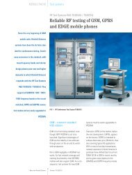
Articlespermit efficient and time-saving developmentof test software.TETRA protocol testerIn addition to measurement of RF characteristics,TBR35 prescribes protocolmeasurements, for which the TETRAprotocol tester is intended. Test casesare currently being created by ETSIusing the TTCN (tree and tabular combinednotation) specifying languageand are expected to be ready this year.The TETRA protocol tester consists of theTETRA signalling unit and the controlunit (FIG 3). The signalling unit comprisesthe RF frontend, A/D and D/Aconverters, TETRA filter and DSP cards.Network LayerNWKLogical LinkControl LayerLLCMedium AccessControl LayerMACPhysical LayerPHLPCOPCOPOFIG 4 TETRA layer model (PO = point of observation,PCO = point of control and observation)to an event that is to be triggered.Further menus can be selected tochange the basic configuration andother settings.The TETRA protocol tester not only checksthe response of a DUT to a standardprotocol, it also investigates DUT behaviourin the case of faults and deviations.The tester supports these investigationsby using predefined error typesin all protocol layers, which can beactivated by the user as required.The user may integrate his own proceduresthrough the PCOs for executinguser-defined tests and test cases asdescribed in TBR35. The same methodis used to implement the test casesformulated in TTCN. If the user does notwish TTCN formulation for test cases,he can formulate them direct in Cinstead. <strong>Rohde</strong> & <strong>Schwarz</strong> can supplyall protocol test cases to TBR35 asready implemented and installed turnkeysolutions.Dr. Hans-Jürgen Schneider;Wilfried TiwaldTETRAsignalling unitRFDUTTETRAcontrol unitFIG 3Functional units of TETRA protocol testerThe complete TETRA protocol stack isimplemented on the digital signalprocessors. User interface, TTCN tools(TTCN compiler, target-code generator)and test cases are provided in the controlunit. The TETRA signalling unit andthe control unit communicate throughPCOs (points of control and observation)provided between the individualprotocol layers (FIG 4).The protocol tester as the user sees it isa true representation of the TETRA layermodel. A separate window can beopened for each PCO between thelayers, in which the uplink and downlinkmessages are displayed. With theaid of predefined filters, informationitems of particular interest can be selectedand displayed, eg elementsviolating the protocol or correspondingFeatures of TETRA Test Systems TS8940TETRA simulatorGraphic user interfaceRF tests executable to TBR35Comprehensive system selftestPath compensation for increasedmeasurement accuracySimple creation and implementationof user-defined testsReader service card 153/01TETRA protocol testerGraphic user interfaceComplete implementation of TETRAprotocol stackTTCN test cases executable to TBR35All protocol layers software-implementedEasy implementation of user-definedTETRA protocol layersPredefined error simulation6 News from <strong>Rohde</strong> & <strong>Schwarz</strong> Number 153 (1997/I)
ArticlesTo accommodate the power sensor in asmall enclosure, a new solution had tobe found for the RF coupling circuit,which used to occupy as much as 80%of available space. As a result, a directionalcoupler of highest precision wasdesigned taking up no more than aquarter of the total volume of the powersensor. Up to a frequency of 3 GHz, directivity,which is the quantity relevantfor matching measurements, is greaterthan 30 dB and insertion loss is maximally0.09 dB, ie negligible. The twomeasurement channels are unsymmetrical,the reverse channel being 10 dBmore sensitive. This allows matchingmeasurements at very low power. Thesurfaces of the primary circuit are silverplatedthroughout, yielding excellentintermodulation characteristics, withunwanted frequency components keptto a minimum (FIG 3). Digital datastreams on the connecting cable gounnoticed by the user of course, andradiated emission from the microprocessorpresent at the RF connectorsis below the limit of detection. All thesefeatures make NRT-Z44 suitable notonly for testing but also for fixed installation.+43 dBm< -110 dBmdBm-120-140IMP 3Center 910 MHz1 kHz/divFIG 3 Sensor NRT-Z44 features excellent intermodulationcharacteristics: 3rd-order intermodulationproducts are well below –110 dBm. Carrierspacing (IMP3) is better than 155 dBc. Testparameters: 2 x 20 W (+43 dBm) carrier powerin GSM bandPower0PEPPEPCF=AVGBRST.AVAVGTimeFIG 4 Definition of key power parameters formodulated RF burst (AVG: average power, PEP:peak envelope power, BRST.AV: burst average,CF: crest factor)ly high accuracy. In measurement of thepower of a carrier with an unmodulatedenvelope (CW, FM, ϕM, FSK,GMSK, etc), uncertainty is no morethan 4%, taking into account the testfrequency. This performance is comparableto that of thermal power meters.Likewise, measurements on modulatedenvelopes (AM, π/4-DQPSK, CDMA,DAB) or superimposed carriers (eg ona common antenna feeder) will notproduce any significant errors up to anaverage power of 120 W.Directional Power Sensor NRT-Z44measures several parameters ofmodulated RF (FIG 4): peak envelopepower (PEP) provides information onthe periodic peak value of outputpower and is thus an important quantityfor describing the maximum outputlevel of a transmitter. The same appliesto the crest factor (CF), which is theratio of PEP to average power and directlyindicates substantial modulationdistortion. With a suitable evaluationbandwidth (selectable in steps), bothfunctions can be used for spread-spectrumsignals up to a bandwidth of2 MHz (CDMA, DAB) and yield satisfactoryresults much faster than expensiveenvelope analyzers.The power of RF bursts can be measuredin two ways: with the PEP functionfor bursts with an unmodulated envelopefrom 200 ns pulse width and withthe average burst measurement function(BRST.AV). The latter measures thepower of modulated bursts from theaverage power (AVG) and the dutycycle, which may be defined by enter-The key parameters measured byNRT-Z44 are average forward powerand load matching, both with extremeingthe burst duration and repetitionrate or determined automatically by thepower sensor. Stochastic modulationsignals can be described by means ofthe complementary cumulative distributionfunction (CCDF). This functionmeasures the probability of the envelopepower exceeding a selectablethreshold and thus allows determinationof amplitude distribution.Operation made easyOperation is easiest using the basicNRT unit. NRT has all the facilities thatthe user could possibly wish for.Besides a large display and a manageablenumber of clearly laid out keys,NRT offers remote control capability:via an IEC/IEEE bus in accordancewith IEEE 488.2 or via an RS-232 interfaceusing the SCPI instruction set, bothimplemented to standard. In manualoperation switchover between themain functions is made by a keystroke,eg changing units from W to dBm,switching between average power anda configurable envelope parameter(PEP, CF, BRST.AVG, CCDF) or betweenSWR and another matching parameter.Further functions selectable at a keystrokeinclude measurement of relativepower differences in dB or %, displayof maximum and minimum values, scalingof the two bargraphs, acousticSWR monitoring, switchover betweenforward power and absorbed power,and many more. Settings are made inthree clear-cut menus. Measurementaccuracy can be further enhanced byzeroing, frequency-response correctionand by selecting a source or load referenceplane.NRT can be extended with threeoptions. NRT-B1 allows all NAP sensorsto be connected. NRT-B2 providestwo additional connectors for typeNRT-Z sensors, switchover between thesensors being made in a matter of seconds.Option NRT-B3 turns NRT into amobile unit: an Ni-MH battery enablesup to eight hours continuous operationindependent of the AC supply. The batterycan be quick-charged within two8 News from <strong>Rohde</strong> & <strong>Schwarz</strong> Number 153 (1997/I)
Articlestional coupler, two power sensors anda peak power analyzer. The standalonesolution is therefore ideal forthe following applications: computercontrolledpower measurements in researchand development, power monitoringof transmitters and EMC testsystems, in-production measurementsand many more.All in all, NRT is a truly plug-and-playinstrument.Thomas Reichelhours by a built-in charger. Alternatively,a standby battery can be installedin next to no time. NRT together with allits accessories can be accommodatedin a sturdy carrier bag – ideal foron-site applications (FIG 5).FIG 5Power Reflection MeterNRT and 4-GHzDirectional PowerSensor NRT-Z44:competent tools foron-site applications,here during installationof mobile-radiobase stationPhoto 42 667/1combination affords full functionalityof Sensor NRT-Z44 at an unbeatableprice. The attractiveness of the newsolution becomes particularly evidentwhen it is compared to a conventionaltest setup consisting of a dual direc-REFERENCES[1] <strong>Rohde</strong> & <strong>Schwarz</strong> Catalog: Test & MeasurementProducts 96/97[2] Reichel, T.: Peak Power Sensors NRV-Z,NAS-Z, NAP-Z – PEP measurements onTDMA radios, TV transmitters and lots more.News from <strong>Rohde</strong> & <strong>Schwarz</strong> (1994)No. 145, pp 14 –17[3] Reichel, T.: Shortwave power heads for PowerReflection Meter NAP. News from <strong>Rohde</strong> &<strong>Schwarz</strong> (1987) No. 117, pp 39– 40What more can be said about NRT?It offers all the features expected of astate-of-the-art measuring instrument:continuous AC supply range withoutswitching, storage of instrument settings,no maintenance as no lithiumbuffer battery is used, firmware downloadvia the RS-232 interface, elapsedtimemeter, etc.Direct power monitoring on PCThe functionality of Directional PowerSensor NRT-Z44 can also be utilized tothe full without the basic NRT unit byoperating the sensor on the RS-232interface of a PC or other computer. Forthis, Interface Adapter NRT-Z3 (RS-232to RS-422) is required, which includesa direct plug-in power supply (seeFIG 1). Demo software is availablethat runs under Windows. The aboveCondensed data of Power Reflection Meter NRTBasic unit NRTFrequency rangePower measurement rangeMeasurement functions (sensor-dependent)PowerMatchingSensorsRemote controlPower supplyDirectional Power Sensor NRT-Z44Frequency rangePower measurement rangeDirectivityMeasurement functionsInterface with basic unit/computerReader service card 153/02200 kHz to 4 GHz1 mW to 2 kWaverage, peak envelope (PEP), burstaverage, complementary cumulativedistribution functionSWR, return loss, reflection coefficient,reverse powerNRT-Z44 and all NAP sensorsIEC/IEEE bus, RS-232AC supply and rechargeable battery200 MHz to 4 GHz0.03 to 120 W (AVG) / 300 W (CW, PEP)30 dB up to 3 GHzsame as basic unit NRTfull-duplex RS-422, power supply 7 to28 V DC; connection to RS-232 interfaceswith Interface Adapter NRT-Z3News from <strong>Rohde</strong> & <strong>Schwarz</strong>Number 153 (1997/I)9
ArticlesPortable Industrial Controller PSPMeasurement and controlmade mobileDownsizing in three attributes is what makes Industrial Controller PSP differentfrom its predecessors: down in price due to consistent design to cost, down insize making PSP <strong>Rohde</strong> & <strong>Schwarz</strong>’s first portable controller, and RF emission cutdown to a minimum.• two serial interfaces with FiFo,• fast 16-bit GPIB interface, compatiblewith IEEE-488.2 standard,• 3.5-inch disk drive,• integrated keyboard with 31 keysand knob.Despite its compact size, PSP has fourextension slots, two of which are fulllength (330 mm) and two just 18 mmshorter. This enables PSP to be adaptedto any special measurement task onhand.FIG 1Convenient useof Portable IndustrialController PSP inhelicopterPhoto 42 681HardwareThe excellent electromagnetic compatibilityof T&M controller PSP has notcome out of the blue. EMC criteria wereobserved throughout development anddesign of this controller. Extensive filteringon electronic components togetherwith a sealed casing and new style ofconstruction allow this industrial controllerto be used side by side even withhighly sensitive receivers without impairingresults. Two models are available:PSP2 without display and PSP7 with ahigh-contrast 8.5-inch display (FIG 1).What goes on inside PSP is just asgood, as its configuration shows:• AMD586 processor with 133-MHzclock,• 8 - Mbyte RAM, expandable to128 Mbytes,• 500-Mbyte harddisk on local bus,• fast, flickerfree SVGA graphics withup to 1280 x 1024 pixels resolutionon local bus for external monitors,• simultaneous display on internal(PSP7) and external monitor,• type-III PCMCIA interface,• parallel interface to EPP/ECP standard,PSP can be operated on batteries orDC sources, so it is not dependent onan AC supply. Its power supply unit acceptsthe kind of DC voltages availableon ships, in aircraft and vehicles. Internalor external batteries ensure severalhours of operation totally independentof stationary supplies. High operatingdependability and reliability (eg uninterruptiblepower supply, manufacture toISO 9000) guarantee problemfreeoperation, especially in automated production,where the controller can takeon central importance as a control andmonitoring element.10 News from <strong>Rohde</strong> & <strong>Schwarz</strong> Number 153 (1997/I)
ArticlesHF Transceivers XK2500 and XK2900The new members ofHF Transceiver Family XK2000New transceivers for 500 W and 1 kW output have been added to <strong>Rohde</strong> &<strong>Schwarz</strong>’s XK2000 family of radio equipment for shortwave communicationsfrom 1.5 to 30 MHz. Their range of applications covers land-mobile and shipboarduse as well as stationary operation by authorities, national forces, securityservices and the like.used (L or R). The man/machine oruser interface of the 500-W and 1-kWtransceivers is the same as that ofthe smaller XK2100 with output powerof 150 W [2]. Power amplifiers andreceiver/exciter may be spaced up to65 m apart. The interface between receiver/exciterand amplifier handlesvaried chores such as digital controllingand analog regulation of power amplifiers,controlling of antenna tuningunits, line matching unit, harmonicsfilter and antenna. This guarantees full1-kW HF Transceiver XK2900 consisting ofreceiver/exciter, 1-kW power amplifier andpower supply unit Photo 42 700Nowadays worldwide shortwave communicationmeans automatic, fast andindependent radio links for speech anddata transmission which connect twoterminals direct over any distance. Prerequisitesare reliable call setup, fastand secure data transmission andadaptive response of the system toany link disturbance. Thanks to highlyadvanced radio processors, perfectdata protection and high-speed datamodems, <strong>Rohde</strong> & <strong>Schwarz</strong> hardwareand firmware fully meet these requirements.In addition, a fast serial bussystem as well as digital processing ofboth transmit and receive signals guaranteeexcellent performance in <strong>Rohde</strong>& <strong>Schwarz</strong> transceivers. Operatingcosts are very low, so the user gets anexceptionally economical solution forworldwide speech, data and imagetransmission [1].The new members of the XK2000family, HF Transceivers XK2500 andXK2900 (FIG), were developed to themost highly advanced standards andare produced using the very latest processes.They may be controlled locallyor remotely depending on the versionof Receiver/Exciter GX2900 that iscompatibility of XK2500 and XK2900with ready installed ATUs or antennasof the HF850 family. Furthermore, aplug-in module allows control of anactive selective antenna for duplexoperation with a separate receive antennaor of a motor-tuned preselectorfor operation under extreme collocationconditions.All options of Transceiver XK2100can naturally also be accommodatedin Receiver/Exciter GX2900, forexample:• automatic phone patch for telephoningon shortwave,• communication processor for automaticlink setup,12 News from <strong>Rohde</strong> & <strong>Schwarz</strong> Number 153 (1997/I)
ArticlesTV Test Transmitter SFQDigital test signalsfor the television futureTV Test Transmitter SFQ is a complete solution for testing digital TV receivers. Itspecializes in the generation of standard DVB signals for satellite and cable transmissions.SFQ also processes analog, frequency-modulated satellite TV and soundsignals to PAL, SECAM and NTSC standards. Audio signals are transmitted withanalog FM and digital ADR sound subcarriers.• up to twelve ADR sound subcarriers(Astra digital radio) with internalMUSICAM generators,• internal noise generator.These features open up a wide field ofapplication for SFQ in developmentand production as well as in the serviceof digital TV receivers and their modules.System margins have to bechecked at the latest during final testingof receivers to avoid their early failureat the customer. SFQ with built-in noisegenerator and MPEG2 Generator DVG[2] are the right team for this job. Inthe laboratory SFQ convinces by itsgreat variety of modulation modes andparameter settings. When it comes toEMC testing, SFQ and DVG form anideal signal source for checking out TVreceivers.Design and optionsFIG 1 TV Test Transmitter SFQ generates standardDVB signals. Photo 42 592Timed just right for the beginning of theera of digital TV, <strong>Rohde</strong> & <strong>Schwarz</strong>is launching a new TV test transmitteron the market: the SFQ (FIG 1). It iscapable of processing source-codedsignals to MPEG2 standard for digitaltransmission via satellite or cable. Themain features of SFQ are:• wide output frequency range from0.3 to 3300 MHz,• generation of standard DVB-S andDVB-C signals (S = satellite, C =cable) in line with ETS 300 421 and300 429 specifications [1],• input data rate selectable between 2and 60 Mbit/s,• switch-selected energy dispersal,Reed-Solomon coder and interleaver,• variable rolloff factor for pulse shaping,• data, random sequence, null transportstream packet selectable asmodulation signal,• application of external I/Q signals,• adjustable puncturing rate for QPSK(quadrature phase shift keying),• selectable QAM (quadrature amplitudemodulation) modes (16, 32,64, 128, 256QAM),• generation of standardized FM satellitesignals,• selectable standard for FM transmission(PAL, SECAM and NTSC),• up to six FM sound subcarriers withinternal audio generators,The flexible modular concept allowsSFQ to be equipped to suit thecustomer’s measurement requirements.The TV test transmitter comes in threemodels (FIG 2). Model 10 is particularlysuitable for the requirements ofDVB applications. Model 90 comprisesall the modules required for analogsatellite FM transmission. Model 50is the complete solution made up ofmodels 10 and 90 for generatingdigital DVB signals and analog FMsatellite signals.Realistic receiving conditions can besimulated with the aid of a noise generator.For this purpose the digital SFQmodel 10 can be equipped with abroadband FM module comprising anoise generator in addition to the FMmodulator. The noise signal is addedto the information signal by way ofa coupler to produce a defined C/N(carrier-to-noise) signal. With the broadbandFM module included in models90 and 50, the noise generator is automaticallyavailable. The FM subcarriermodule in models 90 and 50 generatestwo completely conditioned FMsubcarriers. Two additional subcarriermodules may optionally be fitted: FM or14 News from <strong>Rohde</strong> & <strong>Schwarz</strong> Number 153 (1997/I)
Articlesa) b) c) d)FIG 4 Constellation diagram showing at leftideal 64QAM signal of accurately alignedI/Q modulator a) and deliberately misaligned64QAM signals with b) 10% amplitude imbalance,c) 10° phase error and d) superimposednoise (C/N = 24 dB)(FIG 4). DVB Test Receiver EFA [5] isan ideal instrument for detecting andcalculating QAM quality parameters.Analog baseband conditioningand frequency modulationAnalog FM TV transmission via satellitewill certainly be used for years alongsidedigital QPSK modulation. For thisreason SFQ is also able to conditionanalog TV channels with all appropriatecharacteristics: eg dispersal signalsynchronous to video frame, automaticdeviation doubling in the case of videosignal failure, deviation inversion forvideo and energy-dispersal signal,deviation adjustment for video signal,dispersal signal and separately foreach sound subcarrier. TV standardsPAL, SECAM or NTSC are selectable.In the Astra satellite system it is plannedto transmit further audio and data channelsin addition to the accompanyingstereo (7.02/7.20 MHz) or mono(6.5 MHz) sound channel. The built-inMUSICAM generator can produce upto twelve ADR subcarriers. If more thansix subcarriers are required, a secondSFQ will have to be used. The modulesof this unit are controlled by the masterSFQ via the internal SERBUS. SFQ thusmeets all requirements for conditioninganalog TV channels transmitted viasatellite.Noise generatorThe noise generator produces whitenoise with a Gaussian distribution atthe set output frequency over the channelbandwidth. The power density ofthe noise signal can be set indirectly asa C/N (carrier-to-noise) ratio. This isextremely convenient for the user asthe C/N ratio in dB can be enteredimmediately after the selection of thedemodulator receive bandwidth. SFQcan thus simulate different types of interferenceas they really occur along thesatellite or cable transmission path tothe receiver.Erhard Kretschmer;Franz-Josef ZimmermannCondensed data of TV Test Transmitter SFQREFERENCES[1] ETS Specifications (1994): Digital broadcastingsystems for television, sound anddata services. Framing structure, channelcoding and modulation for 11/12 GHzsatellite services (ETS 300 421); ~ for cablesystems (ETS 300 429)[2] Fischbacher, M.; Weigold, H.: MPEG2Generator DVG and MPEG2 MeasurementDecoder DMVD – Test equipment for digitalTV in line with MPEG2. News from <strong>Rohde</strong> &<strong>Schwarz</strong> (1996) No. 152, pp 20–23[3] DVB-PI 154: Interfaces for CATV/SMATVHeadends and Similar Professional Equipment(1995)[4] DVB-TM 1601: Measurement Guidelines forDVB Systems[5] Balz, C.; Polz, E.; Fischer, W.: TV Test ReceiverFamily EFA – Top fit for digital television.News from <strong>Rohde</strong> & <strong>Schwarz</strong> (1996)No. 152, pp 17–19Coding and modulation (DVB-S and -C) to ETS 300 421 and ETS 300 429For DVB-SPuncturing rates 1/2, 2/3, 3/4, 5/6, 7/8ModulationQPSKFor DVB-CModulation16, 32, 64, 128, 256QAMI/Q modulationDetuning of phase error ±10°Detuning of amplitude imbalance ±10%Detuning of residual carrier 0 to 50%Analog baseband and FMVideo and dispersal signal conditioning for PAL, SECAM and NTSCFM sound subcarriersup to 6, internalADR sound subcarriersup to 12, internalOutput frequency range0.3 to 3300 MHzOutput level+4 to –99 dBm (CW: +13 dBm)Noise generatorC/N = 0 to 60 dB, resolution 0.1 dBReader service card 153/0516 News from <strong>Rohde</strong> & <strong>Schwarz</strong> Number 153 (1997/I)
Refresher topicDigital modulation and mobile radio (IV)3.1 π /4 differential QPSKA special form of baseband signalencoding that only uses phase shifts of45° and 135° is used for networks operatingto the Japanese JDC standardand for digital trunked-radio networksin Europe and this is one solution to theproblem. The approach at least preventscarrier extinction, momentary lossof the carrier. With π/4 differentialQPSK the information is not representedby an absolute phase but rather interms of a phase difference. So coherentdemodulation is unnecessary andthere is no need to deal with the difficultproblem of reconstructing a carrier withexactly the same frequency and phaseof the original from the received signal,strongly distorted by the mobile-radiochannel.TABLE 2DibitPhase transition00 ∆ϕ = 0 · π/2 + π/4 = 45°01 ∆ϕ = 1 · π/2 + π/4 = 3π/4 = 135°11 ∆ϕ = 2 · π/2 + π/4 = 5π/4 = 225° = –135°10 ∆ϕ = 3 · π/2 + π/4 = 7π/4 = 315° = –45°Phase transitions for π/4 DQPSK101101011101100110 Bit sequence12 21δ(t)δ(t)11-1 0 2 2 10 2 2 -112 2 2 22 2 110 1 1 0 δ c l(t)Q(t)2 2 12 2 12 2H(f) = sinxxSquare filter(no band limiting)δ l(t)c Q(t)c l(t)2986475 132 2 Filter with Nyquist edgeThe original data sequence a(n) undergoesserial/parallel conversion, thusgeneratinga new symbol sequenceb(m) ∈ {00; 01; 10; 11} whose elementsare assigned to the phase transitionslisted in TABLE 2. This assignment isessentially a type of Gray coding,adjacent symbols and signals differingby just one bit. An approach of thiskind reduces bit errors. The π/4 offsetgives the modulator a memory function.The phase transitions are modulatedonto the carrier by an I/Q modulatorFIG 9(band limiting)c Q(t)Data sequence, I/Q signals and phase state diagrams for π/4 DQPSK(FIG 8). First the current carrier phaseis obtained from the sequence of phasedifferences by means of a feedback loop,then the two modulation signals c I (t)and c Q (t) are calculated from the carrierphase. At this stage the modulation signalsare in the form of delta functionsδ(mT) ∈{+1; + 1 / 2 √ –– 2 l ; – 1 / 2 √ –– 2 l ; –1}.They are then band limited by passingthem through lowpasses (FIG 9). Araised cosine filter is used. Moreover,filtering is shared between the transmitterand the receiver.By splitting up the overall filter responseinto equal parts at the transmitter andreceiver end1 0 0 1SP1 00 1▲ϕkcos(2πft)TϕkH(f) = — 1– sin —————— (1– α)1 for 0 ≤ f ≤ ———— 2T———————————————1 π(2fT –1) (1– α) (1– α)for ————< f ≤ ———— (18)2 2α 2T 2T(1– α)0 for ————< f2Tδ l(t)PAMDAδ Q(t)PAMδ I/Q(t) {+1, +1/2 2, –1/2 2, –1}D-sin(2πft)AFIG 8I/Q modulatorfor π/4 DQPSKit is possible to obtain an optimalsignal/noise ratio when recovering thereceived symbol sequence b’(m).To be continued.Peter HatzoldNews from <strong>Rohde</strong> & <strong>Schwarz</strong>Number 153 (1997/I)17
Application notesIn-production testing of automotive electronicsThe kind of electronic components usedin automobiles are frequently subject toextreme conditions like large temperaturefluctuations and strong vibrations,besides being exposed to electromagneticinterference, so they have to meetparticularly stringent requirements toguarantee operational reliability andsafety. This means that, in addition topainstaking development and testingof such circuitry, thorough quality assuranceis also called for during production.It is not enough to simply checkproducts for manufacturing defects. Acombination of different test proceduresis necessary to comply with the highstandards imposed. In many casesfunctional tests and a run-in test aremade obligatory by automobile manufacturersanyway. On top of that all testresults have to be fully documented andarchived for a long period to satisfyproduct liability and ISO 9000 requirements.On the other hand, competitionis particularly fierce among suppliers tothe automobile industry, so cost cuttingin manufacture is essential. This in turnentails the necessity to employ cost-efficienttesting solutions and to optimizetest times. An example taken from industryillustrates how <strong>Rohde</strong> & <strong>Schwarz</strong>can contribute to producing the rightanswer.The Temic Microelectronic company inIngolstadt (Bavaria) produces centralcontrollers for the Daimler-Benz E seriesand SLK roadster. This module controlsvarious devices such as direction indicators,windshield wipers, windowopeners and sun-roofs. The module isabout the size of a dual Eurocard andconsists of numerous analog and digitalcomponents, one or two microprocessors,various power drivers and switch-FIG 1Test WorkstationTSAC in use atTemic Microelectronicin IngolstadtPhoto 42 627/218 News from <strong>Rohde</strong> & <strong>Schwarz</strong> Number 153 (1997/I)
Application notesing relays. The PCB is fitted with SMTcomponents on both sides and the endproductis housed in a plastic casing. Tocheck out these modules Temic usesaltogether five test systems from <strong>Rohde</strong>& <strong>Schwarz</strong> including programs and testfixtures (FIG 1).The test concept involves two phases:first a combinational test on a TestWorkstation TSAC [1] followed by finaltesting of the complete modules by aUniversal Test System TSU [2] (FIG 2).In the combinational test the module iscontacted by a vacuum fixture. Thanksto its double-chamber design, the fixtureallows increased throughput bytesting one module on one side of thefixture while another is being placed fortesting on the other. The TSAC systemfirst checks modules for manufacturingdefects in an analog in-circuit test, thencustomer-specific components are examinedin a functional test. Here themodule’s own diagnostic capabilitiesare utilized, via the CAN bus, whichmaintains communication between individualcontrol modules in a vehicle,and via the K bus, which is anotherserial line and serves for fault diagnosisin a vehicle. For such tasks all systemsof the TSA and TSU series can be fittedwith an application module allowingcustomer-specific solutions based on aCAN bus and a K bus interface to bemounted on available space free onthe module. All functional tests are performedwith the aid of load simulationunits integrated in the fixture. Oncethese have been completed the usercan be sure that a module is free ofmanufacturing defects and all its basicfunctions are in order.Upon completion of the combinationaltest, modules are sampled at randomfor reliability. The samples undergoan active run-in test of severaldays’ duration, performed by a TSUsystem with a special switching matrixand a climatic rack. During the entireprocedure the modules are suppliedwith operating voltage and cycledthrough functional tests at changingtemperatures.Combinational testwith Test WorkstationTSACRepairRun-in test withUniversal Test SystemTSUSamplesFinal test withUniversal TestSystem TSURepairFIG 2 Diagram illustrating test strategy usingTSAC and TSUOnce a module has finally beenhoused in its plastic casing, it undergoesfinal testing via its interface contacts.Real loads, eg electromotors, areused to make this as realistic as possible.The functions of the modules arefully tested step by step, which alsoinvolves use of the CAN bus and theK diagnostic line. Automatic alignmentis carried out simultaneously, but despitethe large number of individual testsand the alignment procedure, overalltime to test is only about 1 min 20 s.All related test data are saved accordingto ISO 9000 guidelines and thenarchived. For this purpose the testsystems convert the data to a suitableformat and transport them to the quality-managementsystem. Test data areused to draw up quality statistics andfacilitate paperless repair. Each testsystem is supplemented by repair stations.The fault data of a module can bedisplayed on a repair station’s screenby reading the EEPROM-stored serialnumber specific to the module andappropriate repair actions enteredsubsequently. This guarantees uninterrupteddocumentation of module servicelife right from the beginning.Both systems – TSAC and TSU – belongto the same test system family, so theuser will be able to considerably cutdown on times needed to develop programs,seeing as large parts of thefunctional tests contained in the combinationaltest, final test and active runintest are very similar and can be transferredfrom one system to another. Plus,the same modules can be used in bothsystems, which is another benefit as faras the CAN-bus interface is concerned.Combination of TSAC and TSU provesto be a particularly economical solutionfor this two-phase test strategy, as anoptimal test platform can be selectedfor each phase without the cost of unnecessaryoverheads.<strong>Rohde</strong> & <strong>Schwarz</strong> devised a turnkeysolution including the complete projectdevelopment, configuration and supplyof the test systems, test programs andfixtures as well as commissioning andthe training of Temic staff.Klaus KundingerREFERENCES[1] Tschimpke, L.: Test Workstation TSA for testingin electronics production and service.News from <strong>Rohde</strong> & <strong>Schwarz</strong> (1991)No. 132, pp 4– 7[2] Kundinger, K.; Tschimpke, L.: Universal TestSystem TSU – Versatile test platform forproduction and service of electronic modules.News from <strong>Rohde</strong> & <strong>Schwarz</strong> (1996)No. 150, pp 13–15Reader service card 153/06News from <strong>Rohde</strong> & <strong>Schwarz</strong>Number 153 (1997/I)19
Application notesMeasuring noise parameters of twoportswith Spectrum Analyzer FSMDetermining the noise parameters oftwoports requires measurement ofspectral noise-power density. Normallysuch measurements are carried outwith highly sensitive receivers by theradiometer principle or with commercial,automatic noise-factor meters.Lately spectrum analyzers too comeequipped for this application, althoughthey are mainly intended for observingspectra with discrete frequencies ratherthan precise measurement of extremelylow noise levels. Stability of receiverparameters with time is an importantcriterion for these measurements so thatcalibration should not be necessarymore than once a day.Spectrum Analyzers FSM from <strong>Rohde</strong>& <strong>Schwarz</strong> [1] are not just analyzersbut also highly stable test receiverssuitable for noise measurements upto 26.5 GHz, and in fact they offerclear advantages over commonly usednoise-factor meters. The advantagesare very evident when it comes to determiningtransistor noise parameters.This is far more complex than measurementson complete amplifiers ormixers in a 50-Ω system for example.Various impedances, which can showa lot of dependence on frequency,have to be applied to a transistorinput, so the variable receiver bandwidthof the spectrum analyzer isa great advantage. MESFETs andHEMTs exhibit extreme mismatch inthe lower GHz region and have highgain, so they are prone to oscillations.For this reason a spectrum analyzerwould be required in the setup anywayto detect the absence of oscillationsduring noise measurements.The Ferdinand Braun Institut fürHöchstfrequenztechnik (institute ofmicrowave engineering) in Berlinwas faced with the need to measureMESFETs in the frequency range 0.2to 2.7 GHz. But the required accuracycould not be achieved with commercialnoise test systems using commonreceivers. FSM with its selectablereceiver bandwidth in conjunctionwith a special impedance tunershowed itself as a dependable solutionfor measuring the required parameters.Complete noisecharacterizationThe noise figure of a twoport dependson the circuitry at the input. The minimumnoise figure F min can only beobtained with noise matching, iewhen the optimum source reflectioncoefficient Γ opt is effective at the input.The relationship between noise figureF and source reflection coefficient Γ Sis defined by the following formula:4R n Γ S – Γ opt 2F= F min + ––––– ––––––––––––––––––––––––Z L 1– Γ S 2 1+ Γ opt 2Γ S is the source reflection coefficient,Z L the reference impedance and R nthe noise resistance. The latter is ameasure of deterioration of devicenoise parameters as you move awayfrom optimum source reflection coefficient.The above formula shows that fourparameters are needed to determinethe complete noise characteristic of anetwork at a particular frequency: minimumnoise figure F min , noise resistanceR n , optimum source reflection coefficient|Γ opt | and the phase angle ofΓ opt . These four parameters are normallydeduced by connecting a circuit tothe input that has been determinedbeforehand in a reflection coefficientmeasurement and by measuring thenoise power at the output. The bestknown method is that of Lane [2]. It isbased on noise-figure measurement fordifferent source reflection coefficientsand subsequent matching to the straightpart of the characteristic as defined bythe formula above. Since four unknownquantities are to be determined, at leastfour measurements are required. But agreater number of measurements (25 inthis case) is normally performed to increaseaccuracy. The various source reflectioncoefficients are in most casesobtained with low-loss impedance tuners,preferably under computer control,connected between the noise sourceand the DUT. In the Y method thenoise figure is determined by alternatemeasurements with the noise sourceswitched on and off. But there are twoshortcomings that cause problems particularlyin measurement of low-noisetransistors (MESFETs, HEMTs) in thelower GHz region. Firstly, the sourceadmittance is different in the on andoff state and, secondly, tuner loss (1 to2 dB) is usually higher than the noisefigure of the DUT (0.1 to 0.5 dB),besides being different from setting tosetting.For these reasons other types of testsetup are increasingly being used. Thecold-source method [3] means measuringfor at least five different sourcereflection coefficients, just one of themwith increased noise temperature. Theothers are formed by the inherentnoise of tuner losses at ambienttemperature. The cold connections areimplemented by mechanical or PINdiodeswitches for instance, the hotconnection by a noise generator. Thismethod eliminates the two error sourcesmentioned above. However, it doesinvolve permanent use of a vectornetwork analyzer, because the s-parametersof the DUT, tuner system andreceiver have to be known. A simplerway is the standard 8-term model [4].In addition to the four noise parameters,the input admittance of theDUT is also determined. So once a20 News from <strong>Rohde</strong> & <strong>Schwarz</strong> Number 153 (1997/I)
Application notesController• The selectable input bandwidthpermits measurement with strongnarrowband transformation at thetransistor input.DC feedDC feedNoisegeneratorSwitchDUTVectornetworkanalyzerSwitchSpectrumanalyzerPowersupplyPowermeterFIG 1Block diagramof test setup fornoise measurementswith SpectrumAnalyzer FSM• A spectrum analyzer is required inany case to monitor the oscillationstatus.• All settings, switching of the 28 Vfor the noise generator and datareadout can be performed on anIEC/IEEE bus.tuner with reproducible settings ischaracterized, the cold method allowsreceiver and DUT parametersto be characterized, ie all requiredparameters to be determined.Special features of transistornoise measurementsWhile only one measurement is requiredfor routine measurements onamplifiers or mixers in a 50-Ω system,ie Γ opt and R n are not determined at all,transistors make much higher demandsfor the following reasons:1. The minimum noise figure of MES-FETs and HEMTs in the lower GHzregion is very small (F min 0.5 dB).2. The input impedance is almost purelycapacitive, so noise matching forthe source reflection coefficient|Γ opt| occurs at approx. 1. This isdifficult to achieve with an impedancetuner.3. The very high gain resulting fromstrong transformation at the inputmay cause a transistor to oscillate(> 20 dB).4. Strong transformation is of narrowbandwidth, meaning that doublesidebandmeasurements are notpossible because Γ S is different inthe two sidebands, even if they areonly a few MHz apart. In the lowerGHz region the bandwidth has tobe limited for single-sideband measurementtoo. This is not possible withnoise-factor meters, which usuallyhave a bandwidth of 4 MHz.Here, by contrast, the decisive advantagesof FSM as a noise-factor meter:• High sensitivity in conjunction with alow-noise preamplifier ensures lownoise figure in the receiving system.The wide FSM frequency range(100 Hz to 26.5 GHz) is only limitedby this preamplifier.• Single-sideband reception meansthat no tunable microwave filtersare required.FIG 2On-wafer test setupfor noise measurementswith SpectrumAnalyzer FSMat Ferdinand BraunInstitut fürHöchstfrequenztechnik,BerlinPhoto: BlaskA practical noisemeasurement systemFIG 1 shows the test setup with acontroller. Spectrum Analyzer FSM isused as a power meter with frequencyconversion. The measured level canbe read in the display with a marker orindicated on a highly sensitive powermeter connected to the IF output(21.4 MHz). The latter solution wasused at the Ferdinand Braun institutebecause the linearity of the marker displayis not sufficient for all purposesand measured values would have to belinearized with the aid of a correctionfunction. However, very good resultswere obtained with the power meter.The broadband amplifier (0.1 to 4 GHz)connected ahead reduces the noiseNews from <strong>Rohde</strong> & <strong>Schwarz</strong>Number 153 (1997/I)21
Application notesfigure of the receiver system to F < 2 dB.The DUT is connected between animpedance transformer and the broadbandamplifier. This DUT may be eithera single transistor in a test fixturewith coaxial connectors or an on-wafertransistor contacted by microwavetest probes (FIG 2). The impedancetransformer consists of a step attenuator(switchable between 0 and 11 dB) andan electromechanical SP12T switch,the outputs of which are alternatelyopen or shorted. Because the linelength varies with the switch position,the phase angle of the reflection coefficientis different at each frequency.The magnitude can be varied in additionusing the attenuator, and a 50-Ωsystem can be implemented in the11-dB setting. Thus a great variety ofsource reflection coefficients is obtained.Although these are arbitraryvalues, they may be employed for evaluationby the Lane method.The following system parameters mustbe known for fully determining thenoise parameters of a transistor atdifferent frequencies:• The four noise parameters of thereceiver referred to the input. Inthis case the microwave probe atthe transistor output is used as thereference plane. The test receivertherefore comprises the microwaveprobe, DC feed, switch, preamplifierand FSM as well as the connectingcables, which should be asshort as possible and of low loss.For measuring these parameters theimpedance tuner is connected tothe input via a thru, all tuner settingsare selected and the receiver ismeasured in the same way as theDUT subsequently. Using these datathe contribution of the receiver canbe corrected when noise measurementson the transistor are performed.• The reflection coefficients of the followingcomponents:a) receiver with respect to the inputreference plane,b) noise generator at the same referenceplane,c) impedance tuner at the referenceplane of the input microwave probe.The impedance tuner therefore includesa DC feed and the requiredconnecting cables in addition to theSP12T switch and the attenuator.Particular care should again betaken that low-loss componentsare used so that areas around theouter edges of the Smith chart canbe reached for approaching theΓ opt of the field-effect transistors.For interpretation of noise measurements,the twoport s-parameters ofthe DUT also have to be known tocalculate mismatch at the receiver3.185.353.175.274.843.12.644.011.51.592.561.712.233.231.521.271.021.11.151.181.491.72FIG 4 Distribution of reflection coefficients ofimpedance network at various attenuations (f =700 MHz). Noise figures measured with teststructure in FIG 3 are marked. Distribution of reflectioncoefficients is different for each frequencyand therefore random but exactly reproducible.input and the noise power deliveredfrom the tuner to the DUT [5]. Noiseparameters are determined mostlyat discrete frequencies in a specificfrequency band. The required s-parametersare previously measuredand stored. When measurements arerepeated at the same frequencies andthe test setup is not changed, calibrationof the bandwidth-gain product isseldom required.6 Ω 18 Ω0.57 pFFIG 3 Noise test structure in MMIC technology.Bright meander lines are ohmic resistors. MIMcapacitance to ground can be seen in upper leftthird. Four noise parameters can be calculatedaccurately from equivalent T circuit.• The bandwidth-gain product ofthe receiving system is measuredwith the calibrated noise generatorconnected to the input. For this,the attenuation between the coaxialnoise generator and the referenceplane at the receiver inputhas to be known accurately and isdetermined in a twoport measurement.Measurement examplesIn a trial of the test setup, measurementswere carried out on enclosedMESFETs, HEMTs in a coaxial testfixture [6] and on-wafer MESFETsproduced at the Ferdinand Brauninstitute. The following settings weremade on FSM for the on-wafer meas-22 News from <strong>Rohde</strong> & <strong>Schwarz</strong> Number 153 (1997/I)
Application notesurements used to demonstrate the test procedure:Mode Resol. BW Video BW RF attenuation Ref. level Span Sweep ScaleAnalyzer 1 MHz 30 kHz 0 dB –20 dBm 0 Hz 100 ms logA “noise standard” with parametersreproducible by the test setup would bedesirable for assessing system accuracy.Ideally a standard of this kind wouldbe a transistor with accurately known s-and noise parameters. This cannot beobtained with an on-wafer device andwith conventional test equipment becauseof the problems described withnoise measurements in the frequencyrange 0.2 to 2.7 GHz. Furthermore,the accuracy of factory calibration ofthe noise generator (max. inaccuracy0.3 dB) is not sufficient to measure transistorswith F min from 0.1 to 0.5 dB. Forthis reason a purely passive test structurewas produced on the wafer togetherwith the transistors (FIG 3), thefour noise parameters of which aresimilar to those of the MESFET – withoutgain of course – and which can beextracted from the s-parameters, whichcan be measured with high accuracy.The measurement should not only confirmthese four parameters but alsoyield the corresponding noise figure foreach of the source reflection coefficients.The deviation of each testpointfrom the theoretical value according tothe equation is an indicator of measurementquality and thus of the performanceof the test setup. Calibration ofthe noise generator can also bechecked. The Smith chart in FIG 4shows the source reflection coefficientsobtained at different switch settings ofthe impedance tuner together with themeasured noise figure of the test structure.The theoretical characteristic andmeasurement results are compared inFIG 5: even at a great distance from thenoise minimum, no deviation can befound between the two sets of values.This is a measure of the high accuracyof the test setup based on SpectrumAnalyzer FSM.This high accuracy is also confirmed intransistor measurements. But the evaluationmethod has to be modified thistime because of the extremely low noisefigures and high gain. According to theequation the minimum noise figure isobtained by intercepting the ordinateNoise figure F (lin)FIG 5 Lane diagram of noise figure versus deviationfrom noise minimum x = |Γ S –Γ opt | 2 /(1–|Γ S | 2 )|1+Γ opt | 2 . Intercept on ordinate isgiven by F min , slope of noise resistance by R n .Examples for measurement at 700 MHz. Bluestraight line represents calculated values of teststructure.Noise figure Fm25dB201510500.5dB0.40.30.20.10Noise test structurew = 80 µmMESFET0 0.5 1 1.5 2 2.5Deviation from noise minimum xw = 160 µm0 0.5 1 1.5 2 2.5 GHz 3FrequencyFIG 6 Minimum noise figure versus frequency.Two MESFETs with gate widths of 80 and 160 µm.Operating point: V = 3 V, I = 10 mA. Determinationaccording to [7].for Γ S = Γ opt . However, with noise figuresaround 0.1 dB this value cannotbe determined accurately as Γ opt canvery seldom be directly set. For this reasonthe method used in this case isbased on evaluation of noise resistanceR n [7]. R n is determined by the slope ofthe equation and can therefore be readmore exactly than the intercept on theaxis. The method uses a theoreticalnoise model for field-effect transistorsand yields simple formulae in the lowerGHz region, thus permitting this kind ofevaluation. Above about 5 GHz theseconditions are not fulfilled, but since thenoise figure of transistors is higher andΓ opt < 1, this method is no longer required.FIG 6 shows a MESFET measurementin the frequency range 0.2 to2.7 GHz.Dr. Peter Heymann (Ferdinand BraunInstitut für Höchstfrequenztechnik, Berlin);Dr. Wojciech Wiatr (Warsaw technicaluniversity, institute of electronicfundamentals)REFERENCES[1] Evers, C.: 100 Hz to 26.5 GHz: new level ofperformance for microwave region withSpectrum Analyzer FSM. News from <strong>Rohde</strong>& <strong>Schwarz</strong> (1991) No. 133, pp 4–7[2] Lane, R.Q.: The Determination of DeviceNoise Parameters. Proc. IEEE Vol. 57(1969), pp 1461–1464[3] Adamian, V.; Uhlir, A.: Simplified NoiseEvaluation of Microwave Receivers. Trans.IEEE Vol. IM-33 (1984), pp 136 –140[4] Wiatr, W.: Characterization of RadiometerUsing Eight-Term Linear Model. Trans. IEEEVol. IM-44, No. 2 (1995), pp 343–346[5] Meierer, R.; Tsironis, C.: An On-Wafer NoiseParameter Measurement Technique withAutomatic Receiver Calibration. MicrowaveJournal Vol. 38 (1995) No. 3, pp 22–37[6] Heymann, P.; Wiatr, W.: A Universal Systemfor Measuring Two-Port Noise Parameters.Proc. XI MIKON 96, Warsaw 1996[7] Prinzler, H.; Heymann, P.: Intrinsic NoiseSources of GaAs Field Effect Transistors:Theory and Experiment in the 10 MHz –12 GHz Frequency Range. Frequenz Vol. 46(1992), pp 53–59Reader service card 153/07 for further informationon FSMNews from <strong>Rohde</strong> & <strong>Schwarz</strong>Number 153 (1997/I)23
Application notesFit for future radiomonitoring and radiolocationup to 3 GHzContinuous growth in wireless communicationmeans that the capacity ofclassic VHF and UHF bands can nolonger ensure interference-free radiotraffic. So more and more operators allover the world are moving into higherfrequency bands through to 3 GHz.<strong>Rohde</strong> & <strong>Schwarz</strong> is keeping pace withthis trend by introducing frequencyextensionoptions for Compact ReceiverESMC and Digital Monitoring DirectionFinders DDF0xM.Thanks to the variety of tuners available(model 0: 500 kHz to 30 MHz, model1: 20 to 650 MHz, model 2: 650 toROHDE & SCHWARZIFFE, 21.4 MHzLO1, 1170 to 1820 MHzLO2, 1100 MHzRef. 10 MHzSerial controllatest radio services in frequency bandsup to 3 GHz, eg GSM, PCN, PCS, WLLand GPS. It can be housed in a 19-inchrack together with ESMC or otherwiseused as a detached unit (FIG 2). Allentries and displays are effected onthe ESMC front panel or on its remotecontrolinterface, so all ESMC functionsROHDE & SCHWARZFIG 2 Variouscable sets permitdetached use offrequency-extensionunit up to 10 m away.advantages of the teamed equipmentare its compact design for mobileuse, the possibility of both manual andremote control in semi-automatic applications,and the variety of interfaces forstationary missions. So the user canchoose a solution tailored to his specificrequirements and for optimumprice/performance.Of course, <strong>Rohde</strong> & <strong>Schwarz</strong> alsohas suitable antennas to offer for theextended frequency range – for omnidirectionalreception of vertically andhorizontally polarized waves, plus logperiodicantennas for directional reception.ESMC and ESMC-FE together withdigital VHF-UHF Direction FinderDDF190 [2] form a powerful andattractively priced, compact system thatis ideal for mobile radiomonitoring andradiolocation up to 3 GHz (FIG 3).FIG 1 Frequency Extension ESMC-FE (right)takes range of ESMC monitoring receiver throughto 3 GHz. Photo 42 4691300 MHz), the modular VHF-UHFCompact Receiver ESMC [1] forms thebasis of many monitoring systems.Frequency Extension ESMC-FE (FIG 1)offers capability for monitoring theare also available to Frequency ExtensionESMC-FE. Options enable coverageof a continuous receive range from500 kHz through 3 GHz.Due to the many possible combinationsand a future-oriented concept in termsof options (preselection for tuner 0,antenna splitter, OCXO reference)ESMC with ESMC-FE covers the wholespectrum of radiomonitoring tasks. TheDepending on the DF converter used,Digital Monitoring Direction FindersDDF0xM cover the frequency range0.3 to 30 MHz, 20 to 1300 MHz or0.3 to 1300 MHz [3]. UHF DF ConverterET070 and UHF DF AntennaADD070 are available for extensionto the frequency range 1300 through3000 MHz. Control is always handledfrom VHF-UHF DF Converter ET050of the basic model, so subsequent extensionis simple even when tuners areused in a detached role (FIG 4). Thecontrol and signal-processing softwarerequired for the frequency extensionis already in place in the basic model.24 News from <strong>Rohde</strong> & <strong>Schwarz</strong> Number 153 (1997/I)
Application notesFIG 3 Compact radiomonitoringand radiolocation system in mobileDF unit: VHF-UHF Receiver ESMCwith Frequency Extension ESMC-FE,Panoramic Display EPZ513,VHF-UHF Direction Finder DDF190,compass and antenna controllerPhoto 42 611/9Automatic identification of the systemconfiguration means that only a fewoperations are required to initiate asystem. The extremely fast switchingtimes in the DF converters and antennasplus the use of state-of-the-art signal processorsin evaluation units ensure detectionof signals even as short as 500 µs.UHF DF Converter ET070 incorporatesfor the most part modules of the ESMCfrequency extension, so its basiccharacteristics are comparable to thoseof a high-quality receiver such asESMC. Together with VHF-UHF DFConverter ET050 it may be set up ata distance of up to 500 m from thedigital processing unit and thus close tothe antenna at difficult locations. Fiberopticcables are used for control purposes,DF signals being transmitted atthe IF on inexpensive coaxial lines.UHF DF Antenna ADD070 is a circulararray with a central reflector. It can beattached to one mast together with theVHF-UHF antennas. The antenna comesin two versions, one for stationary andanother for mobile applications. Theuse of broadband dipole elements andlow-noise preamplifiers is a guaranteeof high bearing sensitivity.Christian Gottlob; Franz DemmelREFERENCESFIG 4Block diagramof Digital DirectionFinder DDF0xMwith 1.3 to 3 GHzfrequency extension110/220 VDCVHF-UHF Antennas4 x HFADD150ADD050PowersupplyADD051VHF-UHF DF-ConverterET050Digital processingunitControlFrequency extension1.3 to 3 GHzUHF DF AntennaADD0704 x HFUHF DF ConverterET070HF DF converterHF DFantennas[1] Boguslawski, R.; Egert, H.-J.: VHF-UHF CompactReceiver ESMC – Easy radiodetectionin VHF-UHF range. News from <strong>Rohde</strong> &<strong>Schwarz</strong> (1993) No. 143, pp 11–13[2] Demmel, F.; Wille, R.: VHF-UHF DirectionFinder DDF190 – Digital direction findingfrom 20 to 3000 MHz to ITU guidelines.News from <strong>Rohde</strong> & <strong>Schwarz</strong> (1996)No. 152, pp 30 –32[3] Demmel, F.; Unselt, U.; Schmengler, E.: DigitalMonitoring Direction Finders DDF0xM –State-of-the-art monitoring direction findingfrom HF to UHF. News from <strong>Rohde</strong> &<strong>Schwarz</strong> (1996) No. 150, pp 22–24Reader service card 153/08News from <strong>Rohde</strong> & <strong>Schwarz</strong>Number 153 (1997/I)25
Application notesSpectrum monitoring the ITU wayThe third edition of the Handbook onSpectrum Monitoring of the InternationalTelecommunication Union (ITU)was published in 1995. It is basedon the latest findings on all aspects ofradiomonitoring and ranks as thestandard document for the spectrummanagementcommunity. From the verybeginning spectrum-monitoring systemsfrom <strong>Rohde</strong> & <strong>Schwarz</strong> have beendesigned to meet the requirements ofthe ITU Radiocommunication Bureau(ITU-R). And for the first time <strong>Rohde</strong>& <strong>Schwarz</strong> participated in preparationof the manual.Spectrum monitoring yields all theinformation required for spectrummanagement, for spectrum monitoringitself and for the tasks to be carried outby the personnel involved, eg:• actual spectrum occupancy versusauthorized occupancy,• deviation from authorized transmissionparameters,• location and transmission parametersof legal and illegal transmitters,• interference from or among transmitters,• recommendations on eliminatinginterference.In addition to this information, results ofmeasurements as described in chapter3 of the handbook are equally important:• frequency measurement (ITU-R Rec.377-2, Rep. 272-5),• field-strength and power-flux-densitymeasurement (ITU-R Rec. 378-4,Rep. 273-7),• spectrum-occupancy measurement(ITU-R Rec. 182-3, Rep. 668-3),• bandwidth measurement (ITU-R Rec.443-1),• modulation measurement (ITU-R Rep.277-3),• radio direction finding and location(ITU-R Rep. 372-6),• identification (ITU-R Rec. 978-1).ROHDE & SCHWARZMonitoring Test Receiver 9 kHz - 2.75 GHzSystem ProcessControllerRelais Switch UnitESVN40Colour monitorKeyboardFIG 1 Basic model of spectrum-monitoringsystem with test receiver, controller and antennasChapter 5 of the handbook prescribesthe following special technical procedures:• global positioning by satellites (GPS),• maps,• intermodulation and harmonic products.Spectrum Monitoring System SMSIfrom <strong>Rohde</strong> & <strong>Schwarz</strong> offers capabilityfor performing all tasks assigned bythe ITU to regulatory authorities worldwide.The system features substantialsoftware for automating measurements,processing and evaluating results aswell as analyzing interference. Storageof all monitoring activities and theircorrelation to a central database improvesspectrum-monitoring efficiencyto an extent unknown previously. Themonitoring system can be implementedin just about any configuration. Itsnucleus is Test Receiver ESVN40 (9 kHzto 2.75 GHz). This, together with a controllerand antenna system (10 kHz to3 GHz), forms the most compact modelof SMSI suitable for full stand-aloneoperation (FIG 1).Upgrades of the system are possible atany time, and will normally involve:• extra measurement and receivingequipment (directional antennaswith rotator, direction finder, analyzerfor transmission parameters,digital signal-acquisition and processingdevices, audio and videoequipment),• remote control of SMSI servers bySMSI clients via LAN (Ethernet) orWAN (analog or digital, switched ordedicated lines, ISDN),• connection of several workstations toan LAN,• connection to a spectrum-managementdatabase via LAN or WAN,• equipment for mobile applications(vehicle integration) with mast, compass,GPS and GSM data link in linewith ITU-R Rep. 668-3 (FIG 2).The integration of ready installed <strong>Rohde</strong>& <strong>Schwarz</strong> monitoring equipment intoa new SMSI system is a straightforwardand cost-efficient procedure. Radiolocationequipment and analyzers maybe fitted as system enhancements.Training of user personnel in Munichcan complete such upgrades, whichare possible in a minimum of time.The networking of SMSI systems isvery simple irrespective of differentconfigurations. Countrywide or regionalspectrum monitoring networksnormally comprise one or more controlcenters, fixed or transportable test andmonitoring stations and mobile units.Test stations will be unmanned or permanentlyor just occasionally attended.The control center is able to contact stationsat any time and assign them a26 News from <strong>Rohde</strong> & <strong>Schwarz</strong> Number 153 (1997/I)
Application noteswhole variety of tasks. The client/serverprinciple used in this case ensures convenientand reliable operation.Spectrum Monitoring Software ARGUSsupports measurements, monitoring,result evaluation and display. A modulefor remote control and networking mayalso be linked. This software runs underthe Windows NT operating system andis notable for its ease of use, operationalreliability and network capability. Otheradvantages are the uniform controlroutines, multitasking and the flexibilityoffered for integrating extra software(eg MS Office). ARGUS is a client/server application with a measurementpart (server) and a control part (client).The software can be remotely controlledover large distances or operatedon a stand-alone PC. Each test stationcan be used simultaneously by up tofour control stations and each operatormay control up to four test stations atFIG 2Mobile monitoring unitPhoto 42 611/3FIG 3Results measured inautomatic modethe same time. Data integrity is ensuredby code words at various user levels,operational reliability in the network bycallback functions.The software offers five measurementmodes:• direct for control of measuring instrumentsvia virtual panels,• interactive for computer control ofmeasuring instruments includingintermodulation analysis,• automatic for monitoring and acquisitionof results for further processingby evaluation software (FIG 3),• DF for location and triangulationwith map display,• macro for generating custom measurementroutines.On the strength of such systems, <strong>Rohde</strong>& <strong>Schwarz</strong> has to date set up threecountrywide monitoring networks anddozens of stand-alone installations.The demand for advanced spectrummonitoringsystems is bound to increasein the future – especially as more digitaltechnology appears, which requires aclean and tidy spectrum for disturbance-freeoperation.Wolf D. SeidReader service card 153/09News from <strong>Rohde</strong> & <strong>Schwarz</strong>Number 153 (1997/I)27
SoftwareWhen the PostMan rings on InternetThere is increasing demand, especiallyin the US, for integrating shortwaveand VHF/UHF radio links into internationalcommunication networks.With its Message-Handling SoftwarePostMan, <strong>Rohde</strong> & <strong>Schwarz</strong> is thefirst company to come up with a solutionfor the proven and cost-effectiveshortwave medium. PostMan providesaccess to global communication networks,the reserve of wired media untilnow, and thus opens up the wholeworld of international communicationalso on islands and in desert and polarregions.Station MPostManNT WorkstationStation APostManNT WorkstationStation BExchange ClientNT WorkstationStation SPostManNT WorkstationStation CExchange ClientNT ServerExchange ServerStation IExchange ClientNT ServerExchange ServerInternetStation IIExchange ClientNT WorkstationStation IIIPostManNT WorkstationStation XExchange ClientNT WorkstationThe new software product is based onthe Microsoft Windows NT operatingsystem, which is considered the futurestandard for professional applications.It is a pure 32-bit operating systemthat will run on an Intel-based or RISChigh-end PC. It allows networks to beset up without the need for extra products.Windows NT, in conjunction withthe Microsoft Exchange E-mail product,offers as standard the most commonlyused protocols and connection of wiredmedia to international communicationnetworks. PostMan sets up on theMAPI interface (messaging applicationprogramming interface) of Exchange.Windows NT and Exchange serve asa gateway to communication networkssuch as X.400, Microsoft Mail andInternet (FIG).X.400 With its Message-Handling Software PostMan,<strong>Rohde</strong> & <strong>Schwarz</strong> is first supplier worldwideto add radiocommunication capability to internationalcommunication networks.The integration of radio transmissioninto modern communication systemsbecame possible through a specialWindows NT driver developed by<strong>Rohde</strong> & <strong>Schwarz</strong>. This driver meetsthe specific requirements for integratingradio systems and has not been offeredso far by any other supplier. The radiodriver is based on the internationalstandard protocol TCP/IP (transmissioncontrol protocol/Internet protocol)and thus provides a multi-vendor interface.Thanks to this additional hardwaredriver, PostMan enables datatransmission via a variety of media includingshortwave, VHF/UHF, SatCom,GSM, telephone lines and LAN.PostMan optimizes use of availablemedia by alternative routing. If themedium intended for transmissionis interrupted, PostMan automaticallychanges to an alternative one (governedby a list of priorities) and continuestransmission there. Before theswitch to another medium, a check ismade to see if transmission can be continuedon the same medium but on analternative path (eg via a relay station).Station 1Exchange ClientNT ServerExchange ServerStation 2Exchange ClientNT WorkstationConditions for transmission on a givenmedium may be more or less favourabledepending on the time of day (egtimes at which telephone charges arelow or shortwave transmission quality ishigh). PostMan allows optimum transmissiontimes to be defined for eachmedium. The time for transmitting a predefinedmessage can be specified preciselyup to 30 days in advance.Use of the Windows NT operatingsystem also allows integration of commerciallyavailable programs, like forediting fax messages or video stillswith an OLE server (object linking andembedding). It will also be possible tointegrate into PostMan all future wordandimage-processing programs availableunder Windows NT.Existing E-mail networks are basicallyof two types: the client/server architectureand the peer-to-peer network.The client/server architecture has acentralized organization. A server performsall administration tasks and controlsall activities associated with thistype of E-mail system. When a messageis sent from station A to B, it is storedin a post office on the server. The postoffice manages and handles all messagesof the network. Station B, whichpolls the server in cycles, will be in-28 News from <strong>Rohde</strong> & <strong>Schwarz</strong> Number 153 (1997/I)
Softwareformed that a message has beenplaced in the post office for it and canbe accessed.Peer-to-peer networks, by contrast,consist of users with equality of accessand are without any hierarchical structure.There is no user exclusively actingas a server. Resources are made availableand controlled by all users. As faras electronic mail is concerned, peer-topeernetworks usually have centralizedmessage management. One of theworkstation computers performs thefunctions of a post office, ie of messagemanagement.In a radio-based E-mail system, messagemanagement by a central postoffice is not economical. The E-mailaddressing of PostMan therefore manageswithout a post office. Messagesare sent direct to the addressed stationand locally stored. This procedure mustbe adopted in radio networks, as communicationlinks would be unduly loadedthrough the polling of a post office.What is more, routing messages via apost office means that messages wouldhave to be sent twice, a solution that isimpractical in shortwave communication.PostMan of course enables the integrationof encryption methods. This is ofinterest to users who want to protecttheir messages against unauthorizedaccess by third parties.To meet the requirements of E-mailsystems with integrated radiocommunication,additional acknowledgmentsmust be provided. In addition to thefamiliar Read Receipt received bythe sender when the recipient opens amessage, PostMan features a DeliveryReceipt as well as a Non Delivery Reportacknowledgment. Delivery Receiptis received by the sender when transmissionof a message to the addressedstation is successful, Non Delivery Reportif a message cannot be deliveredbecause the addressed station isswitched off for example. PostMan thusensures that the sender is immediatelyand precisely informed of the transmissionstatus of a message – a feature notafforded by most other E-mail systems.Thomas KneidelReader service card 153/10<strong>Rohde</strong> & <strong>Schwarz</strong> assists young people in choosing a careerReferenceIn its supplement Professional Training in 1997 the Munich daily tz publishedthe opposite photograph, taken during an exhibition on jobs and careersheld at the careers advisory service of the Munich employment office. Thisexhibition is an annual event aimed at helping school-leavers to choose asuitable career. In 1996 almost 13000 young people, teachers and alsoparents made use of this opportunity for information. Some 120 differentcareers were presented under the motto Jobs Live.Several trainers and trainees from <strong>Rohde</strong> & <strong>Schwarz</strong> were there last time togive visitors an idea of apprenticeships in communication electronics/radioengineering and the kind of employment they lead to. On two workstationsthey demonstrated what people in such jobs do (the photo shows a testassembly including a Radiocommunication Tester CMT54). In February 1997the exhibition will celebrate its tenth anniversary.SöNews from <strong>Rohde</strong> & <strong>Schwarz</strong>Number 153 (1997/I)29
SoftwareRAMON basic software for Digital Direction FindersDDF0xM and DDF0xSRadiomonitoring System RAMON ®detects and monitors emissions in thefrequency range 10 kHz to 18 GHz[1]. Using tried and tested standardcomponents from <strong>Rohde</strong> & <strong>Schwarz</strong>, itis possible to compile even the mostcomplex of radiomonitoring systems tocustomer requirements.The purpose of detection and surveillanceis to provide supervising stationswith information enabling them to assessthe actual scenario and prepare reportson it. The data obtained providethe answers to a whole series of questionsregarding the who, when, where,what and why of a particular radioemission. Direction finding and thelocation of emitters play a major partin answering these questions. In conventionalradiomonitoring systems aDF order is given to the DF base stationand in the case of a successful bearingthe result is signalled back. This procedureis time-consuming and requiresseveral bearing stations, some of whichmay be manned. Modern radio transmittersemitting bursts or hoppingbetween frequencies are difficult or notat all possible to detect with conventionalmethods.For reliable detection of the signalsgenerated by modern methods of datatransmission Digital MonitoringDirection Finder DDF0xM [2] orDigital Scanning Direction FinderDDF0xS [3] can be used and controlledby Radiomonitoring SystemRAMON. <strong>Rohde</strong> & <strong>Schwarz</strong> has developedtwo new basic programs – Overviewand Fixed Frequency – for the purpose.Scanning and direction findingare performed in the same directionfinder, so the operator automaticallyreceives the bearing for every activityrevealed by the spectrum. Thus signaldetection and direction finding gohand in hand. This applies to both traditionaland frequency-agile signals.FIG 1Overview display ofScanning DirectionFinder DDF0xSThe main features of the radiomonitoringand radiolocation system include:• RAMON user interface,• frequency ranges HF/VHF/UHF,• radiolocation using several directionfinders,• storage of selected DF and locationresults in RAMON database,• optional display of DF and locationresults on digital map (MapView [4]),• control of monitoring receivers fromdirection finder or vice versa.FIG 2 Azimuth display of Monitoring DirectionFinder DDF0xM in Fixed Frequency modeDirection Finders DDF are able to processcomplex search orders for detectingradio signals. A search order maycomprise• up to nine frequency ranges,• up to 50 suppress ranges.The order is prepared with the aid of aneditor and can be stored, reloaded andmodified.In the Overview mode the directionfinder continually scans the frequencyranges of the search order and anoverview of the scanned spectrum isdisplayed with direction information.Due to its high scan speed DDF0xSis particularly suitable for this mode.The overview display comprises fourwindows and a tool bar (FIG 1). Thebearings of the detected signals areshown in the top left window, theirlevels in the window below. The frequencyscale at the bottom edge is forboth windows. The windows on theright show the frequency of occurrenceof individual bearings or levels in theform of a histogram. A waterfall diagramshowing activities at individualfrequencies over time can optionallybe displayed. In the example a frequency-agilesignal with 214° bearing is30 News from <strong>Rohde</strong> & <strong>Schwarz</strong> Number 153 (1997/I)
ROHDE & SCHWARZSoftwareactive. The display shows several bearingsat different frequencies from thesame direction and a cluster in thehistogram. The operator may readthe bearing angle with the aid of anazimuth line.For direction finding at a particular frequency,the frequency is selected in thelevel window with the red triangularmarker. A mouse click switches fromOverview to Fixed Frequency mode.The selected frequency appears as thecenter frequency in the spectrum. FIG 2shows the detection of a transmitter on125.375 MHz at 344°. The displayshows the spectrum around the centerfrequency and allows the directionfinder to be tuned.Using the Overview and Fixed Frequencydevice control windows,Direction Finders DDF0xM andDDF0xS are fully integrated into RadiomonitoringSystem RAMON, addinganother two powerful modules to itscapability.Claus Holland; Rudolf ReimannREFERENCES[1] Ehrichs, R.; Holland, C.; Klenner, G.: RadiomonitoringSystem RAMON – Customizedradiomonitoring from VLF through SHF. Newsfrom <strong>Rohde</strong> & <strong>Schwarz</strong> (1996) No. 151,pp 19–21[2] Demmel, F.; Unselt, U.; Schmengler, E.: DigitalMonitoring Direction Finders DDF0xM –State-of-the-art monitoring direction findingfrom HF to UHF. News from <strong>Rohde</strong> &<strong>Schwarz</strong> (1996) No. 150, pp 22–24[3] Bott, R.: Digital Direction Finder DDF –Modern scanning direction finding from 0.5to 1300 MHz. News from <strong>Rohde</strong> & <strong>Schwarz</strong>(1994) No. 146, pp 26–28[4] <strong>Rohde</strong> & <strong>Schwarz</strong>: Technical Info MapViewReader service card 153/11Measurement of clicking noiseTest hintDUT(eg studio tape recorder)Audio outputUPDUnlike continuous interference, clicking noise andsimilar sporadic, usually not reproducible typesof interference generally escape measurement.Frequently, such types of interference have to beanalyzed by the trained ear of a test engineer. Butlistening to sine tones over an extended periodof time is not exactly pleasant. So how can theproblem be solved?Although Audio Analyzers UPL and UPDmanage more than 100 measurements per second,a mere level measurement will not do since onlyextremely strong interference will have an effect onthe overall signal level. However, any interferencewill show up as spectral lines, and these signalcomponents can be detected by THD+N measurement.But the measurement speed achievable inthis way will not suffice to provide continuouscoverage. Audio Analyzers UPL and UPD solve theproblem by digital signal analysis, using a sinetone as a test signal. To ensure continuous detectionof any noise or interference, the peak measurementfunction is used. Here each digital measuredvalue is checked; this means that 48,000 samples/sare processed by the 22-kHz analyzer ofUPL/UPD (also with analog measurements). If thetest signal is also passed through a notch filter, aquasi-distortion measurement is obtained in whichthe peak residual distortion is checked for eachaudio sample. The time-chart function allows continuousmeasurements to be made and the resultsplotted against the time axis. To extend measurementover long periods of time without displayinga vast amount of test values, an interval can bedefined for the peak measurement function. As inthe case of a maximum hold function, this willcause the maximum peak to be held for the intervaldefined. By combining the interval with thenumber of plotted values, short-term monitoringwith very fine time resolution is possible as well asmeasurements over several hours without anyinterference being missed.The measurement described is illustrated by theplot below. Pulsed sin 2 interference with pulsewidth of 50 µs and level of –40 dBu was superimposedon a test signal of 0 dBu at intervals of10 s. Each instance of interference was detectedand recorded with the correct level. Pulses narrowerthan 50 µs (corresponding to 20 kHz) practicallydo not occur in the audio band. Simulatedinterference at this frequency is no longer perceivableby the human ear, not even with earphones,but can be measured without any problems.So the described measurement method notonly goes easy on the otherwise strained hearingof the test engineer but, at least in this example, issuperior to it.Klaus SchiffnerReader service card 153/12News from <strong>Rohde</strong> & <strong>Schwarz</strong>Number 153 (1997/I)31
PanoramaAnalyzing radio signals withDigital IF Spectrum Display EP090Digital IF Spectrum Display EP090 supportsthe monitoring of complex signalswith commercial receivers in the VLFWaterfall display of three simultaneously receivedsignals in 10-kHz channel (from left):FSK, ARQ, morsethrough SHF bands. EP090 comprisesa long ISA module operated in a standardPC together with the softwaresupplied. The module may be connectedto the IF and AF inputs of almost anyreceiver. Special software drivers areavailable for <strong>Rohde</strong> & <strong>Schwarz</strong> receiverssuch as ESM500, ESMC orEK895/EK896. For precise measurementsan external reference signal canbe applied, derived from an ESMC forexample.EP090 performs four different tasks:rapid search for RF signals in a frequencyband up to 1 MHz with highresolution down to 0.1 Hz and highsensitivity. Thanks to the combinationof analog and digital receiving techniques,scan speeds of 1 MHz/s canbe obtained in spite of high resolutionof 450 Hz for instance. Frequencyoccupancyrecords show short-termand long-term variations in the RF bandand can be output on a high-resolutionprinter. Signal analysis uses a digitalsignal processor to display the frequencyspectrum and its variations with timein a waterfall display at a rate of upto 200 spectra per second (FIG). Allmain receiver settings can be madeon EP090, including automatic centeringof FSK signals.Even experienced users of monitoringsystems will appreciate EP090 when itcomes to assessing signals with unusualmodulation. The panoramic displayis also indispensable for segmentationof signals in a densely occupied environment:the center frequency andbandwidth for the receiver can thus beset even in the presence of co-channelinterference.Dr. Klaus RieskampReader service card 153/13Communication signals with a few mouse clicksUniversal signal generators, which providethe required test signals simplyand precisely, are needed for thedevelopment and production of basestations, handies and chip sets used byall communication systems. SoftwareSME-K2 presented in this article simplifiesthe setting of Signal GeneratorSME [1– 3] to different signals andgreatly enhances its usability.Program SME-K2 runs under Windowson any industry standard PC and canbe operated entirely by a mouse.Hook-up to SME is preferably via theIEC/IEEE-bus interface but is also possibleon one of the RS-232-C interfacesprovided in any PC. The integratedhelp function makes working with theprogram especially easy: clicking thecorresponding box with the righthandmouse key calls up the context-sensitivehelp text.After selection of the communicationsystem (GSM, DCS1800, DCS1900and IS-136 are currently available)and traffic route (uplink or downlink)the required modulation data are setby clicking the mouse. Communicationbetween base and mobile stations is by32 News from <strong>Rohde</strong> & <strong>Schwarz</strong> Number 153 (1997/I)
PanoramaTDMA (time division multiple access).This means that traffic is divided into individualtime slots or bursts. Time slotsare displayed according to the communicationsystem selected. They can beswitched on or off and provided withthe desired burst data by clicking onone or more time slots. All importantburst types stipulated by standards aretaken into consideration by the program.For the GSM, DCS1800 andDCS1900 systems these are normalburst, frequency- correction burst, dummyburst and access burst for example(FIG 1). Operation is analogous forIS-136 (NADC). The uplink and downlinksignals of this system have a differentstructure, which is naturally alsoallowed for by Program SME-K2. Bursttypes uplink, downlink, shortened, bitpattern, random, file input, etc areavailable. It is of course possible forNADC to set all eight combinationsmade up of three full-rate and up to sixhalf-rate channels (FIG 2).The sync words specific to each communicationsystem can be selected inthe program and are inserted at thecorrect position within the bursts. Fortesting the error tolerance of receivers,these sync words can also be changedspecifically bit by bit. The data fieldscontained in the bursts can be filledwith different bit patterns, which caneither be entered by the user or formedby predefined pseudo-random bit sequences(PRBS) with lengths of 2 9 –1 or2 15 –1. Loading bit patterns from savedfiles is also possible. Depending onconfiguration of SME with Data GeneratorSME-B11 or Extended MemoryOption SME-B12 the total length of thesignal can be up to 8192 or 1048 560bits. A noteworthy feature of PRBSis that each PRBS is continuedin the next associated time slot. Ifthese sequences are selected for severaltime slots, they are shifted in time.When Extended Memory OptionSME-B12 is used, a PRBS of length2 9 –1 can be set so that the sequenceis continuously repeated. This settingis especially useful for BER measurements.Selection of the communication systemand traffic route also determines theassignment of channel number to frequencyset in SME. In Program SME-K2the frequency is preferably set by enteringa channel number, conversion tothe associated frequency being performedautomatically with due considerationof the selected communicationsystem. It is also possible to enter thefrequency direct, which simplifies testsat the receiver IF for example. The SMEoutput level can also be set in ProgramSME-K2 in units common for SME suchas dBm, dBµV, mV and µV.FIG 1 GSM uplink signal with different bursts intime slots 0 (normal burst with training sequenceTSC0), 2 (synchronization burst) and 4 (frequency-correctionburst). Signal in time slot 2 istransmitted with reduced power.FIG 2 NADC uplink signal in time slots 1 and3, all channels are set to half-rate.The time response of bursts is stipulatedwithin relatively narrow limits. ProgramSME-K2 automatically sets this timeresponse correctly. For test purposes itis also possible to make the correspondingchanges separately for the positivegoingand negative-going edges of thesignal burst. All program settings canbe saved in the PC and recalled as required.When programming SME theuser can select whether only the frequencyand level, the type of modulation(in this case SME is completely setto the corresponding communicationsystem), the modulation data or all parametersare to be set. If a completesetup is selected, manual control ofSME is no longer required. After settingshave been transferred to SME, thesetups including modulation data canbe stored by simply clicking the mouseon one of the 50 save/recall memoriesprovided in SME, where they areretained even if the unit is switched off.Thus, different SME settings togetherwith associated modulation data canbe predefined. They can simply becalled up again at a later time even ifno PC is connected.Albert WinterREFERENCES[1] Klier, J.: Signal Generator SME06/SMT06 –Analog and digital signals for receiver measurementsup to 6 GHz. News from <strong>Rohde</strong> &<strong>Schwarz</strong> (1996) No. 151, pp 10 –12[2] Lüttich, F.; Klier, J.: Signal Generator SME –The specialist for digital communications.News from <strong>Rohde</strong> & <strong>Schwarz</strong> (1993)No. 141, pp 4 –7[3] Leutiger, M.: Economy Signal GeneratorSME03E – Universal signal source for digitalmobile radio. In this issue, p 36Reader service card 153/14News from <strong>Rohde</strong> & <strong>Schwarz</strong>Number 153 (1997/I)33
PanoramaPower sensors now through to 40 GHzFIG 1 Power Sensors NRV-Z15 and NRV-Z55for microwave range Photo 42 688/3More and more data-transmissionsystems are making use of the frequencyrange from 26.5 to 40 GHz. Microwavelinks are used to interconnectbase stations of mobile-radio networks,for example, or inhouse computer networksinstalled in buildings scatteredacross a company’s site, or to createextra transmission capacity for digitalvideo and TV transmissions in denselypopulated areas. This results in a varietyof new applications for powersensors in the frequency range from26.5 to 40 GHz:• measurement and monitoring oftransmitted power over a widedynamic range with high accuracy,also with digitally modulated orpulsed signals,• setting and alignment of microwaveantennas,• measurement of communicationcharacteristics of microwave systemsbetween transmitting and receivingstations (lines, antennas, air interfaces),• measurement and calibration oftransmission characteristics betweeninterfering emitter and DUT in EMCtest systems,• in-production testing and calibrationof transmitters, signal generators, receiversand spectrum analyzers.The two new power sensors togethercover the power range 1nW to 100 mW(ie 80 dB). Power Sensor NRV-Z55operates on the thermoelectricprinciple and offers high sensitivity andmaximum accuracy in the power range1 µW to 100 mW for input signals ofany waveform and modulation. The terminatingresistor is electrically isolatedfrom the thermocouple, resulting incontinuous coverage of the frequencyrange from DC to 40 GHz – a featureunique on the world market. Thethermocouple sensor is built on a thinsilicon substrate using a combination ofthinfilm and semiconductor technology.The terminating resistor is a nickelchromiumthinfilm component arrangednext to a metal-to-semiconductor contactthat generates a thermoelectricvoltage proportional to the convertedRF power. The same thermocouple sensorhas been used for many years inThermal Power Sensors NRV-Z51/52[2], where it has proved its long-termstability.Diode Power Sensor NRV-Z15 opensup the power range below 10 µW. Atthese power levels the diode is operatedinside the square-law region of thecurrent/voltage characteristic, ensuringtrue rms measurement of the input signal.The behaviour of the diode sensorin that range is similar to that of athermocouple sensor, so NRV-Z15 isalso suitable for measurements onnoisy or modulated signals or signalswith high harmonic content. Extremelyhigh measurement speed is possibleat power levels above 10 µW (up toThe range of sensors for Power MetersNRVS and NRVD, Level Meter URV35and RF Millivoltmeter URV55 [1] hasbeen extended by Diode Power SensorNRV-Z15 and Thermocouple PowerSensor NRV-Z55 for measurements upto 40 GHz (FIG 1). This means that asuitable power sensor is available forpractically every measurement taskfrom DC up into the microwave range(FIG 2).FIG 2<strong>Rohde</strong> & <strong>Schwarz</strong>has the right sensorfor virtually everyfrequency bandand power rangeMaximumfrequency40 GHz26.5 GHz18 GHz6 GHz10 MHz to 18 GHz100 kHz to 6 GHz2.5 GHz 1 MHz to 2.5 GHzNRV-Z3(75 Ω)100 pW1 nW10 nW100 nW50 MHz to 40 GHz50 MHz to 26.5 GHz10 MHz to 18 GHz100 kHz to 6 GHz1 µW10 µWDC to 40 GHzDC to 26.5 GHzDC to 18 GHz100 µW1 mW10 mWDC to 18 GHzDC to 18 GHz100 mW1 W10 WPowersensorNRV-Z55NRV-Z15NRV-Z52NRV-Z54NRV-Z53NRV-Z51100 WNRV-Z6NRV-Z2NRV-Z1NRV-Z5NRV-Z434 News from <strong>Rohde</strong> & <strong>Schwarz</strong> Number 153 (1997/I)
Panorama20 mW) for a small trade-off in accuracy.The diode power sensor is implementedwith a doped planar GaAsdiode in thinfilm hybrid technology.Temperature gradients of the diodeare minimal, resulting in excellent zerostability.As with all NRV sensors, the excellentcharacteristics of NRV-Z55 and NRV-Z15are due to the use of a unique calibrationconcept. Calibration data aredetermined separately for each sensoras a function of frequency, power andtemperature (each sensor contains athermal detector) and saved in a built-inmemory so that the power meter isready for operation immediately afterthe sensor is connected.Helmut StreckerREFERENCES[1] Reichel, T.: Peak Power Sensors NRV-Z,NAS-Z, NAP-Z – PEP measurements onTDMA radios, TV transmitters and lots more.News from <strong>Rohde</strong> & <strong>Schwarz</strong> (1994)No. 145, pp 14–16[2] Löser, A.: New Thermocouple Power SensorsNRV-Z51 and NRV-Z52 based on semiconductortechnology. News from <strong>Rohde</strong> &<strong>Schwarz</strong> (1992) No. 139, p 34Reader service card 153/15DAB multiplexer completes product linefor digital audio broadcastingIn its DAB Multiplexer DM001 (FIG),<strong>Rohde</strong> & <strong>Schwarz</strong> rounds off its DABproduct line and is thus the only supplierworldwide to offer a completerange of equipment from a singlesource to cover the entire DAB pathfrom studio to transmitter.DAB Multiplexer DM001 is fully compatiblewith DAB standard ETS300401and is a central element of a DAB network.It combines the incoming audioand data channels to form the ensembletransport interface (ETI), whichdrives the subsequent COFDM encodersand thus the complete transmitternetwork.DM001 is of modular design, so it canbe configured to customer’s requirements.Up to twelve physical inputs areavailable that can be software-configuredfast and easily for various dataDAB MultiplexerDM001 combinesincoming audio anddata channels toform ensemble transportinterface forCOFDM encoders.Photo 42 630formats and protocols. DM001 can beequipped with one or two output modulesallowing two independent ensemblesto be generated by the same multiplexerfor local services, for example.DM001 supplies as standard an ETIsignal at the NI layer (network independentlayer to G.703) for transmissionvia satellite or directional radio to transmittersites. For wired networks (egISDN) the NA layer (network adaptedlayer to G.704) is used. For this layer,automatic delay equalization, indispensablein DAB single-frequency networks,is performed at every transmittersite. Several DAB Multiplexers DM001can be cascaded and thus used as premultiplexers.DM001 supports time-synchronized,dynamic input and ensemblereconfigurations. For this purpose itincorporates a realtime clock and canbe locked to a reference time or clock.All settings and configurations of themultiplexer are made from a PC bymeans of user software that is suppliedwith the multiplexer and runs underMS Windows. All manual entries aresubjected to conformance testing sothat erroneous entries are practicallyexcluded. The software further allowsthe output of status information and anyerror events. An integrated schedulerenables automatic reconfiguration ofthe multiplexer at times defined by theuser in day plans and in a scheduleplan.<strong>Rohde</strong> & <strong>Schwarz</strong> has already suppliedlarge quantities of DAB multiplexers toGerman Telekom, and a large numberof orders have been placed, for exampleby the Swiss PTT, the German WDRbroadcasting corporation and TelstraAustralia.Peter H. FrankReader service card 153/16News from <strong>Rohde</strong> & <strong>Schwarz</strong>Number 153 (1997/I)35
PanoramaEconomy Signal Generator SME03E –Universal signal source for digital mobile radioThe newly launched Economy SignalGenerator SME03E (FIG) from <strong>Rohde</strong>& <strong>Schwarz</strong> offers everything you wantfrom a signal source for digital mobileradio: it generates all kinds of standardsignals used in today’s digital mobilenetworks and the whole range of analogsignals as well. And all this for unrivalledprice/performance.The only differences between SME03Eand the other members of its family –SME02 to 1.5 GHz, SME03 to 3.0 GHzand SME06 to 6.0 GHz – are that ithas no list mode, which is only requiredfor highly specialized applications,and that its frequency range is limited to2.2 GHz. Consequently a particularlyfavourably priced model has beencreated that is exactly tailor-made formost applications. Typical uses ofSME03E are in production and developmentof digital radio mobiles, basestations and paging receivers, andpropagation measurements in mobileradionetworks. SME03E can be remotelycontrolled on an IEC/IEEE bus,so it is easily integrated into automaticproduction environments.A particular benefit for the user is thewide range of options available forindividual configuration of SME. Onthe one hand the customer only has topay for functions he really needs, onthe other the generator is absolutelyfuture-safe, as new features can beEconomy SignalGenerator SME03Eand SME-K2 Windowsapplicationsoftware for generationof TDMA burstsadded at any time. The underlying conceptof the options was chosen suchthat SME can be upgraded to a universalgenerator for digital modulationbut also for analog applications.All types of digital modulation areready integrated in the basic model ofthe generator, and the most importantmobile radiocommunications standardsare covered by its frequency range5 kHz to 2.2 GHz. What makesSME03E a class of its own is its highspectral purity, which is indispensablefor high-grade receiver measurements.The generator’s favourable price in noway entails any trade-offs with regardto key performance data, and thismakes it stand out clearly when comparedto competing products. Otherunique characteristics are its highlyaccurate level and excellent RF shielding,which make for precise sensitivitymeasurements.SME03E offers the digital modulationtypes GMSK, GFSK, π/4 DQPSK,4FSK and FSK/FFSK, which enablemeasurements to the digital standardsGSM, DCS1800/1900, NADC andPDC as well as TFTS, TETRA and pagingstandards ERMES, POCSAG andFLEX. Generation of standard TDMAbursts as stipulated by GSM and DECT,for instance, is made possible by apulse modulator with the requireddynamic range.The analog characteristics of SME03Eare just as excellent. The generatorcomes with AM as standard, while anFM /ϕM modulator is available as anoption. Further options are the pulsemodulator mentioned above and apulse generator for radar applicationsas well as an AF generator to 500 kHzfor sinusoidal, rectangular, triangularand noise signals. In addition to thesignals generated by the AF generator,the optional multifunction generatorprovides stereo multiplex signals andVOR/ILS modulation signals to 1 MHzand enables use of SME03E as a highgradetest transmitter for FM stereo andnavigation receivers.Although highly complex measurementscan be performed with SME03E, it isnevertheless surprisingly simple tooperate. The settings for each functionare grouped in a mask on the largeLCD, while help text is available at akeystroke. Operation is further simplifiedby the SME-K1 and SME-K2 softwaretools (see p 32 of this issue),which support generation of data signalsin compliance with major mobileradiostandards.Mathias LeutigerReader service card 153/1736 News from <strong>Rohde</strong> & <strong>Schwarz</strong> Number 153 (1997/I)
Information in printSignal Generator SME03E (5 kHz to 2.2 GHz) isa particularly economical solution for commonmobile radio bands up to 1800/1900 MHz, alsofor use in production; TDMA frame/FM/pulseonly with option.Data sheet PD 757.2821.21 enter 153/17Digital Radio Tester CTS55 (GSM/DCS1800/1900) performs fast in-service measurements andis handy, compact and robust; TFT colour display,menus in six languages, optional reference oscillator.Data sheet PD 757.2509.21 enter 153/18Digital Radiocommunication Tester CMD59 isof the same design as CMD57, but is intendedexclusively for PCS/DCS1900.Data sheet PD 757.2538.22 enter 153/19Noise Measurement Software FSE-K3 (100 kHzto 26.5 MHz) is used with Spectrum Analyzer FSEto measure noise figure (dB), noise temperature (K)and gain (dB); measurement bandwidth 1 kHz to5 MHz, output as graph or list.Data sheet PD 757.2380.21 enter 153/20Mobile radio measurement technology – Hightechin perfection This brochure shows the involvementof <strong>Rohde</strong> & <strong>Schwarz</strong> in mobile communicationsengineering as well as the complete rangeof T& M equipment available.Info PD 757.2673.21 enter 153/21TV Test Receiver Family EFA (47 to 862 MHz)Analog tuneable receiver and broadband demodulator(B/G or D/K, I) as well as QAM receiver(4 to 256QAM) for DVB-C signals (optionalMPEG2 measurement decoder can be integrated);optional RF preselection for demodulator as wellas for NICAM or parallel sound; IEC/IEEE bus;RS-232 interfaces.Data sheet PD 757.2421.21 enter 153/22TV Test Receiver Option VSA-B10 (47 to 862 MHz;B/G, D/K, I) makes Video Measurement SystemVSA suitable for RF measurements; operation anddisplay via VSA.Data sheet PD 757.2521.21 enter 153/23Audio Analyzers UPL and UPD are – as is illustratedby this brochure – ideal for measurementson hearing aids to IEC 118, ANSI S3.22 andS3.42 (eg also for measuring attack and releasetimes of AGC equipment).Info PD 757.2696.21 enter 153/24Digital Audio Broadcasting This brochure showsthat the future of sound broadcasting is digitaland <strong>Rohde</strong> & <strong>Schwarz</strong> is your ideal partner in itsimplementation.Info PD 757.2496.21 enter 153/25DAB Coverage Measurement System TS9951This brochure presents the world’s first compactsystem for measuring coverage quality inDAB networks with the aid of Software TS51-K2(Windows).Info PD 757.2644.21 enter 153/26System Processor MERLIN GR2000, GR2000X isdesigned for safe data transmission via differentmedia under extremely severe conditions; highlyEMI-proof (GR2000X has additional filters), 16 to256 Mbytes, PCI VGA graphics, exchangeableharddisk, CD-ROM disk drive, up to 20 interfaces,various options (specifications on enclosed extrasheet).Data sheet PD 757.9339.23 enter 153/27Process analysis in a new dimension Faster, economicaland efficient gas analysis is described inthis brochure of the R & S Cologne plant.Info 757.2467.21 enter 153/28How Radiocommunication Success is MeasuredProducts and Services from <strong>Rohde</strong> & <strong>Schwarz</strong> inthe field of mobile radiocommunication measurementsare visualized by this poster in A1 format.Poster PD 757.2844.21 enter 153/29Radio Communications, We connect worlds The<strong>Rohde</strong> & <strong>Schwarz</strong> Radiocommunications Divisionis in the business of setting up excellent links worldwidefor ATC, avionics, global communications(including naval communications) and traffic management.Info PD 757.2544.21 enter 153/30Field installation This brochure presents <strong>Rohde</strong> &<strong>Schwarz</strong> as a partner for planning, projecting,installing and commissioning of systems – anywhereat all; organizing the transport or just supervisionof installation is also possible.Info PD 757.2221.22 enter 153/31VHF Paging Transmitter SU330-200R ((146)169.425 to 169.800 (175) MHz, 200 W) fromR & S BICK Mobilfunk for ERMES, POCSAG andhigh-speed paging features more than 28,000 hMTBF and minimum operating costs thanks toQAM concept; standard modification via firmware.Data sheet PD 757.2680.21 enter 153/32New application notesASCII conversion of binary data from test receiverfor generation of test report on PCAppl. 1EPAN21E enter 153/33Measurements on hearing aids with Audio AnalyzersUPD and UPLAppl. 1GPAN34E enter 153/34Generation of test signals for IS-136 (NADC) withSignal Generator SMEAppl. 1GPAN35E enter 153/35SchzNews from <strong>Rohde</strong> & <strong>Schwarz</strong>Number 153 (1997/I)37
NewsgramsChinese traffic ministers at <strong>Rohde</strong> & <strong>Schwarz</strong>As part of their visit to Germany,21 traffic ministers from variousChinese provinces and the directorsof China’s three biggest seaportsrecently called in at <strong>Rohde</strong> &<strong>Schwarz</strong> (the photo below showsthem on their tour of the companyaccompanied by Chief OperatingOfficer Hans Wagner). China is currentlyputting a lot of effort into theexpansion of traffic and transportationinfrastructure, eg airports,railroads, coastal and inland portsfor container shipping.traffic and transportation installationsand the companies producingthem. The focus of their visit to<strong>Rohde</strong> & <strong>Schwarz</strong> was thereforeon communications technology. Inaddition to radio services, globalcommunications and air-traffic control,the guests were especially interestedin Container Location SystemCOLOS (see NEWS 151). The intentionis to continue this first positivecontact through the <strong>Rohde</strong> &<strong>Schwarz</strong> offices in Beijing andShanghai.J. BeckmannIn Germany the guests wished togather information about modernPhoto: S.T.P.NAMAS accreditation forEMC test lab in UKThe EMC test laboratory of HitachiHome Electronics (Europe) Ltd inSouth Wales, equipped by <strong>Rohde</strong> &<strong>Schwarz</strong>, was awarded NAMASaccreditation in accordance withEN 55013 and EN 55020 broadcaststandards. This is the onlyaccredited laboratory of its kind inthe United Kingdom and is boundto attract much interest from othercompanies in both the UK and theEuropean Union. Gerry Meek, managerof the facility (left in the photoabove together with Carlos Perkinsand Paul Davis of <strong>Rohde</strong> & <strong>Schwarz</strong>UK), admitted that there were a fewhairy moments during the twelvemonthperiod in which the departmentwas scrutinized by NAMAS(national accreditation and measurementassessment). He added:“The accreditation process broughtit home to me just how important itis for large manufacturers who areself-certifying their products to formalizetheir quality procedures.”The test facility of Hitachi HomeElectronics, which produces some30,000 television sets monthly atits plant in South Wales, includes aTest System TS9980 for EMS measurementsand an EMI Test ReceiverESMI for emission measurementsup to 26.5 GHz running underthe Windows-based EMI SoftwareES-K1. Hitachi uses the <strong>Rohde</strong> &<strong>Schwarz</strong> ESH3 and ESVP receiversfor development and diagnosticwork. The shielded chamberswere supplied by Euroshield andRayproof.T. StephensDAB news<strong>Rohde</strong> & <strong>Schwarz</strong> demonstrated itsexpertise and capability in Bavaria’sDAB pilot project, the world’s biggestsingle-frequency network. Actingas general contractor, <strong>Rohde</strong> &<strong>Schwarz</strong> implemented the project injust eight months, so that BayerischerRundfunk was able to go on theair punctually with DAB in autumn1995 (see NEWS 149). In the meantime<strong>Rohde</strong> & <strong>Schwarz</strong> has receivedfurther orders for a total of 90 DABtransmitters from German Telekom(L band), Teracom Sweden (band III)and the Swiss PTT (L band). Most ofthe installations have already passedacceptance, so there is nothing in theway of start-up of the networks toschedule.P. H. FrankShanghai Int’l Comm 96The Shanghai Int’l Comm is thebiggest telecommunications showin Eastern China and last year attractedalmost 200 companies fromall over the world. Modernizationof China’s communications infrastructurepresents enormous marketpotential for all producers of advancedtechnology and equipment.So many big names in industry tookthis opportunity to present their latestproducts and ideas, including ISDN,fiber-optic technology, multimediaand video conferencing.The <strong>Rohde</strong> & <strong>Schwarz</strong> stand,showing a wide variety of testand measurement equipment, drewmore than 200 visitors. The vicemayorof Shanghai, Jiang Yiren,showed a lot of interest in theproducts and talked at lengthwith Campbell Morrow, ManagingDirector of <strong>Rohde</strong> & <strong>Schwarz</strong> China(photo left). He referred to thecommunications sector as rankingsecond in Shanghai’s pillar industriesfor the 90s, development ofwhich was vital to the city’s economicgrowth and to the success ofimportant industries.Zhang Ying38 News from <strong>Rohde</strong> & <strong>Schwarz</strong> Number 153 (1997/I)
NewsgramsExpansion of <strong>Rohde</strong> & <strong>Schwarz</strong>executive boardASIC handoverto <strong>Rohde</strong> & <strong>Schwarz</strong>Reinhard Bruckner (55), Dipl.-Ing.,who has been at <strong>Rohde</strong> & <strong>Schwarz</strong>for 31 years and previously headedthe Test and Measurement Division,was appointed Head of CentralMarketing and Engineering in July1996 and, in October 1996, tookup a position in the company’s executiveboard.After studying communicationsengineering, Bruckner joined <strong>Rohde</strong>& <strong>Schwarz</strong> as a design engineer in1965. In 1981 he was appointedsenior departmental manager, responsiblefor the design of synthesizersand signal generators, radiocommunicationtest sets, voltmetersand power meters. He pushed thedevelopment of test and measurementtechnology for digital communicationsand helped <strong>Rohde</strong> &<strong>Schwarz</strong> take on a leading rolein the market for test equipment foranalog and digital mobile radio.From 1993 he headed the Test andMeasurement Division, which nowaccounts for almost half of <strong>Rohde</strong>& <strong>Schwarz</strong> business. The <strong>Rohde</strong> &<strong>Schwarz</strong> executive board is thusnow made up of Friedrich <strong>Schwarz</strong>,Hans Wagner and Reinhard Bruckner.PlDr Otto Wiesheu, Bavaria’s ministerof state (right in the photo), recentlyofficially handed over to <strong>Rohde</strong> &<strong>Schwarz</strong> COO Hans Wagner thefirst application-specific integratedcircuit (ASIC) produced by theFraunhofer institute for solid-statetechnology. This marks a decisivestep on the path of the Bavarianmicroelectronics cooperative ofmedium-sized industry towards itsown ASIC. The latter undertakingfocuses the microelectronics activitiesof the Fraunhofer institutes inErlangen and Munich on economicalproduction of ASICs in smallnumbers. Availability of these devicesis vital for international competitiveness.On the one hand certaintechnical features can only beimplemented by such microelectroniccircuits, and on the other theyprotect intellectual property, whichis becoming increasingly importantin view of the high costs involved indesigning competitive products.The services offered by the Bavarianmicroelectronics cooperative rangefrom design of the integrated circuitthrough industrial production tofinal testing to customer specifications.That makes these small-batchASICs fully equivalent in quality todevices from volume fabrication.Single-source design and manufactureoffer transparent costs andschedules – important for increasinglytough, worldwide markets.K.-O. MüllerR & S sound and TV broadcasttransmitters for RTBF in Belgium“The most important thing for usis that we have a supplier for ourspecial needs and problems. Andthat’s precisely what led to thechoice of <strong>Rohde</strong> & <strong>Schwarz</strong> as thecontractor for our sound and TVbroadcast transmitters”, explainsFranco Fantuzzi, head of broadcastingsystems at RTBF (the Belgianbroadcaster for the French-speakingcommunity) in Brussels. <strong>Rohde</strong> &<strong>Schwarz</strong> has already supplied alarge number of transmitters toRTBF, which are installed throughoutWalloon, for example two mediumpowerTV and FM transmitters inTournai, another medium-powerTV transmitter in Profondeville andan FM transmitter for the first radioprogram plus two high-powerTV transmitters in Wavre, one forTélé 21 and another for Canal+ (thephoto below shows André Masson,service manager at Wavre, in frontof TV Transmitter NT414). The pay-TV network operates a mediumpower<strong>Rohde</strong> & <strong>Schwarz</strong> TV transmitterin Liège and the first programhas an installation in Léglise.Another high-power TV transmitterwas delivered to Anderlues. Varioussystems have also been supplied formonitoring operation of the transmittersand the broadcast programs.The criteria for selection of <strong>Rohde</strong> &<strong>Schwarz</strong> were the company’s reputation,especially good price/performanceand attractive maintenanceaspects. “RTBF is bent onPhoto: Müllersaving”, says Franco Fantuzzi. “Wehave to cut maintenance costs, sowe put a lot of emphasis on systemquality and reliability. At present ittakes between 15 and 20 years fora transmitter to pay for itself. Wherethis is concerned we’re fully satisfiedwith <strong>Rohde</strong> & <strong>Schwarz</strong>. And thecompany offers us flexible service,ready for new situations and developments.The transmitter inAnderlues was originally intendedfor Wavre for example. <strong>Rohde</strong> &<strong>Schwarz</strong> newly defined the projectand changed the frequency for thenew location.”And the perspectives? A digitaltransmission system for data andprograms will very likely replace thepresent analog technology in 1997,which will mean a substantial improvementin reception quality.RSBNews from <strong>Rohde</strong> & <strong>Schwarz</strong>Number 153 (1997/I)39
Press commentsPrice breakerMatthias Carstens of the magazine ELRAD testedAudio Analyzer UPL in edition 9/1996 and cameto the following conclusions:Although you could hear snide remarks like “TheUPL is just another version of the UPD – one cheapenough to sell” at the AES in Copenhagen, Ibet that some producers have had some stormymeetings in the meantime. There is no doubtabout it: UPL is an extremely powerful, flexible,fast and accurate test set, at a price that will forcethe competition to react.Of late the press has been focusing on the verytopical subject of CDMA. The cover of edition7/1996 of the US electronics magazine RFdesign presented Signal Generator SMHU58plus an article inside entitled “CDMA signals – achallenge for power amplifiers”. The same topicwas also dealt with in edition 18/1996 of theMunich-based R & D journal Design & Elektronik.Fighting early failuresEarly failures can be some of the most unwelcomefaults in electronic products. The magazineSMT (issue 5-6/1996), which focuses on electronicsproduction, quality assurance and testing,showed how to prevent them with a <strong>Rohde</strong>& <strong>Schwarz</strong> test system:Experience has shown that early failures can bereduced substantially by an active run-in test. Thecontrolled conditions and detailed informationabout failures enable much more precise analysisof the causes than waiting for reaction from thefield. … Depending on the problem you can usea TSAx or TSUx as your test platform, and bothanalog and digital tests are possible according tosystem configuration.Aeronautical mobile phones with navigationfeatures are an indispensable part of a pilot’sgear when he goes onboard. They do valuableservice as a lightweight standby if communicationbreaks down or for getting the go-ahead tostart engines in the manoeuvring area. Number8/1996 of the avionics magazine Aerokuriertested the four commonest mobile phones of thiskind using Radiocommunication Service MonitorCMS57, which first enabled their characteristicsto be examined precisely.Antennas, antennas andeven more antennas …In its September 1996 issue, HF-Report lookedat <strong>Rohde</strong> & <strong>Schwarz</strong>’s inexhaustible selection ofantennas for mobile-radio base stations:Besides all the test instrumentation for operatorsof radio networks, <strong>Rohde</strong> & <strong>Schwarz</strong> also offersantennas for base stations. These omnidirectionaland directional antennas can be used in all networksoperating in the 900-MHz or 1800-MHzband, like GSM, DCS1800 (PCN), TACS,Qualcomm, NMT900, NTT and so on.Cellular-phone testover the counterEdition 18/1996 of Funkschau showed howretailers can use Go/NoGo Tester CTD52 todistinguish truly defective units from simplecases for servicing when customers bring theircellular phones back because something iswrong with them:In many cases of complaints it is not the electronicmodules of the cellular phone that are the cause.That is something the customer would like to knowstraight away, from the retailer. And if the man behindthe counter cannot tell him this, the customerloses trust. A cellular-phone test is the solution tothe problem, and it is now possible to perform itinexpensively on the spot. Test-equipment specialist<strong>Rohde</strong> & <strong>Schwarz</strong> is offering a tester for lessthan 10,000 DM that is just right for the job. Allmajor functions of a mobile can be checked outthere and then and the real cause of the faultpinpointed.Hamburger special: newmobile test unit for HHAFunkspiegel reported in issue 3/1996 about theequipping of Hamburg’s railroad system HHA,one of the biggest private radio operatorsin North Germany, with mobile Field-StrengthMeasurement System TS9955 from <strong>Rohde</strong> &<strong>Schwarz</strong>:With the introduction of the SINGLE and IGNISsystems, radiocommunications have taken onspecial significance in underground railroadoperations too. … Together with the expansionof its railroad communications the HHA upgradedits pool of test equipment and added a newField-Strength Measurement System TS9955 from<strong>Rohde</strong> & <strong>Schwarz</strong>. To enable use away from theunderground railroad network and produce moreflexibility, a new mobile service unit was createdwith the system. This incorporates all aids like antennas,power supply, satellite-supported positioningand odometer.40 News from <strong>Rohde</strong> & <strong>Schwarz</strong> Number 153 (1997/I)
Final articleSIT – Security in Information TechnologySIT, Gesellschaft für Systeme der InformationstechnikmbH, a subsidiaryof <strong>Rohde</strong> & <strong>Schwarz</strong> based in Berlin,specializes in solutions to the problemsof security in information technology(IT security). The main activities of thecompany are consulting and IT securityanalysis for industry and public authoritiesas well as the developmentof crypto products to protect data inmodern information and communicationsystems.in a single network: voice services(telephony), video services (video conferences,digital TV, video on demand)and data services (electronic mail,fax, remote access), etc. So today it ispossible to send electronic mail froma conventional GSM-standard cellularphone to Internet via network gatewaysand to receive messages from it. Theseworks not only attracts hackers who tryto intrude into the networks for the kickthey get out of it but also – and this iseven admitted in public – organizationswanting to gain advantages for theirnational economies in increasinglytough international competition. Casesof computer abuse and espionagehave greatly increased and headlinesSIT’s fields of activity at a glance:• hardware and software cryptoproducts,• crypto systems,• consulting and IT security analysis,• crypto modules to customer specifications.Observers of the scene say that theworld is undergoing a dramatic transformationfrom an industrial to aninformation society. In Germany onlyabout 13% of the working populationare still involved in production, whereas60% deal with the generation andprocessing of information. According toforecasts, up to 1.5 million new jobs willbe created in Germany in the next fiveto ten years by information highways.Today’s information processing andtransmission work through complexglobal communication networks, suchas Internet, which can be accessedby a large number of users. In additionto information for the public, eg pressreleases or promotional material, sensitivedata on corporate strategies andproposals plus information related tocustomers and markets are being transmittedto a greater extent. Via theSWIFT network alone, banks handleelectronically sums of several billionDM in a single day.Modern communication networks nolonger consist of purely data-processingsystems but integrate different servicesLoss of obligationHackers,outside personnelFIG 1Loss of integrityTeleworkingTelecom systems (PABX)Industrial espionage,in-house espionageLANInternetMobile computingworldwide communication networksalso provide access to a company’sown local networks for sales andfield staff for example. Networkcomponents and telecommunicationssystems are remotely maintained viathese links by outside firms to anincreasing extent. The potential fortelejobs in Germany alone is estimatedto be four million.Loss of confidentialityLANISDN, ATM wirelessIn-house offendersThreats to communication networks are many and varied.Remote maintenanceLANLoss ofavailabilityWrong use,failuresThe sensitive company information processedin such communication netlikethe following can be read almostdaily in the press:• “Companies spied on by secret service”• “Hackers eavesdrop on secret talks”• “Sabotage – frustrated employeesruin company”• “Charge theft at airport – radio pirateslying in wait for unsuspectingcellphone users”• “Computer system of a big companycracked”• “Pentagon: files destroyed”News from <strong>Rohde</strong> & <strong>Schwarz</strong>Number 153 (1997/I)41
Final article• “City Bank New York: Russianhackers divert 11 million dollars toaccounts in USA, Germany andSwitzerland”• “Intercepted fax costs German companyhigh-speed train contract”So there is increasing interest in protectingsensitive data and informationagainst such threats. The principalthreats can be categorized asfollows:• loss of confidentiality (unauthorizedreading of sensitive or confidentialinformation),• loss of integrity (unauthorized modificationof information),• loss of availability (accidental destructionof data or destruction ofdata by persons),• loss of obligation (eg non-recognitionof agreements/contracts concludedin electronic media).quately equipped in this respect. Thepassword protection of a PC is no helpagainst theft of the unit or its hard diskcontaining confidential data. The situationbecomes more complicated wheninformation is transmitted by electronicFIG 2Electronic pathof sensitive messagefrom sender torecipient can belong and take manyturns, and there isno guarantee thatit will not fall intowrong hands.FIG 1 illustrates the complexity ofmodern communication networks andschematizes the principal threats. Eachthreat has to be countered by appropriatemeasures to reduce the risk to anacceptable level. The most widely usedmeasure to prevent loss of availabilityof information is regular backup. Muchmore effort is required to guaranteeconfidentiality and integrity of data.Many information systems are inademail,file transfer or news groups. It isdifficult to predict the data transfer pathwhich can be accessed by anyonewithout it being immediately noticeable.The increasingly complex structure ofcommunication networks on the onehand and the growing number of naiveusers on the other is a serious problem.Data-processing systems used to beoperated only by qualified specialists.Today, in principle, communicationnetworks are open to anyone wishingaccess. But apart from communicationexperts, only few users know, for example,that an electronic mail messagesent from Berlin to Munich by Internetmay make a detour via a computer inthe US. An undesirable but likely coursefor a sensitive document in a local networkis shown in FIG 2.It is extremely important to approachthe security problem in communicationnetworks in a systematic way. Whatit boils down to is: overall security isonly as good as the weakest mechanismin the system allows it to be. Anexpensive system to protect networkaccess is useless if the password is commonlyknown. Prior to taking actions toimprove data security, the system to beprotected should first be subjected to athreat and risk analysis, to reveal itsweak points and the resulting risks.The starting point for a threat and riskanalysis is on the one hand the specificsecurity requirements of the particularcommunication network andbasic knowledge as well as proposedprocedures of analysis on the other.In Germany such procedures may betaken from the IT base line protectionmanual and the IT security manualissued by the German InformationFIG 3SIT security productColibri as seen byuser. Colibri can beadapted to differentapplications.42 News from <strong>Rohde</strong> & <strong>Schwarz</strong> Number 153 (1997/I)
Final articleSecurity Agency (GISA). Criteria forapproaches to IT security problems(ITSEC) have also been formulated ina European context. The analysis is theprecondition for implementing a comprehensiveIT security concept to increasesecurity in a network. The objectiveis to weigh up existing risks againstthe costs involved to eliminate them anddevise an acceptable concept with concreteproposals and cost estimates.Modern crypto techniques make aninvaluable contribution to data security.They allow transmitted information tobe effectively protected against unauthorizeduse or access. With theirhelp it is also possible to determinewhether a document has been modifiedand whether it really originates fromthe author indicated. The main taskof SIT lies in the development of professionalcrypto techniques and theirapplication to protect customer information.In addition to integrating cryptomodules into communication or otherIT systems, SIT also provides securityproducts of highest cryptographicquality such as:FIG 4Crypto productNetSave 4 protectsNovell networks(NetWare v4).FIG 5ComSaveBoxencrypts anymodem link online.ServerModemProtected dataEncrypted dataModemColibri (FIG 3)• file encryption for the secure transferof data by electronic mail or othernetworks,• digital signature – to guarantee thegenuineness of a note or instruction,• physical deletion of data no longerrequired.NetSave for secure Novell networks(FIG 4)• online encryption of transmitted dataand server areas,• secure data transmission to theserver and to other protected workstations,• smart card authentication and bootprotection,• online hard disk encryption.ComSaveBox (FIG 5)• online encryption of a modem link(also via ISDN modems), eg formail boxes, remote maintenance,network access,• fully transparent for the user and forapplication programs,• external unit, eg for laptop or PC.An extremely important factor in theefficient and effective implementationof security products is user acceptance.What is the point of ingenious securitymechanisms if they are so difficult toconfigure or work with that it wouldbe easier to just deactivate them? It isour job to meet the requirements foreasy installation and intuitive userguidance. Whatever the protectionlevel required for securing your importantinformation may be – SIT isyour partner in finding the right solution.By taking into account the specificrequirements of your system, appropriateinvestments can be made toenhance data security.SIT makes your data secure.Henning Krieghoff; Dieter SörgelLike to know more? Just get in touchwith us:SIT Gesellschaft für Systemeder Informationstechnik mbHWendenschlossstraße 168D-12557 BerlinPhone: +49-30-6 58 91- 230, - 231Fax: +49-30-6 58 80-183E-mail:100446.1251@compuserve.comNews from <strong>Rohde</strong> & <strong>Schwarz</strong>Number 153 (1997/I)43
Visit us on Internet under www.rsd.deNews from <strong>Rohde</strong> & <strong>Schwarz</strong> 153 (1997/I) · PD 757.2280.21 · B42622ROHDE& SCHWARZ GmbH & Co. KG · Mühldorfstraße 15 · D-81671 MünchenP. O. B. 8014 69 · D-81614 München · Tel. (+49 89) 41 29-0 · Fax (+49 89) 41 29-21 64