R&S®DST200 RF diagnostic chamber for automated OTA and RSE ...
R&S®DST200 RF diagnostic chamber for automated OTA and RSE ...
R&S®DST200 RF diagnostic chamber for automated OTA and RSE ...

Create successful ePaper yourself
Turn your PDF publications into a flip-book with our unique Google optimized e-Paper software.
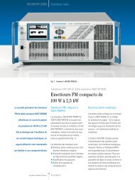
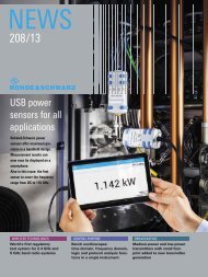
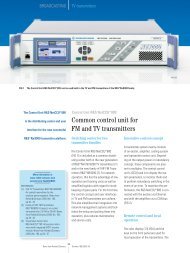
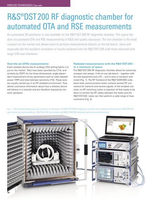
WIRELESS TECHNOLOGIES | Test cellsR&S®DST 200 <strong>RF</strong> <strong>diagnostic</strong> <strong>chamber</strong> <strong>for</strong><strong>automated</strong> <strong>OTA</strong> <strong>and</strong> <strong>RSE</strong> measurementsAn <strong>automated</strong> 3D positioner is now available <strong>for</strong> the R&S®DST 200 <strong>RF</strong> <strong>diagnostic</strong> <strong>chamber</strong>. This opens thedoor to <strong>automated</strong> <strong>OTA</strong> <strong>and</strong> <strong>RSE</strong> measurements in R&D <strong>and</strong> quality assurance. The test <strong>chamber</strong> is the mostcompact on the market <strong>and</strong> allows users to per<strong>for</strong>m measurements directly on the lab bench. Users willespecially like the excellent correlation of results achieved with the R&S®DST 200 with those obtained withlarger <strong>OTA</strong> test <strong>chamber</strong>s.Over-the-air (<strong>OTA</strong>) measurementsEvery wireless device has to undergo <strong>OTA</strong> testing be<strong>for</strong>e it isput on the market. Tests have been specified by CTIA, <strong>and</strong>similarly by 3GPP, <strong>for</strong> the three-dimensional, angle-dependentmeasurement of key parameters such as total radiatedpower (TRP) <strong>and</strong> total isotropic sensitivity (TIS). These testsare usually carried out in an <strong>RF</strong> shielded environment. Theydeliver conclusive in<strong>for</strong>mation about how a wireless devicewill behave in a network <strong>and</strong> are there<strong>for</strong>e required by networkoperators.Radiated measurements with the R&S®DST200 –in a minimum of spaceThe R&S®DST200 <strong>RF</strong> <strong>diagnostic</strong> <strong>chamber</strong> allows <strong>for</strong> extremelycompact test setups. It fits on any lab bench – together withthe test equipment <strong>and</strong> a PC – <strong>and</strong> is easy to transport <strong>and</strong>install (Fig. 1). The <strong>RF</strong> frontend of the R&S®CMW500 wideb<strong>and</strong>radio communication tester contains several <strong>RF</strong> connectors<strong>for</strong> transmit <strong>and</strong> receive signals. In the simplest scenario,no <strong>RF</strong> switching matrix is required; all that needs to bedone is connect the <strong>RF</strong> cables between the tester <strong>and</strong> theR&S®DST200. Users can then per<strong>for</strong>m a wide range of measurements(Fig. 2).Fig. 1 <strong>OTA</strong> measurements requiring a minimum of lab space: the R&S®DST200 <strong>RF</strong> <strong>diagnostic</strong> <strong>chamber</strong> with <strong>automated</strong> 3D positioner, R&S®OSP130open switch <strong>and</strong> control plat<strong>for</strong>m, R&S®ESU EMI test receiver <strong>and</strong> R&S®CMW500 wideb<strong>and</strong> radio communication tester.16
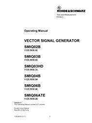
WIRELESS TECHNOLOGIES | Test cellsKey component: the automatic 3D positionerThe new, optional R&S®DST-B160 <strong>automated</strong> 3D positioner(Fig. 3), <strong>for</strong> which Rohde&Schwarz has a patent pending, isthe automatic version of the existing R&S®DST-B150 manual3D positioner. The equipment under test (EUT) is attachedto a removable support at the center of the positioner <strong>and</strong>is rotated by two servomotors about the azimuth <strong>and</strong> theelevation axes. An optical sensor ensures high positioningaccuracy, allowing both axes of rotation to be automaticallyreset to a defined start position. The <strong>automated</strong> 3D positioneris remotely controlled via its RS-232-C interface. TheR&S®AMS32 <strong>OTA</strong> per<strong>for</strong>mance measurement software <strong>and</strong>the R&S®EMC32 EMC measurement software include drivers<strong>for</strong> this interface.The servomotors <strong>and</strong> the motor control unit are accommodatedin the <strong>RF</strong> shielded bottom compartment of theR&S®DST200, preventing EMI leakage to the outside whichcould affect receiver sensitivity measurements. The positioneris made of a very low relative permittivity material to minimizefield perturbation in the EUT quiet zone.New, cross-polarized test antennaIn <strong>OTA</strong> <strong>and</strong> <strong>RSE</strong> measurements, a series of tests are per<strong>for</strong>medduring which the EUT transmits or receives ϕ <strong>and</strong> θorthogonally polarized fields. Rohde&Schwarz now offersan antenna suitable <strong>for</strong> per<strong>for</strong>ming these measurements:the new R&S®DST-B210 cross-polarized test antenna. It hastwo sections arranged at right angles <strong>and</strong> connected to two<strong>RF</strong> ports. The compact antenna achieves broadb<strong>and</strong> radiationcharacteristics in the frequency range from 70 MHz to 12 GHz<strong>and</strong> features a high cross-polarization ratio. The measurementdistance between the center of the 3D positioner <strong>and</strong> the testantenna is approx. 280 mm. Path loss calibration tables <strong>for</strong> alltest antennas compatible with the R&S®DST200 can be foundon the Rohde&Schwarz website. These tables can be used tocarry out high-precision absolute-level measurements. Testantennas are easily interchanged after opening the top coverof the R&S®DST200.Typical measurementsA-GPS testingCompared to st<strong>and</strong>alone GPS, assisted GPS (A-GPS) reducesthe time needed to calculate the position of a wireless device.In addition to satellite in<strong>for</strong>mation, A-GPS uses in<strong>for</strong>mationfrom the base station, such as accurate coordinates of the cellbase stations <strong>and</strong> precise time in<strong>for</strong>mation. A-GPS capabilityis a key requirement in order to meet the US Federal CommunicationsCommission (FCC) wireless 911 rules requiring serviceproviders to deliver fast <strong>and</strong> reliable location in<strong>for</strong>mationeven under poor signal conditions.The new R&S®DST-B160 <strong>automated</strong> 3D positioner <strong>and</strong> theR&S®DST-B210 cross-polarized test antenna are m<strong>and</strong>atoryoptions <strong>for</strong> per<strong>for</strong>ming A-GPS measurements with theR&S®DST200. The R&S®SMU200 vector signal generator simulateseight satellites, whose downlink signals are applied tothe test antenna in the R&S®DST200 in the ϕ <strong>and</strong> θ polarizationplanes (Fig. 4, example 3). The EUT extracts in<strong>for</strong>mationsuch as position data <strong>and</strong> received signal level from the satellitedata <strong>and</strong> sends it to the R&S®CMU200 universal radiocommunication tester via a cellular link.A-GPS measurements in line with CTIA 3.1 can be very timeconsuming.Testing multist<strong>and</strong>ard smartphones takes severalMeasurement<strong>OTA</strong> SISO<strong>OTA</strong> MIMODescriptionOver-the-air per<strong>for</strong>mance test in line with CTIA 3.1 TRP <strong>and</strong> TIS,GSM, WCDMA, CDMA 2000®, LTEOver-the-air per<strong>for</strong>mance test:transmit diversity, spatial multiplexing modesA-GPS Assisted GPS per<strong>for</strong>mance test in line with CTIA 3.1Coexistence Simultaneous operation of two cellular or wireless services (e. g.GSM <strong>and</strong> WLAN)DesenseVerification of <strong>OTA</strong> sensitivity degradation caused by internal EUTEMI sources (self-interference)EMI scan<strong>RSE</strong>Quick detection of EMI sources within the <strong>RF</strong> operating b<strong>and</strong>(in-b<strong>and</strong> emissions)Radiated spurious emissions measurement, e. g. to verify compliancewith specified limits in line with ETSI EN 301 908 (WCDMA) orsimilar st<strong>and</strong>ardsFig. 2 The R&S®DST200 <strong>RF</strong> <strong>diagnostic</strong> <strong>chamber</strong> enables a wide range ofmeasurements in R&D, quality assurance <strong>and</strong> product qualification.Fig. 3 The R&S®DST-B160 <strong>automated</strong> 3D positioner.NEWS 205/12 17
WIRELESS TECHNOLOGIES | Test cellshours, <strong>for</strong> example. The compact R&S®DST200 makes it possibleto per<strong>for</strong>m such measurements right on the lab bench.Product optimization takes place in the lab, <strong>and</strong> developersno longer require constant access to large <strong>OTA</strong> test <strong>chamber</strong>s,which are often not available at short notice.<strong>RSE</strong> measurements –m<strong>and</strong>atory <strong>for</strong> all wireless devicesAll wireless devices need to be tested <strong>for</strong> radiated harmonicsof the carrier frequency or other spurious emissions (radiatedspurious emissions, <strong>RSE</strong>). Measured values must complywith specified limits in line with 3GPP, ETSI or FCC st<strong>and</strong>ards,<strong>for</strong> example. <strong>RSE</strong> measurements can be made using a simpletest setup with the R&S®DST200, an R&S®CMW500<strong>and</strong> an R&S®ESU EMI test receiver (Fig. 4, example 4). TheR&S®OSP130 open switch <strong>and</strong> control plat<strong>for</strong>m connectsthe ϕ or θ polarization plane of the test antenna to the testreceiver input.MIMO per<strong>for</strong>mance testing made easyThe per<strong>for</strong>mance gain achieved with 2×2 MIMO in the downlink– data throughput twice as high as with SISO – has to beverified at various stages in a product’s life cycle:❙❙In R&D, e.g. during antenna design❙❙In production, <strong>for</strong> quality assurance❙❙In servicing, <strong>for</strong> quality assurance❙❙In qualification measurementsFig. 4 Four example test setups <strong>and</strong> results <strong>for</strong> various radiated measurements with the R&S®DST200 <strong>RF</strong> <strong>diagnostic</strong> <strong>chamber</strong>.Example 1: <strong>OTA</strong> per<strong>for</strong>mance test; TRP, GSM900UL (ϕ polarized)UL (θ polarized)DL¸CMW 500R&S®DST 200 (R&S®DST-B160,R&S®DST-B210, R&S®DST-B270)Example 2: MIMO <strong>OTA</strong> per<strong>for</strong>mance test; transmit diversity, LTE¸CMW 500DL 2(θ polarized)DL 1 (ϕ polarized)ULCCDF in %11010090807060504030201000 20 40 60 80 100Data throughput in %¸DST 200 (¸DST-B160,¸DST-B210, ¸DST-B270)CCDF at –105.00 dBmCCDF at –123.50 dBmCCDF at –124.50 dBmCCDF at –124.00 dBmCCDF at –122.50 dBmCCDF at –123.00 dBm18
WIRELESS TECHNOLOGIES | Test cellsPass/fail measurements <strong>and</strong> qualification measurements onMIMO-enabled wireless devices can be per<strong>for</strong>med usinga compact <strong>and</strong> simple test setup with the R&S®DST200<strong>RF</strong> <strong>diagnostic</strong> <strong>chamber</strong> (Fig. 4, example 2). All LTE parameterscan be configured with the R&S®AMS32 measurementsoftware <strong>and</strong> the R&S®AMS32-K31 option (Fig. 5). The twodownlink signals from the R&S®CMW500, which simulatesthe base station, are connected to the R&S®DST-B210 crosspolarizedtest antenna. The <strong>automated</strong> 3D positioner alignsthe EUT in any desired orientation in the polar coordinate systemto provide a complete picture of the spatial MIMO characteristics.Receiver sensitivity is plotted in a 3D diagram thatreveals any sensitivity degradation in partial areas. The averagedata throughput is plotted versus the received signal level.LTE parameterLTE b<strong>and</strong>Settings <strong>for</strong> LTE link1 to 41, FDD, TDD, depending on EUT capabilitiesRadio channels e. g. 5180 to 5279 <strong>for</strong> LTE FDD 13ModulationResource blocks 1 to 100Start of resource block 0 to 99Transport block size index 0 to 26B<strong>and</strong>widthMIMO modeQSPK, 16QAM, 64QAM1.4 / 3 / 5 / 10 / 15 / 20 MHztransmit diversity, open <strong>and</strong> closed loop spatialmultiplexingFig. 5 Configuration of MIMO measurements using the R&S®AMS32 <strong>OTA</strong>per<strong>for</strong>mance measurement software <strong>and</strong> the R&S®AMS32-K31 option.Example 3: A-GPS testGPS (ϕ polarized)GPS (θ polarized)¸OSP130¸SMU 200¸CMU 200Common linkDL / UL¸DST 200 (¸DST-B160,¸DST-B210, ¸DST-B270)Example 4: <strong>RSE</strong> test¸OSP130¸ESU8¸CMW 500Highpass filterϕ polarizedθ polarizedCommon linkDL / UL¸DST 200 (¸DST-B160,¸DST-B210, ¸DST-B270)Level in dBm–25<strong>RSE</strong> limit value–30–35–40–45–50–55–60–65–70–75–802.2 2.5 3 3.5 4 4.5 5 5.5 6 6.5 7 7.5 8Frequency in GHzNEWS 205/12 19
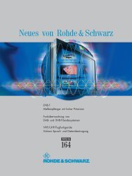
WIRELESS TECHNOLOGIES | Test cellsExcellent correlation of results between theR&S®DST200 <strong>and</strong> larger <strong>OTA</strong> test <strong>chamber</strong>sFig. 6 reveals statistical per<strong>for</strong>mance, showing the cumulativedistribution functions (CDF) <strong>for</strong> the results obtained with threedifferent test <strong>chamber</strong>s. The EUT was operated in LTE MIMOtransmit diversity mode, <strong>and</strong> receiver sensitivity was measuredwith the EUT set to six spatial orientations. The measurementsmade with the R&S®DST200 <strong>RF</strong> <strong>diagnostic</strong> <strong>chamber</strong>were repeated in order to verify reproducibility of resultsobtained with the test <strong>chamber</strong>.The best statistical sensitivity was obtained with the <strong>OTA</strong>reference test <strong>chamber</strong> (5 m × 5 m × 5 m), with 50 % ofall antenna constellations yielding at least 90 % of themaximum data throughput at a downlink power density ofP iso≈ –127 dBm/15 kHz referenced to an ideal isotropic radiator.The R&S®R-Line compact test <strong>chamber</strong> (1.7 m × 1.6 m ×2.2 m) <strong>and</strong> the R&S®DST200 delivered sensitivity 1 dB <strong>and</strong>2 dB lower, respectively, <strong>for</strong> the same test parameters. Themeasurements also exhibited a high level of reproducibility<strong>for</strong> the tests per<strong>for</strong>med with the R&S®DST200, with resultingCDF graphs differing by no more than 0.5 dB.SummaryThe R&S®DST200 <strong>RF</strong> <strong>diagnostic</strong> <strong>chamber</strong> together with itsnew options enables a wide range of <strong>automated</strong> <strong>OTA</strong> <strong>and</strong><strong>RSE</strong> test capabilities, while offering the most compact sizeon the market. The R&S®DST-B160 <strong>automated</strong> 3D positioner<strong>and</strong> the test equipment are controlled using the R&S®AMS32<strong>and</strong> R&S®EMC32 measurement software. Results are generatedin the same way as with large <strong>OTA</strong> or EMC test <strong>chamber</strong>s.These features combine to open up new applications inR&D <strong>and</strong> quality assurance in production <strong>and</strong> subsequent servicingby network operators. Rohde&Schwarz will continueto create new options <strong>and</strong> add-ons to make the R&S®DST200even more flexible.Erwin Böhler; Adam TankielunThe article starting on page 12 discusses typical <strong>RSE</strong> measurementson LTE wireless devices during development usingthe R&S®DST200 <strong>RF</strong> <strong>diagnostic</strong> <strong>chamber</strong>.Result correlation <strong>for</strong> three test <strong>chamber</strong>sCDF in %1009080706050403020100–130 –128 –126 –124 –122 –120 –118 –116P iso[dBm/15 kHz]<strong>OTA</strong> referencetest <strong>chamber</strong><strong>OTA</strong> referencetest <strong>chamber</strong>¸R-Line¸DST 200 #1¸DST 200 #1¸R-Line ¸DST 200Abbreviations3GPP 3rd Generation Partnership ProjectA-GPS Assisted global positioning systemCDF Cumulative distribution functionCTIA Cellular Telecommunications Industry AssociationDL DownlinkEMI Electromagnetic interferenceETSI European Telecommunications St<strong>and</strong>ards InstituteFCC Federal Communications CommissionFDD Frequency division duplexMIMO Multiple input multiple output<strong>OTA</strong> Over-the-air<strong>RSE</strong> Radiated spurious emissionsSISO Single input single outputTD Transmit diversityTDD Time division duplexTIS Total isotropic sensitivityTRP Total radiated powerUL UplinkWCDMA Wideb<strong>and</strong> code divison multiple accessFig. 6 CDF results obtained with three different <strong>RF</strong> test <strong>chamber</strong>s <strong>for</strong>receiver per<strong>for</strong>mance tests in LTE transmit diversity mode.20