R&S®DST200 RF diagnostic chamber for automated OTA and RSE ...
R&S®DST200 RF diagnostic chamber for automated OTA and RSE ...
R&S®DST200 RF diagnostic chamber for automated OTA and RSE ...

Create successful ePaper yourself
Turn your PDF publications into a flip-book with our unique Google optimized e-Paper software.
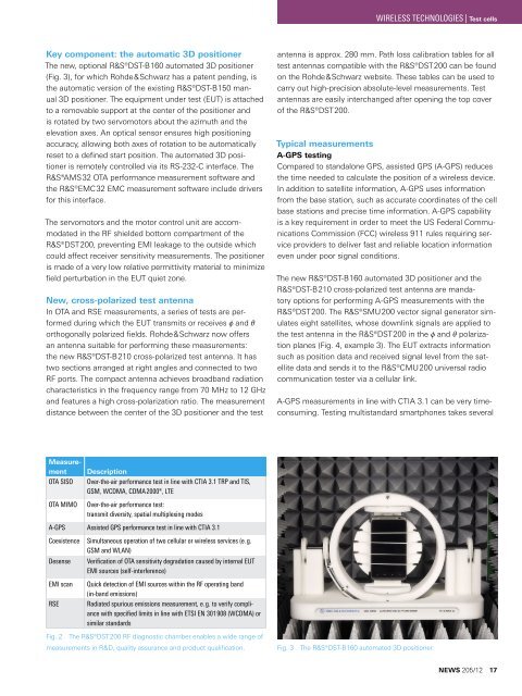
WIRELESS TECHNOLOGIES | Test cellsKey component: the automatic 3D positionerThe new, optional R&S®DST-B160 <strong>automated</strong> 3D positioner(Fig. 3), <strong>for</strong> which Rohde&Schwarz has a patent pending, isthe automatic version of the existing R&S®DST-B150 manual3D positioner. The equipment under test (EUT) is attachedto a removable support at the center of the positioner <strong>and</strong>is rotated by two servomotors about the azimuth <strong>and</strong> theelevation axes. An optical sensor ensures high positioningaccuracy, allowing both axes of rotation to be automaticallyreset to a defined start position. The <strong>automated</strong> 3D positioneris remotely controlled via its RS-232-C interface. TheR&S®AMS32 <strong>OTA</strong> per<strong>for</strong>mance measurement software <strong>and</strong>the R&S®EMC32 EMC measurement software include drivers<strong>for</strong> this interface.The servomotors <strong>and</strong> the motor control unit are accommodatedin the <strong>RF</strong> shielded bottom compartment of theR&S®DST200, preventing EMI leakage to the outside whichcould affect receiver sensitivity measurements. The positioneris made of a very low relative permittivity material to minimizefield perturbation in the EUT quiet zone.New, cross-polarized test antennaIn <strong>OTA</strong> <strong>and</strong> <strong>RSE</strong> measurements, a series of tests are per<strong>for</strong>medduring which the EUT transmits or receives ϕ <strong>and</strong> θorthogonally polarized fields. Rohde&Schwarz now offersan antenna suitable <strong>for</strong> per<strong>for</strong>ming these measurements:the new R&S®DST-B210 cross-polarized test antenna. It hastwo sections arranged at right angles <strong>and</strong> connected to two<strong>RF</strong> ports. The compact antenna achieves broadb<strong>and</strong> radiationcharacteristics in the frequency range from 70 MHz to 12 GHz<strong>and</strong> features a high cross-polarization ratio. The measurementdistance between the center of the 3D positioner <strong>and</strong> the testantenna is approx. 280 mm. Path loss calibration tables <strong>for</strong> alltest antennas compatible with the R&S®DST200 can be foundon the Rohde&Schwarz website. These tables can be used tocarry out high-precision absolute-level measurements. Testantennas are easily interchanged after opening the top coverof the R&S®DST200.Typical measurementsA-GPS testingCompared to st<strong>and</strong>alone GPS, assisted GPS (A-GPS) reducesthe time needed to calculate the position of a wireless device.In addition to satellite in<strong>for</strong>mation, A-GPS uses in<strong>for</strong>mationfrom the base station, such as accurate coordinates of the cellbase stations <strong>and</strong> precise time in<strong>for</strong>mation. A-GPS capabilityis a key requirement in order to meet the US Federal CommunicationsCommission (FCC) wireless 911 rules requiring serviceproviders to deliver fast <strong>and</strong> reliable location in<strong>for</strong>mationeven under poor signal conditions.The new R&S®DST-B160 <strong>automated</strong> 3D positioner <strong>and</strong> theR&S®DST-B210 cross-polarized test antenna are m<strong>and</strong>atoryoptions <strong>for</strong> per<strong>for</strong>ming A-GPS measurements with theR&S®DST200. The R&S®SMU200 vector signal generator simulateseight satellites, whose downlink signals are applied tothe test antenna in the R&S®DST200 in the ϕ <strong>and</strong> θ polarizationplanes (Fig. 4, example 3). The EUT extracts in<strong>for</strong>mationsuch as position data <strong>and</strong> received signal level from the satellitedata <strong>and</strong> sends it to the R&S®CMU200 universal radiocommunication tester via a cellular link.A-GPS measurements in line with CTIA 3.1 can be very timeconsuming.Testing multist<strong>and</strong>ard smartphones takes severalMeasurement<strong>OTA</strong> SISO<strong>OTA</strong> MIMODescriptionOver-the-air per<strong>for</strong>mance test in line with CTIA 3.1 TRP <strong>and</strong> TIS,GSM, WCDMA, CDMA 2000®, LTEOver-the-air per<strong>for</strong>mance test:transmit diversity, spatial multiplexing modesA-GPS Assisted GPS per<strong>for</strong>mance test in line with CTIA 3.1Coexistence Simultaneous operation of two cellular or wireless services (e. g.GSM <strong>and</strong> WLAN)DesenseVerification of <strong>OTA</strong> sensitivity degradation caused by internal EUTEMI sources (self-interference)EMI scan<strong>RSE</strong>Quick detection of EMI sources within the <strong>RF</strong> operating b<strong>and</strong>(in-b<strong>and</strong> emissions)Radiated spurious emissions measurement, e. g. to verify compliancewith specified limits in line with ETSI EN 301 908 (WCDMA) orsimilar st<strong>and</strong>ardsFig. 2 The R&S®DST200 <strong>RF</strong> <strong>diagnostic</strong> <strong>chamber</strong> enables a wide range ofmeasurements in R&D, quality assurance <strong>and</strong> product qualification.Fig. 3 The R&S®DST-B160 <strong>automated</strong> 3D positioner.NEWS 205/12 17