R&S®DST200 RF diagnostic chamber for automated OTA and RSE ...
R&S®DST200 RF diagnostic chamber for automated OTA and RSE ...
R&S®DST200 RF diagnostic chamber for automated OTA and RSE ...

You also want an ePaper? Increase the reach of your titles
YUMPU automatically turns print PDFs into web optimized ePapers that Google loves.
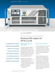
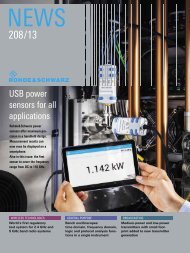
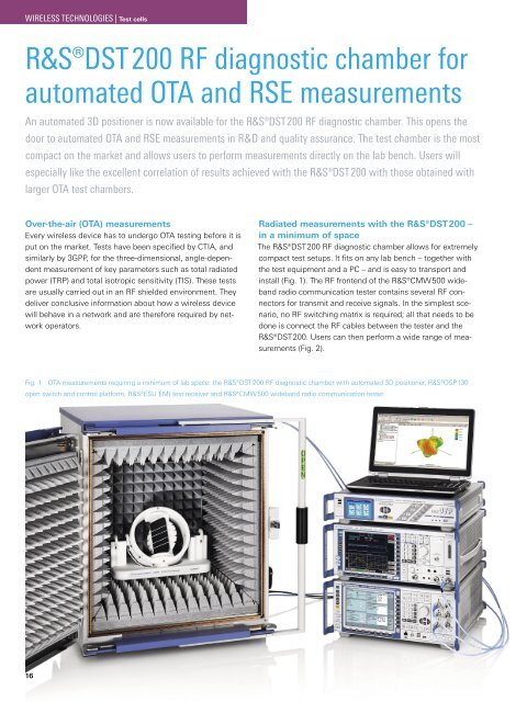
WIRELESS TECHNOLOGIES | Test cellsR&S®DST 200 <strong>RF</strong> <strong>diagnostic</strong> <strong>chamber</strong> <strong>for</strong><strong>automated</strong> <strong>OTA</strong> <strong>and</strong> <strong>RSE</strong> measurementsAn <strong>automated</strong> 3D positioner is now available <strong>for</strong> the R&S®DST 200 <strong>RF</strong> <strong>diagnostic</strong> <strong>chamber</strong>. This opens thedoor to <strong>automated</strong> <strong>OTA</strong> <strong>and</strong> <strong>RSE</strong> measurements in R&D <strong>and</strong> quality assurance. The test <strong>chamber</strong> is the mostcompact on the market <strong>and</strong> allows users to per<strong>for</strong>m measurements directly on the lab bench. Users willespecially like the excellent correlation of results achieved with the R&S®DST 200 with those obtained withlarger <strong>OTA</strong> test <strong>chamber</strong>s.Over-the-air (<strong>OTA</strong>) measurementsEvery wireless device has to undergo <strong>OTA</strong> testing be<strong>for</strong>e it isput on the market. Tests have been specified by CTIA, <strong>and</strong>similarly by 3GPP, <strong>for</strong> the three-dimensional, angle-dependentmeasurement of key parameters such as total radiatedpower (TRP) <strong>and</strong> total isotropic sensitivity (TIS). These testsare usually carried out in an <strong>RF</strong> shielded environment. Theydeliver conclusive in<strong>for</strong>mation about how a wireless devicewill behave in a network <strong>and</strong> are there<strong>for</strong>e required by networkoperators.Radiated measurements with the R&S®DST200 –in a minimum of spaceThe R&S®DST200 <strong>RF</strong> <strong>diagnostic</strong> <strong>chamber</strong> allows <strong>for</strong> extremelycompact test setups. It fits on any lab bench – together withthe test equipment <strong>and</strong> a PC – <strong>and</strong> is easy to transport <strong>and</strong>install (Fig. 1). The <strong>RF</strong> frontend of the R&S®CMW500 wideb<strong>and</strong>radio communication tester contains several <strong>RF</strong> connectors<strong>for</strong> transmit <strong>and</strong> receive signals. In the simplest scenario,no <strong>RF</strong> switching matrix is required; all that needs to bedone is connect the <strong>RF</strong> cables between the tester <strong>and</strong> theR&S®DST200. Users can then per<strong>for</strong>m a wide range of measurements(Fig. 2).Fig. 1 <strong>OTA</strong> measurements requiring a minimum of lab space: the R&S®DST200 <strong>RF</strong> <strong>diagnostic</strong> <strong>chamber</strong> with <strong>automated</strong> 3D positioner, R&S®OSP130open switch <strong>and</strong> control plat<strong>for</strong>m, R&S®ESU EMI test receiver <strong>and</strong> R&S®CMW500 wideb<strong>and</strong> radio communication tester.16
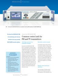
WIRELESS TECHNOLOGIES | Test cellsKey component: the automatic 3D positionerThe new, optional R&S®DST-B160 <strong>automated</strong> 3D positioner(Fig. 3), <strong>for</strong> which Rohde&Schwarz has a patent pending, isthe automatic version of the existing R&S®DST-B150 manual3D positioner. The equipment under test (EUT) is attachedto a removable support at the center of the positioner <strong>and</strong>is rotated by two servomotors about the azimuth <strong>and</strong> theelevation axes. An optical sensor ensures high positioningaccuracy, allowing both axes of rotation to be automaticallyreset to a defined start position. The <strong>automated</strong> 3D positioneris remotely controlled via its RS-232-C interface. TheR&S®AMS32 <strong>OTA</strong> per<strong>for</strong>mance measurement software <strong>and</strong>the R&S®EMC32 EMC measurement software include drivers<strong>for</strong> this interface.The servomotors <strong>and</strong> the motor control unit are accommodatedin the <strong>RF</strong> shielded bottom compartment of theR&S®DST200, preventing EMI leakage to the outside whichcould affect receiver sensitivity measurements. The positioneris made of a very low relative permittivity material to minimizefield perturbation in the EUT quiet zone.New, cross-polarized test antennaIn <strong>OTA</strong> <strong>and</strong> <strong>RSE</strong> measurements, a series of tests are per<strong>for</strong>medduring which the EUT transmits or receives ϕ <strong>and</strong> θorthogonally polarized fields. Rohde&Schwarz now offersan antenna suitable <strong>for</strong> per<strong>for</strong>ming these measurements:the new R&S®DST-B210 cross-polarized test antenna. It hastwo sections arranged at right angles <strong>and</strong> connected to two<strong>RF</strong> ports. The compact antenna achieves broadb<strong>and</strong> radiationcharacteristics in the frequency range from 70 MHz to 12 GHz<strong>and</strong> features a high cross-polarization ratio. The measurementdistance between the center of the 3D positioner <strong>and</strong> the testantenna is approx. 280 mm. Path loss calibration tables <strong>for</strong> alltest antennas compatible with the R&S®DST200 can be foundon the Rohde&Schwarz website. These tables can be used tocarry out high-precision absolute-level measurements. Testantennas are easily interchanged after opening the top coverof the R&S®DST200.Typical measurementsA-GPS testingCompared to st<strong>and</strong>alone GPS, assisted GPS (A-GPS) reducesthe time needed to calculate the position of a wireless device.In addition to satellite in<strong>for</strong>mation, A-GPS uses in<strong>for</strong>mationfrom the base station, such as accurate coordinates of the cellbase stations <strong>and</strong> precise time in<strong>for</strong>mation. A-GPS capabilityis a key requirement in order to meet the US Federal CommunicationsCommission (FCC) wireless 911 rules requiring serviceproviders to deliver fast <strong>and</strong> reliable location in<strong>for</strong>mationeven under poor signal conditions.The new R&S®DST-B160 <strong>automated</strong> 3D positioner <strong>and</strong> theR&S®DST-B210 cross-polarized test antenna are m<strong>and</strong>atoryoptions <strong>for</strong> per<strong>for</strong>ming A-GPS measurements with theR&S®DST200. The R&S®SMU200 vector signal generator simulateseight satellites, whose downlink signals are applied tothe test antenna in the R&S®DST200 in the ϕ <strong>and</strong> θ polarizationplanes (Fig. 4, example 3). The EUT extracts in<strong>for</strong>mationsuch as position data <strong>and</strong> received signal level from the satellitedata <strong>and</strong> sends it to the R&S®CMU200 universal radiocommunication tester via a cellular link.A-GPS measurements in line with CTIA 3.1 can be very timeconsuming.Testing multist<strong>and</strong>ard smartphones takes severalMeasurement<strong>OTA</strong> SISO<strong>OTA</strong> MIMODescriptionOver-the-air per<strong>for</strong>mance test in line with CTIA 3.1 TRP <strong>and</strong> TIS,GSM, WCDMA, CDMA 2000®, LTEOver-the-air per<strong>for</strong>mance test:transmit diversity, spatial multiplexing modesA-GPS Assisted GPS per<strong>for</strong>mance test in line with CTIA 3.1Coexistence Simultaneous operation of two cellular or wireless services (e. g.GSM <strong>and</strong> WLAN)DesenseVerification of <strong>OTA</strong> sensitivity degradation caused by internal EUTEMI sources (self-interference)EMI scan<strong>RSE</strong>Quick detection of EMI sources within the <strong>RF</strong> operating b<strong>and</strong>(in-b<strong>and</strong> emissions)Radiated spurious emissions measurement, e. g. to verify compliancewith specified limits in line with ETSI EN 301 908 (WCDMA) orsimilar st<strong>and</strong>ardsFig. 2 The R&S®DST200 <strong>RF</strong> <strong>diagnostic</strong> <strong>chamber</strong> enables a wide range ofmeasurements in R&D, quality assurance <strong>and</strong> product qualification.Fig. 3 The R&S®DST-B160 <strong>automated</strong> 3D positioner.NEWS 205/12 17
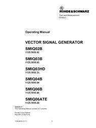
WIRELESS TECHNOLOGIES | Test cellshours, <strong>for</strong> example. The compact R&S®DST200 makes it possibleto per<strong>for</strong>m such measurements right on the lab bench.Product optimization takes place in the lab, <strong>and</strong> developersno longer require constant access to large <strong>OTA</strong> test <strong>chamber</strong>s,which are often not available at short notice.<strong>RSE</strong> measurements –m<strong>and</strong>atory <strong>for</strong> all wireless devicesAll wireless devices need to be tested <strong>for</strong> radiated harmonicsof the carrier frequency or other spurious emissions (radiatedspurious emissions, <strong>RSE</strong>). Measured values must complywith specified limits in line with 3GPP, ETSI or FCC st<strong>and</strong>ards,<strong>for</strong> example. <strong>RSE</strong> measurements can be made using a simpletest setup with the R&S®DST200, an R&S®CMW500<strong>and</strong> an R&S®ESU EMI test receiver (Fig. 4, example 4). TheR&S®OSP130 open switch <strong>and</strong> control plat<strong>for</strong>m connectsthe ϕ or θ polarization plane of the test antenna to the testreceiver input.MIMO per<strong>for</strong>mance testing made easyThe per<strong>for</strong>mance gain achieved with 2×2 MIMO in the downlink– data throughput twice as high as with SISO – has to beverified at various stages in a product’s life cycle:❙❙In R&D, e.g. during antenna design❙❙In production, <strong>for</strong> quality assurance❙❙In servicing, <strong>for</strong> quality assurance❙❙In qualification measurementsFig. 4 Four example test setups <strong>and</strong> results <strong>for</strong> various radiated measurements with the R&S®DST200 <strong>RF</strong> <strong>diagnostic</strong> <strong>chamber</strong>.Example 1: <strong>OTA</strong> per<strong>for</strong>mance test; TRP, GSM900UL (ϕ polarized)UL (θ polarized)DL¸CMW 500R&S®DST 200 (R&S®DST-B160,R&S®DST-B210, R&S®DST-B270)Example 2: MIMO <strong>OTA</strong> per<strong>for</strong>mance test; transmit diversity, LTE¸CMW 500DL 2(θ polarized)DL 1 (ϕ polarized)ULCCDF in %11010090807060504030201000 20 40 60 80 100Data throughput in %¸DST 200 (¸DST-B160,¸DST-B210, ¸DST-B270)CCDF at –105.00 dBmCCDF at –123.50 dBmCCDF at –124.50 dBmCCDF at –124.00 dBmCCDF at –122.50 dBmCCDF at –123.00 dBm18
WIRELESS TECHNOLOGIES | Test cellsPass/fail measurements <strong>and</strong> qualification measurements onMIMO-enabled wireless devices can be per<strong>for</strong>med usinga compact <strong>and</strong> simple test setup with the R&S®DST200<strong>RF</strong> <strong>diagnostic</strong> <strong>chamber</strong> (Fig. 4, example 2). All LTE parameterscan be configured with the R&S®AMS32 measurementsoftware <strong>and</strong> the R&S®AMS32-K31 option (Fig. 5). The twodownlink signals from the R&S®CMW500, which simulatesthe base station, are connected to the R&S®DST-B210 crosspolarizedtest antenna. The <strong>automated</strong> 3D positioner alignsthe EUT in any desired orientation in the polar coordinate systemto provide a complete picture of the spatial MIMO characteristics.Receiver sensitivity is plotted in a 3D diagram thatreveals any sensitivity degradation in partial areas. The averagedata throughput is plotted versus the received signal level.LTE parameterLTE b<strong>and</strong>Settings <strong>for</strong> LTE link1 to 41, FDD, TDD, depending on EUT capabilitiesRadio channels e. g. 5180 to 5279 <strong>for</strong> LTE FDD 13ModulationResource blocks 1 to 100Start of resource block 0 to 99Transport block size index 0 to 26B<strong>and</strong>widthMIMO modeQSPK, 16QAM, 64QAM1.4 / 3 / 5 / 10 / 15 / 20 MHztransmit diversity, open <strong>and</strong> closed loop spatialmultiplexingFig. 5 Configuration of MIMO measurements using the R&S®AMS32 <strong>OTA</strong>per<strong>for</strong>mance measurement software <strong>and</strong> the R&S®AMS32-K31 option.Example 3: A-GPS testGPS (ϕ polarized)GPS (θ polarized)¸OSP130¸SMU 200¸CMU 200Common linkDL / UL¸DST 200 (¸DST-B160,¸DST-B210, ¸DST-B270)Example 4: <strong>RSE</strong> test¸OSP130¸ESU8¸CMW 500Highpass filterϕ polarizedθ polarizedCommon linkDL / UL¸DST 200 (¸DST-B160,¸DST-B210, ¸DST-B270)Level in dBm–25<strong>RSE</strong> limit value–30–35–40–45–50–55–60–65–70–75–802.2 2.5 3 3.5 4 4.5 5 5.5 6 6.5 7 7.5 8Frequency in GHzNEWS 205/12 19
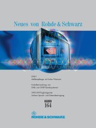
WIRELESS TECHNOLOGIES | Test cellsExcellent correlation of results between theR&S®DST200 <strong>and</strong> larger <strong>OTA</strong> test <strong>chamber</strong>sFig. 6 reveals statistical per<strong>for</strong>mance, showing the cumulativedistribution functions (CDF) <strong>for</strong> the results obtained with threedifferent test <strong>chamber</strong>s. The EUT was operated in LTE MIMOtransmit diversity mode, <strong>and</strong> receiver sensitivity was measuredwith the EUT set to six spatial orientations. The measurementsmade with the R&S®DST200 <strong>RF</strong> <strong>diagnostic</strong> <strong>chamber</strong>were repeated in order to verify reproducibility of resultsobtained with the test <strong>chamber</strong>.The best statistical sensitivity was obtained with the <strong>OTA</strong>reference test <strong>chamber</strong> (5 m × 5 m × 5 m), with 50 % ofall antenna constellations yielding at least 90 % of themaximum data throughput at a downlink power density ofP iso≈ –127 dBm/15 kHz referenced to an ideal isotropic radiator.The R&S®R-Line compact test <strong>chamber</strong> (1.7 m × 1.6 m ×2.2 m) <strong>and</strong> the R&S®DST200 delivered sensitivity 1 dB <strong>and</strong>2 dB lower, respectively, <strong>for</strong> the same test parameters. Themeasurements also exhibited a high level of reproducibility<strong>for</strong> the tests per<strong>for</strong>med with the R&S®DST200, with resultingCDF graphs differing by no more than 0.5 dB.SummaryThe R&S®DST200 <strong>RF</strong> <strong>diagnostic</strong> <strong>chamber</strong> together with itsnew options enables a wide range of <strong>automated</strong> <strong>OTA</strong> <strong>and</strong><strong>RSE</strong> test capabilities, while offering the most compact sizeon the market. The R&S®DST-B160 <strong>automated</strong> 3D positioner<strong>and</strong> the test equipment are controlled using the R&S®AMS32<strong>and</strong> R&S®EMC32 measurement software. Results are generatedin the same way as with large <strong>OTA</strong> or EMC test <strong>chamber</strong>s.These features combine to open up new applications inR&D <strong>and</strong> quality assurance in production <strong>and</strong> subsequent servicingby network operators. Rohde&Schwarz will continueto create new options <strong>and</strong> add-ons to make the R&S®DST200even more flexible.Erwin Böhler; Adam TankielunThe article starting on page 12 discusses typical <strong>RSE</strong> measurementson LTE wireless devices during development usingthe R&S®DST200 <strong>RF</strong> <strong>diagnostic</strong> <strong>chamber</strong>.Result correlation <strong>for</strong> three test <strong>chamber</strong>sCDF in %1009080706050403020100–130 –128 –126 –124 –122 –120 –118 –116P iso[dBm/15 kHz]<strong>OTA</strong> referencetest <strong>chamber</strong><strong>OTA</strong> referencetest <strong>chamber</strong>¸R-Line¸DST 200 #1¸DST 200 #1¸R-Line ¸DST 200Abbreviations3GPP 3rd Generation Partnership ProjectA-GPS Assisted global positioning systemCDF Cumulative distribution functionCTIA Cellular Telecommunications Industry AssociationDL DownlinkEMI Electromagnetic interferenceETSI European Telecommunications St<strong>and</strong>ards InstituteFCC Federal Communications CommissionFDD Frequency division duplexMIMO Multiple input multiple output<strong>OTA</strong> Over-the-air<strong>RSE</strong> Radiated spurious emissionsSISO Single input single outputTD Transmit diversityTDD Time division duplexTIS Total isotropic sensitivityTRP Total radiated powerUL UplinkWCDMA Wideb<strong>and</strong> code divison multiple accessFig. 6 CDF results obtained with three different <strong>RF</strong> test <strong>chamber</strong>s <strong>for</strong>receiver per<strong>for</strong>mance tests in LTE transmit diversity mode.20