R&S®ETL TV Analyzer - Product Brochure - Rohde & Schwarz
R&S®ETL TV Analyzer - Product Brochure - Rohde & Schwarz
R&S®ETL TV Analyzer - Product Brochure - Rohde & Schwarz
You also want an ePaper? Increase the reach of your titles
YUMPU automatically turns print PDFs into web optimized ePapers that Google loves.
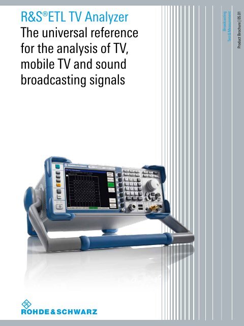
R&S®GerätenameR&S®ETL <strong>TV</strong> <strong>Analyzer</strong>und The universal Bezeichnung referencefor Specificationsthe analysis of <strong>TV</strong>,mobile <strong>TV</strong> and soundbroadcasting signalsBroadcastingTest & Measurement<strong>Product</strong> Data <strong>Brochure</strong> Sheet | | 05.01
R&S®ETL<strong>TV</strong> <strong>Analyzer</strong>At a glanceThe R&S®ETL <strong>TV</strong> analyzer stands for all-in-one.The R&S®ETL combines the functionality of a <strong>TV</strong>and FM (radio) signal analyzer, a video and MPEGTS analyzer and a spectrum analyzer in a singleinstrument. The R&S®ETL also contains generatorsto create analog video signals, audio signals andMPEG-2 transport streams.The R&S®ETL's innovative instrument concept facilitatesthe flexible integration of demodulators for analog anddigital <strong>TV</strong> standards as well as sound broadcasting. All ofthe demodulators work in realtime; fast signal processingallows comprehensive, extremely accurate measurements.Its wide range of functions and flexible configuration makethe R&S®ETL <strong>TV</strong> analyzer the universal reference for theanalysis of <strong>TV</strong> signals – for <strong>TV</strong> and cable network operators,transmitter manufacturers, service technicians andregulatory authorities.The R&S®ETL <strong>TV</strong> analyzer has primarily been designedto provide reproducible, high-quality analysis of <strong>TV</strong> andsound broadcasting signals such as are needed at thetransmitter site, at the cable headend or for quality assuranceduring production.The R&S®ETL is ideal for both stationary and portableuse. The compact, rugged housing makes outdoor usepossible, e.g. for coverage measurements within a terrestrial<strong>TV</strong> or sound broadcasting transmitter network.2
Key facts❙❙Frequency range from 500 kHz to 3 GHz❙❙<strong>TV</strong>, FM (radio), video, audio, MPEG-2 transport streamand spectrum analysis in a single box❙❙FPGA and chip-based realtime demodulators for analog<strong>TV</strong>, DVB-T, DVB-T2, DVB-H, ATSC/8VSB, ATSC MobileD<strong>TV</strong>, ISDB-T (B), J.83/A/C, DVB-C, J.83/B, DTMB, T-DMB/DAB and FM (radio)❙❙Baseband outputs❙❙Preselection with additional 75 Ω RF input❙❙Video signal generator❙❙Audio signal generator❙❙MPEG-2 transport stream generator/recorder❙❙Support of power sensors❙❙DC input and rechargeable Li-ion batteryMain applicationsAcceptance testing, maintenance and servicing of<strong>TV</strong>, mobile <strong>TV</strong>, DAB and FM transmitters❙❙Precise analysis of the signal quality at the transmitteroutput❙❙Measurements to optimize transmitter operatingparameters❙❙Measurement of spurious emissions❙❙Detection of faults❙❙Documentation of signal parameters❙❙Remote maintenance via IP networks with the RemoteDesktop function▷▷page 6Quality assurance during the production ofmodulators and <strong>TV</strong>, DAB and FM transmitters❙❙Reproducible analysis of the signal quality of modulatorsand transmitters▷▷page 7Optimization of <strong>TV</strong>, mobile <strong>TV</strong>, DAB and FMtransmitter networks❙❙Measurement of receive levels and signal quality at thereception site❙❙Checking and optimization of digital single-frequencynetworks (SFN)❙❙Systematic determination of receive quality in thetransmission area (coverage measurement)▷▷page 8<strong>Rohde</strong> & <strong>Schwarz</strong> R&S®ETL <strong>TV</strong> <strong>Analyzer</strong> 3
R&S®ETL<strong>TV</strong> <strong>Analyzer</strong>Benefits and keyfeaturesAll-in-one solution❙❙All required measurement equipment in a compactinstrument❙❙Short learning curve due to uniform operating concept❙❙Fast and comprehensive signal analysis❙❙Simplified documentation of measurement results❙❙Excellent price/performance ratio▷▷page 10FPGA-based realtime demodulators❙❙Simple implementation of new standards with firmwareupdates❙❙Easy integration of multiple standards in a singleinstrument❙❙Seamless signal analysis through realtime demodulation❙❙Analysis and provision of baseband signals (video, audio,ETI, MPEG-2 TS)▷▷page 12Comprehensive analysis of analog <strong>TV</strong> signals❙❙Ideal for the transition from analog to digital <strong>TV</strong>❙❙Overview of the most important parameters❙❙Measurements for evaluating modulator quality at thetransmitter or cable headend❙❙<strong>TV</strong> picture for fast visual inspection of transmission links▷▷page 14Comprehensive analysis of digital <strong>TV</strong> and mobile<strong>TV</strong> signals❙❙Overview of the most important parameters❙❙Spurious emissions quickly detected with integratedspectrum analyzer❙❙Constellation diagram with high processing speed fordetecting short-duration interferers❙❙Measurements for optimizing transmitters andmodulators▷▷page 16Analysis functions for second-generation<strong>TV</strong> standards – DVB‐T2, ATSC MD<strong>TV</strong>❙❙DVB-T2, realtime signal analysis❙❙Wide-ranging analysis functions❙❙Prepared for multi-PLP and MISO❙❙ATSC MD<strong>TV</strong> realtime signal analysis❙❙Analysis of signaling parameters and services❙❙Measurements to optimize single-frequency networks▷▷page 18Precise analysis of digital single- frequencynetworks (SFN)❙❙High-precision display of channel impulse response❙❙Simple identification of echoes using tabular lists andmarker functions❙❙Extended time domain for faraway post-echoes❙❙Efficient measurement of frequency drifts within an SFN▷▷page 204
High-performance analysis of FM (radio) andaudio signals❙❙Analysis of RF and MPX signals at the transmitter or inthe field❙❙High-quality SNR measurement with high SNR frontend❙❙Integrated audio analysis▷▷page 22MPEG-2 transport stream analysis❙❙Checking of input and output signals at the transmitter orcable headend❙❙Analysis in line with ETSI TR 101290, priorities 1 to 3❙❙Table interpreter and in-depth analysis❙❙Data broadcast analysis including ESG❙❙Software and hardware decoder for MPEG-2 and H.264▷▷page 24Measurements for cable <strong>TV</strong> networks❙❙CSO, CTB and C/N❙❙Frequency response measurement❙❙Ingress measurement to detect interferers▷▷page 26Automatic measurements and documentation❙❙R&S®TxCheck measurement software for DVB-T, DVB-T2,DVB-H, ATSC/8VSB, ISDB-T (B), J.83/A/B/C and FM (radio)❙❙R&S®TPCHECK transposer measurement software forDVB-T and DVB-H❙❙R&S®<strong>TV</strong>SCAN measurement software for measuringcable <strong>TV</strong> systems and DVB-T/DVB-T2 transmissions❙❙Long-term documentation of measured values for D<strong>TV</strong>,DAB and FM (radio)▷▷page 28Precise power measurement❙❙Support of R&S®NRP-Zxx power sensors▷▷page 34Flexible option concept❙❙Modules for easy upgrading by user❙❙Interfaces for enhanced functionality▷▷page 35Reference signals for transmitters and modulators❙❙MPEG TS generator and recorder❙❙Analog <strong>TV</strong> video generator❙❙Audio generator▷▷page 36Ideal for portable use❙❙High-contrast, daylight-compatible display❙❙Rugged housing with edge protection❙❙DC power supply and replaceable, rechargeable batteryfor use in vehicles and the field❙❙Compact design and low weight with wide range offunctions▷▷page 38Integration of spectrum measurements in <strong>TV</strong> andsound broadcasting signal analysis❙❙Full-featured spectrum analyzer❙❙Measurement of transmission channel power, adjacentchannel power and harmonics❙❙Crest factor❙❙Built-in tracking generator for measuring filters andamplifiers❙❙Transducer tables and antenna factors taken into account▷▷page 32<strong>Rohde</strong> & <strong>Schwarz</strong> R&S®ETL <strong>TV</strong> <strong>Analyzer</strong> 5
Acceptance testing,maintenanceand servicing of <strong>TV</strong>,mobile <strong>TV</strong>, DAB andFM transmittersThe quality of transmitter networks depends on the optimaland error-free operation of each individual transmitter. TheR&S®ETL <strong>TV</strong> analyzer offers a range of functions to maintainthe high quality of the network during acceptance testing,maintenance and servicing of transmitters. The same holdstrue for cable <strong>TV</strong> networks and their modulators used incable headends.Precise analysis of the signal quality at thetransmitter outputThe R&S®ETL's high-quality RF frontend and subsequentdigital signal processing help ensure accurate, closetolerancemeasurement results. A contributing factor isthe R&S®ETL system performance, with a video signal-tonoiseratio of > 60 dB (analog <strong>TV</strong>) and an intrinsic MER of> 40 dB (digital <strong>TV</strong>), providing enough margin for measurementswith relatively low inherent error. The precision of theR&S®ETL can be increased by using an internal temperaturecompensatedoscillator or external power sensors supportedby the R&S®ETL.Measurements to optimize transmitter operatingparametersThe R&S®ETL measurement functions are not limited to afew key parameters. The <strong>TV</strong> analyzer also provides othermeasurements that help the user optimally set up theoperating parameters, such as frequency spectrum, modulationparameters and output power.Measurement of spurious emissionsSpurious emissions at the transmitter or cable headendmust be measured to make sure adjacent channels arenot adversely affected. One of the main advantages of theR&S®ETL is the built-in spectrum analyzer functionalitythat makes it possible to measure shoulder attenuation,adjacent channel power and harmonics without additionalmeasurement equipment.Detection of faultsThe very difficult task of finding sporadic faults is easy withthe R&S®ETL. Fast realtime signal processing captures evensporadic interference. The measurement log option is especiallyuseful. Important parameters are logged even overlonger time periods. Deviations from nominal values areclearly shown.Documentation of signal parametersThe R&S®ETL offers various options for documenting signalparameters. It only takes seconds to create and savescreenshots, either internally or to an external storagemedium. These tasks can be conveniently accomplishedwith the R&S®TxCheck measurement software. Thesoftware automatically measures DVB-T, DVB-T2, DVB-H,ATSC/8VSB, ISDB-T (B), DVB-C, J.83/B/C and FM (radio)signals, evaluates the results and documents them in areport.Remote maintenance via IP networks with theRemote Desktop functionA service technician is not always available at the transmittersite to quickly analyze the cause of faults. In this case,the R&S®ETL can be controlled remotely via a LAN interface.The Remote Desktop function allows specialists to carryout all measurements from a remote location, such as acentral service center, as if they were on site.6
Quality assuranceduring the productionof modulatorsand <strong>TV</strong>, DAB andFM transmittersThe quality level of modulators and transmitters must bemaintained on the production line, even when transmissionstandards frequently change. Numerous demodulatorsand measurement functions for various standards can beinstalled on the compact R&S®ETL <strong>TV</strong> analyzer multistandardplatform. Users can quickly switch between these functions,either manually or via the remote control interface whichprovides the appropriate remote commands for all availablestandards. The R&S®ETL can be easily integrated into automaticmeasurement systems.Reproducible analysis of the signal quality ofmodulators and transmittersIt is only possible to reliably determine fluctuations in theproduction quality when the quality is regularly checkedunder reproducible conditions.This is one of the strong points of the R&S®ETL. Combiningthe measurement functions of several instruments in asingle instrument ensures that measurements are alwaysmade with matching settings. All instrument settings canbe saved and reloaded at any point in time.The user can define PASS/FAIL limits for almost everymeasurement parameter. This makes it easier to evaluatethe production quality and create test logs.Parameter list with user-definable limits.<strong>Rohde</strong> & <strong>Schwarz</strong> R&S®ETL <strong>TV</strong> <strong>Analyzer</strong> 7
Optimization of <strong>TV</strong>,mobile <strong>TV</strong>, DABand FM transmitternetworksMeasurement of receive levels and signal quality atthe reception siteWhen a new broadcast transmitter network is put intooperation, it is especially important that the quality of thetransmitter coverage fulfills the network planning specifications.While the main criterion for analog transmitternetworks is a sufficiently high receive level, digital transmitternetworks have even more criteria that must be takeninto account.For field measurements, the R&S®ETL can be equippedwith an internal preselection to improve receive dynamicsand input sensitivity. As a result, the R&S®ETL is perfectlyable to analyze all relevant signal parameters in the field.Checking and optimization of digital singlefrequencynetworks (SFN)All over the world, digital networks are replacing analognetworks. Most digital networks are operated as singlefrequencynetworks in order to achieve high coveragequality. The R&S®ETL's high-precision SFN measurementsprovide network operators with all the tools they need tocheck and optimize SFN networks.Echo pattern of a DVB-T, DVB-H single-frequnecy network.8
Systematic determination of receive quality in thetransmission area (coverage measurement)Test vehicles are often used when measuring the receivequality of the transmission area. While they are systematicallydriven over the entire coverage area, important signalparameters and their location are measured and logged.The R&S®BCDRIVE for drive tests software provides asolution that makes it possible to capture and record thesignal quality while driving and export it for viewing the recordon a map.For the most common digital standards, the R&S®ETL canbe integrated into the R&S®BCDRIVE drive test system tohelp find problematic receive locations and determine thecause of reduced signal quality.Presentation and analysis of measurement results in the map view.Status messages at a glance during a drive test.<strong>Rohde</strong> & <strong>Schwarz</strong> R&S®ETL <strong>TV</strong> <strong>Analyzer</strong> 9
All-in-one solutionAll required measurement equipment in a compactinstrumentThe R&S®ETL <strong>TV</strong> analyzer can perform measurements thatused to require several separate measuring instruments.The R&S®ETL combines the functionality of a <strong>TV</strong> test receiver,a spectrum analyzer, an MPEG TS analyzer and other instrumentsproviding users with all the tools they need in a single,compact instrument.Short learning curve due to uniform operating conceptIntegrating several T&M instruments into one makes operationconsiderably easier. Similar functions have similaruser prompts. The uniform operating concept means thatthe learning curve for the R&S®ETL is very short and the riskof operator error is reduced.Fast and comprehensive signal analysisWhen an error occurs in a transmitter network, quick actionis required. The R&S®ETL's comprehensive signal analysisfunctions allow users to quickly find the cause of errors –without any additional T&M equipment.Menu for selecting the measurement mode.The R&S®ETL also helps save time when performing everyday,routine tasks because it is fast and easy to switchbetween the various T&M functions; no changes need tobe made to instrument settings or test setup.All-in-one solutionVideoanalyzerFM (radio)analyzer<strong>TV</strong> analyzerA<strong>TV</strong><strong>TV</strong> analyzerD<strong>TV</strong>MPEG TSanalyzerMPEG TSgenerator/recorderAudioanalyzerVideogeneratorAudiogeneratorPowermeterSpectrumanalyzerMPEG decoder10
Simplified documentation of measurement resultsWhen several T&M instruments are used to collect data,various data formats, storage media or remote commandsare usually needed to document the results in a report.The all-in-one concept of the R&S®ETL makes documentationof measurement results easier because it is based on access to common storage media, uniform operation andstandardized remote commands.This is illustrated by the R&S®TxCheck measurement software,which runs on the <strong>TV</strong> analyzer itself. R&S®TxCheckautomatically executes the measurements the user wants,and documents the measurement results and traces in acommon report.Excellent price/performance ratioIn addition to shortening the learning curve and makingeveryday work more efficient, the R&S®ETL's all-in-oneconcept also yields an excellent price/performance ratio.Combining several T&M functions on one hardware platformdrastically lowers purchase costs. Another cost-savingbenefit of the all-in-one concept is the significant reductionin effort necessary for regular calibration.R&S®TxCheck automatic measurement tool.Span menu in <strong>TV</strong> analyzer mode ...... and in spectrum analyzer mode.<strong>Rohde</strong> & <strong>Schwarz</strong> R&S®ETL <strong>TV</strong> <strong>Analyzer</strong> 11
FPGA-based realtimedemodulatorsThe central component in a <strong>TV</strong> analyzer is the demodulator.The demodulator determines which analyses in whatquality can be carried out. Chip-based demodulators donot usually offer the required quality nor do they havethe interfaces required for professional T&M applications.That's why <strong>Rohde</strong> & <strong>Schwarz</strong> uses its own FPGA-baseddemodulators in the R&S®ETL.Simple implementation of new standards withfirmware updatesIn addition to quality, another advantage of FPGA-baseddemodulators is that they make it easy to implement newtransmission standards. Usually, only a firmware updateand an installation key are required. This provides a highdegree of investment protection and flexibility.Easy integration of multiple standards in a singleinstrumentIt is not unusual for transmitter network operators in thesame coverage area to broadcast different standards, oftenfrom the same site. Today, analog <strong>TV</strong> can be foundadjacent to digital <strong>TV</strong>, and analog sound broadcastingadjacent to digital audio broadcasting. The R&S®ETL isan ideal, cost-effective solution for transmitter measurements.The FPGA-based demodulators in the R&S®ETLallow multiple <strong>TV</strong> and sound broadcasting standards to beeasily integrated, which eliminates the need for investing inseveral instruments. The R&S®ETL hardware can also be updatedto add other standards to cover future requirements.R&S®ETL multistandard platformAnalog <strong>TV</strong>DVB-TDVB-HISDB-TATSC/8VSBT-DMB/DABFM(radio)FPGA(demodulator)FPGA(extension)R&S®ETL-B300J.83/A/B/CDVB-T2 ATSC MD<strong>TV</strong> DTMBFPGA functionsASIC functions12
Seamless signal analysis through realtimedemodulationOne of the basic principles of the R&S®ETL <strong>TV</strong> analyzer isrealtime demodulation for practically seamless signal analysisto detect even sporadic interference.Analysis and provision of baseband signals (video,audio, ETI, MPEG-2 TS)Realtime demodulators are important for seamless signalanalysis. They also allow analysis of baseband signalssuch as video, audio and those from a digital transportstream. Baseband signals can be analyzed internally withthe R&S®ETL or externally with additional instruments. TheR&S®ETL has numerous interfaces where the demodulatedsignals are made.Comparision between offline and realtime analysisOffline analysisSample01010101010101010101010101010101MeasurementRealtime analysisMenu for selectingdigital standards.Sample01010101010101010101010101010101010101010101MeasurementtMenu for selectinganalog <strong>TV</strong> standards.<strong>Rohde</strong> & <strong>Schwarz</strong> R&S®ETL <strong>TV</strong> <strong>Analyzer</strong> 13
Comprehensiveanalysis of analog<strong>TV</strong> signalsThe R&S®ETL standard version comes with a range ofelementary measurements for analyzing analog <strong>TV</strong> signals.The video analyzer functionality needed at the transmittersite or at the cable headend can be added to the R&S®ETL.Ideal for the transition from analog to digital <strong>TV</strong>Digitization of terrestrial transmitter networks and cable <strong>TV</strong>networks is progressing swiftly. Usually, the transition fromanalog to digital <strong>TV</strong> is a step-by-step process over a longerperiod of time.The R&S®ETL is the ideal solution for those who need aprofessional analyzer for digital <strong>TV</strong> signals and still mustensure the quality of analog transmissions during thetransition period.Analog <strong>TV</strong> carrier measurement.Overview of the most important parametersThe basic version of the R&S®ETL comes with a carriermeasurement facility, a video line oscilloscope and measurementsfor modulation depth and residual carrier.The measurement results are clearly presented, providingthe user with a quick overview of the key parameters.Measurements for evaluating modulator quality atthe transmitter or cable headendThere are stringent signal quality requirements directly at thetransmitter or cable headend. To help ensure the requiredquality, other parameters need to be checked during commissioningor regular servicing.The R&S®ETL optionally offers video analyzer functionality(R&S®ETL-K202) to measure and optimize the quality ofexciters and their precorrection.Analog <strong>TV</strong> picture.<strong>TV</strong> picture for fast visual inspection of transmissionlinksA picture is worth a thousand words or a series of signalparameters. For experienced users, a quick look at thetransmitted <strong>TV</strong> picture is the first way to quickly check ifa transmission link is working.A decoder can be added to the R&S®ETL to display a <strong>TV</strong>picture on the instrument's display.14
Video test line with measurement parameters.Amplitude and group delay measurement.Overview of video test line parameters (part 1). Overview of video test line parameters (part 2).Video line oscilloscope.ICPM measurement.<strong>Rohde</strong> & <strong>Schwarz</strong> R&S®ETL <strong>TV</strong> <strong>Analyzer</strong> 15
Comprehensive analysisof digital <strong>TV</strong> andmobile <strong>TV</strong> signalsThe most important parameters at a glance (DVB-T, DVB-H).Digitization has made the production of multimedia contentmuch easier – from recording to postprocessing andarchiving. Highly efficient digital transmission methods areused to bring such produced content to the receiver, ideallywith no loss in quality. A range of parameters needs to betaken into account.Overview of the most important parametersThe R&S®ETL <strong>TV</strong> analyzer provides users with a compactlist that gives a quick overview of the key parameters.Only the parameters relevant to the selected standard aredisplayed. Predefined limits for almost every parameteralso help personnel with little training evaluate the signalquality.Essential parameters are permanently displayed in a footer,even after changing to another measurement. Theseparameters include the level, MER, bit error rate and thestatus fields for synchronizing to the carrier signal or thedigital transport stream. As a result, users do not haveto continually switch between the various measurementscreens, and alignment is easier.Spurious emissions quickly detected with integratedspectrum analyzerFor digitally modulated transmissions, it is vital to ensure thatadjacent channels are not adversely affected by spuriousemissions. A transmitter operator must always observe certainstandard-specific criteria. Typical criteria are, for example,defined shoulder attenuation within specified frequencyranges, output-power-dependent spectrum masks and leveldifferences defined for specific frequencies.Constellation point with color display of frequencydistribution of individual symbols.The R&S®ETL provides a choice between standard-compliantpredefined measurements and the flexible use of theintegrated spectrum analyzer.Constellation diagram of a DVB-T, DVB-H signal.Constellation diagram of an ISDB-T signal.16
Constellation diagram with high processing speedfor detecting short-duration interferersThe display of the constellation diagram is an elementarymeasurement for digital modulation. If the constellationdiagram has been accurately created in realtime, it can beused by an experienced user to determine a number oferror sources for poor signal quality.The high processing speed of the R&S®ETL makes this possible.Several million symbols per second are processed anddisplayed; even sporadic interference can be reliably detected.Plus, color-coding shows the distribution of symbolswithin their decision fields, allowing users to quicklyfind problems such as excessive phase or amplitude noiseor other errors.Measurements for optimizing transmitters andmodulatorsIn addition to the the constellation diagram, which givesusers a first idea of how to optimize the transmitter or modulatorat the cable headend, the R&S®ETL provides othermeasurements that help achieve optimum signal quality.Measurements to determine the amplitude characteristic,phase response and group delay in the transmission channelhelp determine whether the channel filtering and the precorrectionon the transmitter have been correctly set andare functioning.The R&S®ETL has a unique measurement function especiallyfor modulators that work according to the orthogonalfrequency division multiplex (OFDM) multicarrier method.This measurement shows any existing I/Q imbalance or I/Qphase error for each carrier. A convenient zoom functionto view each carrier's MER values and a measurement todetect a central residual carrier round out the R&S®ETL <strong>TV</strong>analyzer's capability to detect the quality of digital modulatorsin all its details.Constellation diagram of an ATSC/8VSB signal.Checking spurious emissions with spectrum mask.Amplitude and phase in the useful channel. Shoulder attenuation measurement in line with ETSI TR 101290.<strong>Rohde</strong> & <strong>Schwarz</strong> R&S®ETL <strong>TV</strong> <strong>Analyzer</strong> 17
Analysis functions forsecond-generation<strong>TV</strong> standards –DVB‐T2, ATSC MD<strong>TV</strong><strong>TV</strong> transmissions in HD quality or in 3D require higherbandwidths, even in terrestrial broadcasting. But the DVB-Tbroadcast standard is gradually approaching its limits withregard to bandwidth. The solution to this problem isDVB-T2. Improved error protection and new transmissionmodes such as 256QAM, 32K FFT, rotated constellation,multi-PLP and MISO make it possible to take the transmissionbandwidth to its theoretical limits. A <strong>TV</strong> analyzer suchas the R&S®ETL with its new DVB-T2 options must meethigh requirements – for example, the ability to support alltransmission modes as well as to provide reliable and exactinformation on the quality of all relevant signal parameters.The R&S®ETL, equipped with its DVB-T2 options,meets both requirements.DVB-T2 realtime signal analysis❙❙Demodulation of a selected physical layer pipe (PLP)and output at the ASI output❙❙Decoding and representation of L1 pre- and postsignalingparameters❙❙Detection of short-duration interference signalsWide-ranging analysis functions❙❙Reliable assessment of the quality of DVB-T2 signals❙❙Comprehensive information on the transmissionparameters and PLP currently selected❙❙Detailed constellation analysis for detecting errors inmodulatorsPrepared for multi-PLP and MISO❙❙Prepared for full, future support of multi-PLP and MISOtransmission modesConstellation diagram of a DVB-T2 signal.Overview with PLP data in detail.L1 pre-signaling information.18
ATSC mobile digital television (ATSC MD<strong>TV</strong>) – also knownas ATSC M/H (mobile/handheld) – represents a further developmentof the ATSC/8VSB digital terrestrial <strong>TV</strong> standardfor <strong>TV</strong> reception on mobile devices such as smartphonesand multimedia players. ATSC MD<strong>TV</strong> contains improvementsfor stable reception on moving devices and alsoenables the setup of single-frequency networks (SFN). TheR&S®ETL analyzes the RF signal quality of an ATSC MD<strong>TV</strong>signal and also offers extensive functions for analyzing signalingparameters, the ATSC M/H frame structure and theservices it carries.ATSC MD<strong>TV</strong> realtime signal analysis❙❙Demodulation of an ATSC MD<strong>TV</strong> signal❙❙Decoding of a selected parade❙❙Detection of short-duration interference signalsAnalysis of signaling parameters and services❙❙Analysis and display of transmission parameter channel(TPC)❙❙Analysis and display of fast information channel (FIC)❙❙Display of dynamic occupancy of ATSC M/H subframes❙❙Overview of servicesMeasurements to optimize single-frequencynetworks❙❙Display of channel impulse response❙❙Display of frequency deviations within SFNsAnalysis of the Transmission Parameter Chanel (TPC)Anzeige der dynamischen Belegung von ATSC-M/H Subframes<strong>Rohde</strong> & <strong>Schwarz</strong> R&S®ETL <strong>TV</strong> <strong>Analyzer</strong> 19
Precise analysisof digital singlefrequencynetworks(SFN)Transmitters that broadcast a standard based on theOFDM method, such as DVB-T, DVB-H, DVB-T2, ISDB-T (B), T-DMB/DAB, DTMB and the extended single carrierstandard ATSC MD<strong>TV</strong> can be combined and operated asa single-frequency network (SFN). For interference-freeoperation, certain criteria need to be optimized, observedand regularly monitored. These criteria are the transmitterfrequency, the level and the delay at the transmitter and inthe reception area. The R&S®ETL <strong>TV</strong> analyzer comes witha range of high-precision measurements that help to optimallyset up and operate a transmitter SFN.High-precision display of channel impulse responseWhen it comes to optimizing and monitoring an SFN, themain function of the R&S®ETL is to accurately measurethe channel impulse response and display it in a clear andunderstandable manner. The delays in an SFN have to beset so that all the receivable transmitters at a receptionsite are within a guard interval. Any transmitter outsidethe guard interval would act as an interferer. The R&S®ETLuses green lines to show the beginning and end of a guardinterval, making it easy to evaluate the timing characteristics.Impulses are measured and displayed to an accuracyof < 20 ns. A high-resolution zoom function is provided toevaluate impulses that are temporally close together.D<strong>TV</strong> extended time domainUsefuldata carrierScattered pilots(interpolation versus time)Frequency domain: H(k)k1 ____∆t echo∆f ODFMIFFTTime-domaindisplay range:normalTime-domaindisplay range:extendedTime domain: echo pattern______ 1______ 2____ 1∆t echo3×∆f OFDM3×∆f OFDM∆f OFDMk20
A special feature of the R&S®ETL is the positioning of theFFT window. To help ensure stable synchronization to thetransmitter signal, especially for field measurements, theR&S®ETL tries to place all impulses above an echo detectionthreshold so that they are equidistant within the guard interval.For some applications, the echo detection thresholdis dependent on the system optimization method selectedby the user.Simple identification of echoes using tabular listsand marker functionsIf several transmitters are interconnected to form an SFN,and if there is also a large number of reflected transmittersignals at an inner-city reception site, it can be difficult tointerpret a channel impulse response. To make evaluationeasier, the R&S®ETL lists the ten most important echoes ina table. The list can be sorted according to receive level ordelay time for a better overview. The measurement unit forthe graphic and the table can be set to km, miles or µs.The measured levels are usually displayed relative to themain pulse, but sometimes this is not what the user wants.The levels can also be displayed as absolute values, whichis especially helpful for coverage measurements in the field.The R&S®ETL also has a marker function for easy echoidentification. With the marker function, the receive leveland delay of each echo can be precisely measured.Extended time domain for faraway post-echoesNormally, all impulses should be within the guard interval.The display of the channel impulse response serves tocheck if this is the case. But sometimes the maximum timedomain that can be displayed is not sufficient to correctlydisplay signals reflected over long distances or receiveddue to overshoot. Therefore, impulses that lie outside thenormal measurement range might be interpreted as leadingimpulses instead of lagging impulses. The measurementrange has been expanded by a factor of three to preventthis from happening.Efficient measurement of frequency drifts within anSFNFor optimum operation, all transmitters in a single-frequencynetwork must transmit at exactly the same frequency. Anincorrect reference frequency at the transmitter site or anincorrectly set transmitter frequency can violate this SFNcondition. To help ensure that each SFN transmitter operatesat the same transmitter frequency, the transmitterfrequency at each site must be precisely measured. Themeasurement tolerance has to be < 1 Hz.The R&S®ETL's patented SFN frequency offset measurementprovides a highly accurate, efficient method of determiningthe frequency drift of all SFN transmitters basedon a single measurement made at a central location withinthe network. All frequency drifts are referenced to the frequencyof the main pulse. The advantage of this is that noexternal reference signal is needed. The accuracy of thismeasurement is an unprecedented 0.03 Hz.Red markers on the impulses in the channel impulseresponse display show the determined frequency drifts.DVB-T, DVB-H channel impulse response with markers.Channel impulse responsewith SFN frequency offset-measurement (red lines).<strong>Rohde</strong> & <strong>Schwarz</strong> R&S®ETL <strong>TV</strong> <strong>Analyzer</strong> 21
High-performanceanalysis of FM(radio) and audiosignalsDigitization does not stop at sound broadcasting. But incontrast to terrestrial <strong>TV</strong>, it moves at a slower pace. Thisis due to the fact that high-quality FM (radio) is very widespread.Today, existing FM transmitters are maintainedand new FM transmitters are being installed. The R&S®ETLFM options provide all key measurements needed for everydaytransmitter and field work, including integrated analysisfunctions for audio signals.Analysis of RF and MPX signals at the transmitter orin the fieldAn overview shows all the values that provide informationabout key modulation parameters, including the receivelevel, center frequency and frequency deviations in theaudio signal as well as additional information about thepilot tone and carriers. The audio spectrum display providesa graphical overview of the demodulated FM (radio) signal.Presets make it easier to select specific sections of thespectrum. Special attention was paid to measurements ofthe MPX power and the frequency deviation of the entireMPX signal.MPX power and peak deviation over 60 s.FM (radio) overview.FM (radio) audio spectrum.MPX deviation and MPX deviation distribution.22
These values must be precisely adhered to, so that adjacentprograms are not adversely affected. In line with ITU-RSM.1268-1, the MPX power is integrated over 60 secondsand displayed in a histogram, together with the peak deviation.Both the current and the accumulated frequencydeviation of an MPX signal can be precisely displayed tohelp ensure optimum transmitter modulation. An audioscope function and the display of essential RDS informationrounds out the range of FM (radio) analysis functions.High-quality SNR measurement with highSNR frontendAn additional RF frontend, which operates in the 75 MHzto 110 MHz frequency range, can be added to the R&S®ETLfor SNR measurements at the transmitter. The measurementrange of the SNR measurement is increased to an outstanding≥ 80 dB (weighted, q-peak). With this frontendthe R&S®ETL offers sufficient margin to reliably verify thatthe SNR meets the high requirements of prevailing standardspecifications.Integrated audio analysisThe audio quality of an FM transmission is not only determinedby parameters such as MPX power, deviation andSNR. To completely check the quality of an FM modulator,its linear and nonlinear characteristics must also be measured.Audio analysis after demodulation is the best wayto measure these characteristics.Using the FM (radio) audio analysis/generator option, theR&S®ETL analyzes the audio frequency response, the totalharmonic distortion, intermodulation products usingtwo-tone measurements, and the crosstalk between twoaudio channels. If the integrated R&S®ETL audio generatoris used to feed in the audio signals at the transmitter,the measurements can be made with matching settingsfor user-selectable audio frequencies and levels. Thissaves time and reduces the risk of incorrectly executingmeasurements.Audio frequency response measurement.Total harmonic distortion (THD) measurement.RDS basic information.SNR measurement.<strong>Rohde</strong> & <strong>Schwarz</strong> R&S®ETL <strong>TV</strong> <strong>Analyzer</strong> 23
MPEG-2 transportstream analysisIn digital television (D<strong>TV</strong>), pictures, sound and additionalinformation are transmitted as a digital MPEG-2 transportstream. The MPEG-2 transport stream's complex structuremust conform to defined rules so that it can be properlyprocessed by the receiver. A range of MPEG options canbe added to the R&S®ETL to analyze the structure of MPEG-2transport streams in addition to the RF quality of D<strong>TV</strong> signals.Checking of input and output signals at thetransmitter or cable headendThe R&S®ETL can check both the incoming and outgoingMPEG-2 transport stream at the transmitter or cable headend.The central R&S®ETL-B280 MPEG processing boardhas an internal and an external transport stream input. Userscan quickly determine whether the fed-in signal or themodulator is the source of errors.Parallel monitoring of two MPEG-2 transport streams.Analysis in line with ETSI TR 101290, priorities 1 to 3The R&S®ETL-K282 MPEG analysis/monitoring softwareoption provides basic MPEG-2 transport stream analysisfunctions. The software shows a clear overview of the underlyingstructure of the transport stream (TS) that is to beanalyzed. Individual TS elements can be quickly and easilyselected for more in-depth examination. The software analyzesconditions in accordance with DVB test specificationTR 101290, which classifies errors into priority levels 1, 2and 3. The same applies to the ATSC, SCTE and ISDB-T (B)standards, which are also covered. In addition to the parametersof priority levels 1 to 3, the software also measuresthe repetition rates for the individual information tables(e.g. PAT, PMT) as well as the transfer rates for the individualservices, and checks whether they comply with the definedlimits. Each of these parameters can also be monitoredseparately. If an error occurs, the software enters a messageinto the instrument's internally-saved report and outputs themessage via the R&S®ETL's LAN interface.MPEG analysis in line with ETSI TR 101290.Tracking down PCR jitter.24
The R&S®ETL-K285 TS template monitoring software optionprovides a convenient, simple solution for comparingthe selected signal to a previously selected referencetransport stream. The state of the analyzed transportstream can be quickly determined. The reference TS isknown as the golden transport stream. The software comparesthe data and table structures, user-specific tables,program names, and much more. Unlike conventionalMPEG analysis, it also detects differences that wouldnormally go unnoticed. For example, a change in thearrangement of programs in the transport stream wouldnot necessarily generate an error message as long as thedata itself is consistent.Table interpreter and in-depth analysisFor more comprehensive analysis, the R&S®ETL-K283 indepthanalysis software option provides further informationabout the bits and bytes in the individual TS elements.The table interpreter provides a clear, easily readableoverview of the table contents, making it easier to identifyfaulty references between the various tables, for example.The in-depth analysis option graphically indicates whetherthis auxiliary information is received regularly within theapplicable limits (repetition) and whether the temporalspacing is constant (e.g. PCR jitter). Tolerance violationscan make it impossible for decoders in receivers and settopboxes to output video and audio. Such problems canalso disrupt lip synchronicity.Data broadcast analysis including ESGThe R&S®ETL-K284 data broadcast analysis software optioncan be used for analyzing data services and DVB-Hcontent. The protocol structures and individual componentsof selected data packets are presented in clearlystructured tree views. The interpreter presents the data inplain text, e.g. individual lines of teletext. Of course, theoption also allows a detailed look at the raw data. Operatorscan document individual data rates to prove theirguaranteed data transfer rates for individual data services.For DVB-H, the R&S®ETL-K284 option offers a number ofadditional analysis functions. For example, all details of theelectronic service guide (ESG) are analyzed for structural errors,and the structure is displayed. In the MPE FEC Analysisview, numerous parameters provide information about thetransmission quality and bandwidth. To supplement theDVB-H analysis functions, the burst timing is also displayed.This view graphically presents the measured timing conditionsfor the <strong>TV</strong> programs that are transmitted using timeslicing.Software and hardware decoder for MPEG-2and H.264A software-based media player is available for displayingunencrypted <strong>TV</strong> pictures on the R&S®ETL's screen.Programs selected via the ESG are reproduced in SDresolution. For reproducing programs in HD quality onan external monitor, the R&S®ETL-B281 video and audiohardware decoder can be added to the MPEG processingboard. The HDMI interface of the R&S®ETL-B280 optionprovides a connection on the instrument's rear panel foran HD-ready display. The picture is output in SD quality viathe base unit's video output (CCVS) and the audio signalsare output via two audio outputs.Encrypted programs can be decrypted using the hardwaredecoder in conjunction with a suitable CA module andSmart Card. The MPEG processing board includes a DVBcommon interface for this purpose.Structure of an electronic service guide (ESG).<strong>TV</strong> display with hardware decoder.<strong>Rohde</strong> & <strong>Schwarz</strong> R&S®ETL <strong>TV</strong> <strong>Analyzer</strong> 25
Measurements forcable <strong>TV</strong> networksEven though digitization in cable <strong>TV</strong> networks is rapidlyprogressing, many programs are still transmitted in bothanalog and digital channels, very often together with FM(radio). The R&S®ETL offers the appropriate demodulatorsand specific measurements needed to reliably determinethe signal quality of cable <strong>TV</strong> and FM (radio) signals. TheR&S®ETL-B203 RF preselector is recommended for maximumperformance when measuring cable <strong>TV</strong> systems.The R&S®ETL can measure the performance capacity in acable network today, helping ensure the needed performancefor tomorrow's new, highly efficient transmissionstandards.In addition to these measurements, comprehensive analysisfunctions make it possible to quickly and reliably identifyproblems that can occur when transmitting a "mixture"of digital and analog signals.CSO, CTB and C/NLine amplifiers that are not perfectly linear cause unavoidableintermodulation products, which reduces the S/N ratio.Second and third order intermodulation products areespecially crucial for analog <strong>TV</strong> channels, because theycan lead to a visible reduction in the picture quality. TheR&S®ETL <strong>TV</strong> analyzer provides composite second order(CSO), composite triple beat (CTB) and carrier to noise(C/N) measurements to detect and quantify intermodulationproducts.Constellation diagram of a DVB-C signal.Composite triple beat (CTB) measurement.Composite second order (CSO) measurement.Carrier to noise (C/N) measurement.26
Frequency response measurementTo keep the interfering intermodulation products in a cablesystem to a minimum, but still ensure a sufficient minimumsignal level over the system's entire frequency range, thelevels defined for the analog, digital and FM (radio) channelsmust be precisely adhered to. The TILT measurement providesa quick overview of the levels. The TILT measurementis based on a previously selected channel table and can becarried out for all or just for certain modulation standards.Markers make it easier to read the individual level values inthe previously created graphic. Level differences betweentwo selected channels are easy to measure, making it possibleto determine the frequency response of a cable system.Ingress measurement to detect interferersFor interference-free operation of a cable <strong>TV</strong> network, it isimportant to prevent ingress signals which could adverselyaffect the signal quality of the individual channels. Ingressprevention is gaining in importance because terrestrialdata services are entering the VHF/UHF frequency range,occupying former analog <strong>TV</strong> channels.<strong>Rohde</strong> & <strong>Schwarz</strong> has developed a special process to detectingress signals and integrated it into the R&S®ETL. Theingress (f) measurement provides a simple way to see interferingsignals that are superimposed on a useful digitalsignal. These interfering signals are typically difficult torecognize in the frequency spectrum and the constellationdiagram. MER(f) can also be selected as the display mode.MER is well known from the analysis of OFDM-based<strong>TV</strong> standards, where it has long been used to detectinterferers.TILT measurement in a cable <strong>TV</strong> system.Frequency spectrum of a J.83/B-signal with interferer.Ingress (f), frequency spectrum of an interfering signal that is superimposedon the useful signal.MER (f) of a J.83/B-signal with superimposed interfering.<strong>Rohde</strong> & <strong>Schwarz</strong> R&S®ETL <strong>TV</strong> <strong>Analyzer</strong> 27
Automatic measurementsanddocumentationA technician's everyday tasks include measuring, evaluatingand documenting the quality of the transmitted signals at thetransmitter, transposer and cable headend. The R&S®ETL'sall-in-one concept provides the ideal prerequisites for timesavingand effective solutions.R&S®TxCheck measurement software for DVB-T,DVB-T2, DVB-H, ATSC/8VSB, ISDB-T (B), J.83/A/B/Cand FM (radio)The R&S®ETL always comes with the R&S®TxCheck measurementsoftware, which has been designed for theDVB-T, DVB-T2, DVB-H, ATSC/8VSB, ISDB-T (B), J.83/A/B/Cand FM (radio) standards. The basis for automatic measurementsis a measurement profile where the requiredmeasurements are defined. Limits and weightings can beentered for each parameter in the profile, for both individualand overall evaluation. The profiles can be adjustedto specific applications and transmitted from R&S®ETL toR&S®ETL. After a measurement profile has been selected,all R&S®ETL measurements can be automatically and reproduciblyexecuted by simply pressing the start button.Color bars show the quality evaluation for each parameterand the overall result, allowing users to evaluate the qualityat a glance, without having to go into detail.The results, together with measurement graphics andgeneral information about the DUT, are entered in report.The created reports can be saved on the R&S®ETL or to anexternal storage medium.Parameter and result list of R&S®TxCHECK.Parameter and result list of R&S®TPCHECK.Measurement graphics in R&S®TxCHECK.Signal quality at a glance.28
¸ETLR&S®TPCHECK transposer measurement softwarefor DVB-T and DVB-HSimilar to R&S®TxCheck, the R&S®TPCHECK transposermeasurement software is used to measure, evaluate anddocument <strong>TV</strong> signals. R&S®TPCHECK has been speciallydesigned for measurements on transposers. Again, a measurementprofile that can be changed by the user is thebasis for automatic measurements. The measurementscan be executed in three optional steps. The signal qualitycan be measured at the input and output of the transposerand also after a mask filter. R&S®TPCHECK can help determinehow well the measured transposer converts theinput signal. A specific sequence of measurements, whichruns automatically, additionally shows how the transposerbehaves when the input levels vary or when the GPS connectionis faulty. For reproducible results, a high-quality,defined signal source, such as the R&S®SFE broadcasttester, is recommended. The R&S®ETL integrates theR&S®SFE into the automatic measurements. The R&S®SFEis remotely controlled by the R&S®ETL via LAN.Measurement graphics in R&S®TPCHECK.Transposer check with the R&S®SFE¸SFELAN (TCP/IP)RF inDUTRF out<strong>Rohde</strong> & <strong>Schwarz</strong> R&S®ETL <strong>TV</strong> <strong>Analyzer</strong> 29
Result table for analog cable <strong>TV</strong> channels.R&S®<strong>TV</strong>SCAN measurement software for measuringcable <strong>TV</strong> systems and DVB-T/DVB-T2 transmissionsIt is not unusual for today's cable <strong>TV</strong> systems to have wellover one hundred occupied channels. Numerous terrestrialchannels are also on air.. The channels can be analog<strong>TV</strong> channels as well as DVB-C, J.83/B/C, DVB-T andDVB-T2 digital channels. It would be very time-consumingand expensive to manually measure these channels separatelyand record the results. These tasks can be accomplishedautomatically, effectively, quickly and easily withR&S®<strong>TV</strong>SCAN.The basis for automatic measurement are the user-definedchannel tables and measurement profiles. In the channeltables, all parameters can be predefined so that the R&S®ETLis correctly set for each channel. In addition to frequency,offset, QAM order and test lines, for example, the definitionalso includes guidelines for using the preselection andthe preamplifier. Measurements are made in accordancewith a selected, user-specific measurement profile. The parametersthat are to be measured and their tolerance limitsare defined here. After the measurement, all the values areshown in a matrix. Measurement values outside the specifiedtolerances are highlighted in color. At a later point in time,the measurements can be exactly repeated and saved in thesame result file. The individual data records make measurementcomparisons simple.Result table for digital cable <strong>TV</strong> channels.User-definable channel table in R&S®<strong>TV</strong>SCAN.30
Long-term documentation of measured values forD<strong>TV</strong>, DAB and FM (radio))The R&S®ETL-K208 measurement log option is ideal forlong-term documentation of measured values, e.g. fora 24-hour test. This option is also the first choice for detectingsporadic errors. After it has been activated, themeasurement log works in the background and saves essentialparameters permanently in a database. During ameasurement, the values for two selected parameters anda specified time domain can be graphically displayed. Allparameters that are not displayed continue to be recorded.The same graphic can later be used to analyze a specifictime domain. An export function for the CSV format is providedfor external analysis or recording.Configuration of the measurement log function.Measurement log export function.<strong>Rohde</strong> & <strong>Schwarz</strong> R&S®ETL <strong>TV</strong> <strong>Analyzer</strong> 31
Integration of spectrummeasurementsin <strong>TV</strong> and soundbroadcasting signalanalysisAt a transmitter, at a cable headend and in the field, a spectrumanalyzer is always necessary because it is a universalT&M instrument which can be used to check a series ofinfluences and conditions that could adversely affect signaltransmission. The R&S®ETL eliminates the need for a separatespectrum analyzer and test receiver. The R&S®ETL includesa complete spectrum analyzer that can be operateddirectly from the <strong>TV</strong> <strong>Analyzer</strong>/Receiver mode or all or justfor certain measurements. Efficient integration of a spectrumand <strong>TV</strong> analyzer in a single instrument saves time.There is no need to connect and disconnect between twoT&M instruments. Automatic measurements can be madeand documentation is easier.Full-featured spectrum analyzerThe R&S®ETL can operate as a full-featured spectrum analyzer.Up to four markers, including noise, phase noise anddelta markers, are available in this operating mode. Variousresolution and display bandwidths, as well as detectors,can be flexibly set. In addition to the normal spectrum display,other measurements that are of great interest to networkproviders are offered.Adjacent channel power (ACP) measurement.Transducer editor.Harmonics measurement.Complementary cumulative distribution function (CCDF) measurement.32
Measurement of transmission channel power,adjacent channel power and harmonicsIt is of fundamental importance that <strong>TV</strong> signals be broadcastat a defined power, while affecting adjacent channelsas little as possible. The R&S®ETL provides measurementsfor determining the channel power, the power in adjacentchannels, and harmonics. The settings can be predefinedby the user and saved for repetitive use.Crest factorFor digital transmission standards, the output power is deliberatelylimited in order to operate transmitters and modulatorsin an energy-efficient manner. The crest factor is ameasure of how the output power is limited. The crest factorcan be measured and displayed in both the spectrum and<strong>TV</strong> analyzer modes. An advantage of the <strong>TV</strong> analyzer modeis that all the needed settings are predefined according toa specific standard.Built-in tracking generator for measuring filters andamplifiersThe R&S®ETL comes with a tracking generator as standard.The output power of the tracking generator can be setbetween –20 dBm and 0 dBm in 1 dB steps. The trackinggenerator can be used to quickly check filters and amplifiersand determine their transfer function, without the need for aseparate signal source.Transducer tables and antenna factors taken intoaccountTransducer tables can be used to correct measured values.For example, frequency-dependent attenuation andamplifier characteristics are taken into account duringmeasurements. This function is very useful for coveragemeasurements in the field. Frequency-dependent antennafactors for test antennas can be conveniently entered andconverted to field strength values using the measured inputlevels.The output spectrum of a terrestrial transmitter usually hasdefined limits. Adherence to these limits can normally onlybe tested with a high-end spectrum analyzer that has asufficiently high dynamic range. As a rule, such spectrumanalyzers are too large, too heavy and do not have the <strong>TV</strong>specificfunctions required for field use. The R&S®ETL isthe ideal compromise.Using the convenient copy function, a channel filter's passbandcharacteristic, which was recorded by the R&S®ETLand its integrated tracking generator, can be easily andreliably transferred to a transducer function which is takeninto account in the transmitter's measured output spectrum.Values that would be outside the dynamic range of theR&S®ETL can be checked in this way.Frequency spectrum without transducer function.Frequency spectrum with transducer function.<strong>Rohde</strong> & <strong>Schwarz</strong> R&S®ETL <strong>TV</strong> <strong>Analyzer</strong> 33
Precise powermeasurementAt both the transmitter output and the output of a cablemodulator, the output power must always be within definedlimits in order to run at the optimum operating point, achievethe highest efficiency or fulfill regulatory requirements. Inaddition to the integrated spectrum analyzer capabilities,each demodulator also has a precise power measurementwhich integrates all the fractions of power in the usefulchannel. In the <strong>TV</strong> analyzer mode, the measured channelpower is either displayed in the overview or in the bottomline of the screen. The measuring accuracy is < 1 dB (typ.< 0.5 dB).Support of R&S®NRP-Zxx power sensorsWhen even more accuracy is needed for power measurements,the R&S®ETL supports the use of R&S®NRP-Zxxpower sensors. The R&S®NRP-Z3 or R&S®NRP-Z4 USBadapter can be used to connect the sensors to one of thetwo USB ports on the front panel of the R&S®ETL.R&S®NRP-Z55 power sensor.Information line with displayed signal level.Display of signal level in overview with limit monitoring.34
Flexible optionconceptThe R&S®ETL's flexible option concept means the instrumentcan be ideally configured to the required tasks – atany time, not only on delivery. Most of the demodulatorsand measurement functions are easy-to-install softwareoptions that the user can simply activate.Modules for easy upgrading by userA series of enhancements can be conveniently integratedas modules. A number of plug-in slots, which can be variablyconfigured, are provided on the rear of the R&S®ETL. Userscan install these enhancements themselves, which meansthat the <strong>TV</strong> analyzer is always available. For example, theR&S®ETL can be enhanced by adding a temperature-stabilizedcrystal oscillator or a DC power input and rechargeablebattery. Various interface options are also available.Interfaces for enhanced functionalityThe R&S®ETL comes with numerous interfaces as standard.More interfaces can be added for certain applications. Therequired interface only takes minutes to install, for examplea GPIB interface to connect to older measurement systemsor to directly connect <strong>Rohde</strong> & <strong>Schwarz</strong> power sensors.The R&S®ETL-B201 A<strong>TV</strong>, D<strong>TV</strong>, FM universal interface wasspecially developed for measurements on transmitters andmodulators. This interface module significantly expandsthe functionality of the R&S®ETL. I/Q inputs are providedfor most digital <strong>TV</strong> transmission standards so that, forexample, RF ASICs or exciters with I/Q outputs can bedirectly connected and measured. Or, in conjunction withthe R&S®SFU broadcast test system, a precise bit error ratemeasurement can be carried out via the serial clock (SERCLK) and serial data (SER DAT) digital outputs. A CCVS inputand an MPX input make i t possible to directly feed in videoand MPX signals so that the signals fed into a transmitter canbe directly analyzed.The R&S®ETL-B201 universal interface is also needed touse the integrated signal generator. For both analog <strong>TV</strong>and FM (radio), the interface module offers variable, configurable,signal outputs for stimulation of analog transmitterinput stages and modulators.R&S®ETL-B201<strong>Rohde</strong> & <strong>Schwarz</strong> R&S®ETL <strong>TV</strong> <strong>Analyzer</strong> 35
Reference signalsfor transmitters andmodulatorsOften, high-quality reference signals are needed to reproduciblycheck and accurately measure the transmissioncharacteristics or simply test the functionality of transmittersand modulators. The need for a separate signal generator hasnow been eliminated. Remaining true to the all-in-one motto,the R&S®ETL again offers the ideal solution, with integratedanalog and digital signal generators.Measurements are more convenient, efficient and errorfreebecause the R&S®ETL always delivers the right inputsignal for the current measurement.MPEG TS generator and recorderGenerators for both analog <strong>TV</strong> and digital <strong>TV</strong> can be addedto the R&S®ETL. The R&S®ETL-K280 option allows digitaltransport streams for DVB, ATSC or ISDB-T (B)to be outputat the ASI output of the MPEG processing board(R&S®ETL-B280). An SD<strong>TV</strong> stream library for DVB andATSC is included as standard. Other stream libraries canbe added as options.R&S®ETL with transmitterVideoMPEG TSAudioThe R&S®ETL-K280 option lets users play and outputpredefined transport streams and also record their ownstreams on the R&S®ETL's hard disk – either transportstreams delivered by the active demodulator or streamsthat were added via the external ASI input.The recorder function is especially helpful when errors occurin the transport stream. The transport stream can berecorded for documentation purposes and evaluated later.The optional TS analyzer integrated into the R&S®ETL canbe used for evaluation. The TS generator output only hasto be connected to the external ASI input. An ideal solutionfor maintenance and service.Analog <strong>TV</strong>Digital <strong>TV</strong>FM (Radio)Settings for analog <strong>TV</strong> and video test line analysis.Settings of analog video signals for the video generator.36
Analog <strong>TV</strong> video generatorThe R&S®ETL-K203 software option adds the functionalityof a video generator to the R&S®ETL. The video generatorprovides predefined test signals with embedded video testlines in accordance with CCIR, NTC or FCC.The R&S®ETL-K202 video analysis option is adapted tothe video test lines in the test signals – for all analog <strong>TV</strong>standards offered in the R&S®ETL. The close interactionbetween test signals and signal analysis makes it easy toevaluate analog video signals, without time-consumingpresets.The generated video signal is available at the CCVS outputof the base unit. Using the R&S®ETL-B201 universal interfacemodule, the demodulated analog <strong>TV</strong> signal can alsobe output.Audio generatorThe R&S®ETL-K111 FM (radio) audio analysis/generator optionis the first choice for audio measurements of FM (radio)transmitters or modulators.In conjunction with the R&S®ETL-B201 universal interfacemodule, users have an audio generator tailored to themeasurements needed for audio analysis. The generatordelivers single-tone and two-tone signals in the frequencyrange from 1 Hz to 100 kHz via both the analog interfacesand the digital interface, in accordance with the AES/EBUstandard. The audio generator also outputs stereo signalsvia the digital interface.Transport stream generator.Transport stream generator settings.Transport stream recorder.Audio generator settings.<strong>Rohde</strong> & <strong>Schwarz</strong> R&S®ETL <strong>TV</strong> <strong>Analyzer</strong> 37
Ideal for portableuseThe R&S®ETL <strong>TV</strong> analyzer is a T&M instrument with anunprecedented range of functions. The versatile R&S®ETLis used in a correspondingly wide variety of applications– at the transmitter, at a cable headend, in vehicles and inthe field. The R&S®ETL was therefore designed to meet therequirements for portable use.High-contrast, daylight-compatible displayAll measured values and traces are clearly displayed onthe high-contrast, daylight-compatible display. The colordisplay can be switched to black-and-white for maximumcontrast in extreme situations.Rugged housing with edge protectionPortable instruments are not always handled with care,which is why the R&S®ETL has a sturdy handle and edgeprotection on the corners. These features and the ruggedhousing make the R&S®ETL well protected against majormechanical damage.38
DC power supply and replaceable, rechargeablebattery for use in vehicles and the fieldThe <strong>TV</strong> analyzer is usually connected to AC voltage. Butthere are situations where mains-independent operation isrequired. For example, for coverage measurements at locationsthat are difficult to reach, or measurements madefrom a test vehicle. The R&S®ETL also offers solutions forthese situations.A slot is provided on the rear of the R&S®ETL for a rechargeableLi-ion battery, which makes it possible tooperate the analyzer for more than one hour without ACconnection. Via a DC interface, the battery can be rechargedin the instrument and the R&S®ETL can be connectedto the vehicle's 12 V on-board system. There arepractically no limits to the everyday use of the R&S®ETL.Compact design and low weight with wide range offunctionsFor everyday measurements, the compact, lightweightR&S®ETL is a welcome companion for all technicians. TheR&S®ETL redefines the meaning of all-in-one, offering arange of functions that could previously only be coveredby a number of separate measuring instruments. Thiscombination of a wide range of functions and a compact,light-weight design is unique among <strong>TV</strong> analyzers in thispower class.Mobile coverage measurements in the field.The R&S®ETL in the carrying bag.<strong>Rohde</strong> & <strong>Schwarz</strong> R&S®ETL <strong>TV</strong> <strong>Analyzer</strong> 39
Instrument configurationsRecommendationsApplicationInstallation, maintenance andservicing of transmittersInstallation,maintenance,service of cableheadendCoverage measurementsInstallation,maintenance,service oftransposerMPEG analysisof localremultiplexerat transmittersiteFunctionAnalog <strong>TV</strong>Digital <strong>TV</strong>DABFM (radio)Analog <strong>TV</strong>Digital <strong>TV</strong>FM (radio)Digital <strong>TV</strong>DABFM (radio)Digital <strong>TV</strong>Digital <strong>TV</strong>R&S®ETL 9 9 9 9 9 9 9 9 9 9 9 9 base unitR&S®ETL-B203 9 9 9 9 9 9 9 9 RF preselectorR&S®ETL-B110 9 high SNR FMfrontendR&S®ETL-K... 9 9 9 9 9 9 9 digital <strong>TV</strong>standardR&S®ETL-B210 9 demodulator fordigital cable <strong>TV</strong>R&S®ETL-K110 9 9 9 FM demodulatorR&S®ETL-K111 9 9 FM audio analysis/generatorR&S®ETL-K2x1 9 9 9 SFN frequency offsetR&S®ETL-K202 9 9 video analysisR&S®ETL-K203 9 9 video generatorR&S®ETL-K208 9 9 9 9 9 9 measurement logR&S®ETL-B201 9 9 9 9 9 9 A<strong>TV</strong>, D<strong>TV</strong>, ETI, FMuniversal interfaceR&S®ETL-B280 9 9 9 9 9 MPEG processingboardR&S®ETL-B281 9 9 9 9 9 live picture, digital <strong>TV</strong>and analog <strong>TV</strong>R&S®ETL-K281 9 9 9 HD<strong>TV</strong>, Dolby,HE-AACR&S®ETL-K282 9 9 9 MPEG analysis/monitoringR&S®ETL-K283 9 9 9 in-depth analysisR&S®ETL-K284 9 data broadcastanalysisR&S®ETL-K285 9 TS templatemonitoringR&S®ETL-K280 9 9 9 9 TS generator/recorderR&S ETL-B230 9 9 9 9 DC power supplyR&S®ETL-B235 9 9 Li-ion battery packR&S®NRP-Zxx 9 9 9 9 9 power sensorMeasurementsoftwareR&S®TxCheckR&S®<strong>TV</strong>SCANR&S®BCDRIVER&S®TPCHECKautomatic measurementsanddocumentation40
Specifications in briefDataFrequency range FM (radio) 500 kHz to 3 GHz75 MHz to 110 MHzDisplayed average noise level (DANL)LevelInherent modulation error ratio (MER)50 MHz to 3 GHz, preamplifier OFF500 MHz, preamplifier ON, preselector ON3 GHz, preamplifier ON, preselector ONquasi-error-free for digital standards dependingon transmission modesT-DMB/DAB with R&S®ETL-B203 preselector,preamplifier ONsignal level ≥ –30 dBm, f ≤ 1.3 GHzDTMB≤ –140 dBm (1 Hz)typ. –166 dBm (1 Hz)typ. –161 dBm (1 Hz)–90 dBm to +10 dBm–92 dBm≥ 40 dB, typ. 46 dB≥ 34 dBVideo S/N analog <strong>TV</strong> mode ≥ 60 dBGeneral dataDimensions W x H x D with handle 409 mm × 158 mm × 465 mm(16.1 in x 6.2 in x 18.3 in)Weight without options < 9 kg(< 19.8 lb)For data sheet, see PD 5213.7748.22 and www.rohde-schwarz.com<strong>Rohde</strong> & <strong>Schwarz</strong> R&S®ETL <strong>TV</strong> <strong>Analyzer</strong> 41
Ordering informationDesignation Type Order No.<strong>TV</strong> <strong>Analyzer</strong>, 500 kHz to 3 GHz,R&S®ETL 2112.0004.13with tracking generatorAccessories suppliedPower cable, quick start guide and CD-ROM (with operating manual)OptionsDesignation Type Order No. Retrofittable RemarksHigh SNR FM Frontend R&S®ETL-B110 2112.0233.02 yes (service) not with R&S®ETL-B210,R&S®ETL-B215, R&S®ETL-B216 orR&S®ETL-B300D<strong>TV</strong>, A<strong>TV</strong>, FM Universal Interface(same slot as R&S®FSL-B5)R&S®ETL-B201 2112.0304.03 yes SER-DAT out, SER-CLK out, I in, Q in,IF out/ETI out, CCVS out, SOUND IFout, AF GEN L out, AF GEN R out, AFGEN out, MPX in, CCVS inRF Preselector R&S®ETL-B203 2112.0327.02 yes (service)80 Gbyte Hard Disk R&S®ETL-B209 2112.0291.02 yes (service) only for R&S®ETL with serial number≥ 100500; included in R&S®ETL withserial number ≥ 101500Digital Demodulator for Single Carrier R&S®ETL-B210 2112.0104.02 yes (service)Digital Demodulator for DTMB R&S®ETL-B215 2112.0156.02 yes (service)Digital Demodulator for Single Carrier and DTMB R&S®ETL-B216 2112.0162.02 yes (service)DC Power Supply, 11 V to 19 V R&S®ETL-B230 2112.0256.02 yesLi-Ion Battery Pack, 10 Ah, with Battery Charger R&S®ETL-B235 2112.0262.02 yes requires R&S®ETL-B230(same slot as R&S®ETL-B280)MPEG Processing Board R&S®ETL-B280 2112.0362.02 yes (service) only for R&S®ETL with serial number> 100500 (same slot as R&S®ETL-B235)Video and Audio Hardware Decoder R&S®ETL-B281 2112.0356.02 yes (service) requires R&S®ETL-B280FPGA Extension Board R&S®ETL-B300 2112.0385.02 yes (service) not with R&S®ETL-B110,R&S®ETL-B210, R&S®ETL-B215 orR&S®ETL-B216Mounting Kit for R&S®ETL-B300 R&S®ETL-U300 2112.0379.02 yes (service) only for R&S®ETL with serial number< 102000OCXO Reference Frequency R&S®FSL-B4 1300.6008.02 yesAdditional Interfaces R&S®FSL-B5 1300.6108.02 yes video out, IF out, noise source control,AUX port, R&S®NRP-Zxx power sensor(same slot as R&S®ETL-B201)Narrow Resolution Filters R&S®FSL-B7 1300.5601.02 yes (service)GPIB Interface R&S®FSL-B10 1300.6208.02 yesFirmware/softwareFM (radio) Firmware R&S®ETL-K110 2112.0410.02 R&S®ETL-B110 for SNR recommendedFM (radio) Audio Analysis/Generator R&S®ETL-K111 2112.0427.02 requires R&S®ETL-K110 andR&S®ETL-B201 mod. 03Analog <strong>TV</strong> Video Analysis R&S®ETL-K202 2112.0433.02Analog Multistandard <strong>TV</strong> Video Generator R&S®ETL-K203 2112.0440.02Measurement Log R&S®ETL-K208 2112.0579.02 requires at least one digital <strong>TV</strong>standard or R&S®ETL-K110DVB-C Firmware R&S®ETL-K210 2112.0404.02 requires R&S®ETL-B210 orR&S®ETL-B216J.83/B Firmware R&S®ETL-K213 2112.0504.02 requires R&S®ETL-B210 orR&S®ETL-B216ATSC/8VSB Firmware R&S®ETL-K220 2112.0456.02ATSC/8VSB SFN Frequency Offset R&S®ETL-K221 2112.0462.02 requires R&S®ETL-K220DVB-T, DVB-H Firmware R&S®ETL-K240 2112.0556.02DVB-T, DVB-H SFN Frequency Offset R&S®ETL-K241 2112.0562.02 requires R&S®ETL-K24042
Designation Type Order No. Retrofittable RemarksT-DMB/DAB Firmware R&S®ETL-K250 2112.0533.02T-DMB/DAB SFN Frequency Offset R&S®ETL-K251 2112.0540.02 requires R&S®ETL-K250ISDB-T Firmware R&S®ETL-K260 2112.0485.02ISDB-T SFN Frequency Offset R&S®ETL-K261 2112.0491.02 requires R&S®ETL-K260MPEG TS Generator/Recorder R&S®ETL-K280 2112.0591.02 requires R&S®ETL-B209(included in R&S®ETL with serialnumber ≥ 101500) and R&S®ETL-B280HD<strong>TV</strong> and Dolby Upgrade R&S®ETL-K281 2112.0604.02 requires R&S®ETL-B281MPEG Analysis/Monitoring R&S®ETL-K282 2112.0610.02 requires R&S®ETL-B280In-Depth Analysis R&S®ETL-K283 2112.0627.02 requires R&S®ETL-K282Data Broadcast Analysis R&S®ETL-K284 2112.0633.02 requires R&S®ETL-K282TS Template Monitoring R&S®ETL-K285 2112.0640.02 requires R&S®ETL-K282DVB-T2 Firmware R&S®ETL-K340 2112.0527.02 requires R&S®ETL-B300ATSC MD<strong>TV</strong>, ATSC/8VSB Firmware R&S®ETL-K320 2115.1553.02 requires R&S®ETL-B300ATSC MD<strong>TV</strong>, ATSC/8VSB SFN Freqency Offset R&S®ETL-K321 2115.1560.02 requires R&S®ETL-K320ATSC MD<strong>TV</strong> Upgrade R&S ETL-K322 2115.1576.02 requires R&S®ETL-K220 andR&S®ETL-B300AM/FM/φM Measurement Demodulator R&S®FSL-K7 1301.9246.02Power Sensor Support R&S®FSL-K9 1301.9530.02 requires R&S®FSL-B5WiMAX IEEE 802.16 OFDM/OFDMAR&S®FSL-K93 1302.0736.02 see separate specificationsApplication FirmwareSoftware toolsAutomatic <strong>TV</strong> Channel Scan Software R&S®<strong>TV</strong>SCAN 2115.1660.02 for more information, see brochurePD 5214.5484.12Broadcast Drive Test Software R&S BCDRIVE 2115.1360.02 for more information, see brochurePD 5214.xxxx.12Automatic Transposer Measurement Software R&S®TPCHECK 2115.0585.02 for more information, see brochurePD 5214.5478.11(available from July 2011)Transport stream libraries for the R&S®ETL-K280 MPEG TS generator/recorderHD<strong>TV</strong> Sequences R&S®DV-HD<strong>TV</strong> 2085.7650.02 requires R&S®ETL-K280H.264 Stream Library R&S®DV-H264 2085.9052.02 requires R&S®ETL-K280DVB-H Stream Library R&S®DV-DVBH 2085.8704.02 requires R&S®ETL-K280Test Card M Sequences R&S®DV-TCM 2085.7708.02 requires R&S®ETL-K280Japanese ISDB-T Transport Stream Library R&S®DV-ISDBT 2085.9146.02 requires R&S®ETL-K280Brazilian ISDB-T Transport Streams R&S®SFU-K224 2110.4777.02 requires R&S®ETL-K280Advanced Stream Combiner, dongle for USBinterfaceR&S®DV-ASC 2085.8804.03“WiMAX Forum“ is a registered trademark of the WiMAX Forum. “WiMAX,“ the WiMAX Forum logo, “WiMAX Forum Certified,“ and the WiMAX Forum Certified logo aretrademarks of the WiMAX Forum.<strong>Rohde</strong> & <strong>Schwarz</strong> R&S®ETL <strong>TV</strong> <strong>Analyzer</strong> 43
Recommended extrasDesignation Type Order No.Documentation of R&S®ETL Calibration Values R&S®ETL-DCV 2082.0490.3119“ Rackmount Adapter R&S®ZZA-S334 1109.4487.00Lemo Triax connector (mono) with connecting2067.7451.00cable (open)Soft Carrying Bag R&S®FSL-Z3 1300.5401.00Protective Hard Cover R&S®EVS-Z6 5201.7760.00Matching Pad 75 Ω, L section R&S®RAM 0358.5414.02Matching Pad 75 Ω, series resistor 25 Ω R&S®RAZ 0358.5714.02Matching Pad 75 Ω, L section, N to BNC R&S®FSH-Z38 1300.7740.02SWR Bridge 5 MHz to 3 GHz R&S®ZRB2 0373.9017.52SWR Bridge 40 kHz to 4 GHz, 50 Ω R&S®ZRC 1039.9492.52SWR Bridge 40 kHz to 2.5 GHz, 75 Ω R&S®ZRC 1039.9492.72Mouse with USB Interface, optical R&S®PSL-Z10 1157.7060.03Keyboard with USB Interface (US assignment) R&S®PSL-Z2 1157.6870.04Spare F Adapter, female/female R&S®FSH<strong>TV</strong>-Z61 2111.7111.0244
Service optionsDesignation Type Order No.Two-Year Calibration Service R&S®CO2ETL please contact your local <strong>Rohde</strong> & <strong>Schwarz</strong> salesThree-Year Calibration ServiceR&S®CO3ETLpartnerFive-Year Calibration ServiceOne-Year Repair Servicefollowing the warranty periodTwo-Year Repair Servicefollowing the warranty periodFour-Year Repair Servicefollowing the warranty periodR&S®CO5ETLR&S®RO2ETLR&S®RO3ETLR&S®RO5ETL46
CanadaFrom pre-saleto service.At your doorstep.The <strong>Rohde</strong> & <strong>Schwarz</strong> network in over 70 countries ensuresoptimum on-site support by highly qualified experts.The user risks are reduced to a minimum at all stages ofthe project:❙ ❙Solution finding/purchase❙ ❙Technical start-up/application development/integration❙ ❙Training❙ ❙Operation/calibration/repairFinlandNorwaySwedenEstoniaIcelandLatviaDenmarkLithuaniaUnitedRussianKingdomHamburg PolandFederationBelarusNetherlandsBelgiumCzech RepublicSlovakia UkraineFrance Austria HungarySwitzerland Slovenia RomaniaMilanItalySpainAzerbaijanPortugalGreeceTurkeyGermanyMaltaCyprusColognePortlandOttawaMunichKazakhstanMongoliaLos AngelesUSADallasMexicoBaltimore/WashingtonSenegalTunisiaAlgeriaNigeriaBeijingSouthKoreaSyriaChinaIsraelIranJapanNew DelhiJordanShanghaiPakistanEgypt SaudiArabiaIndiaShenzhen TaiwanUnitedOmanArabVietnam Hong KongHyderabadEmiratesThailandSudanBangalorePhilippinesEthiopiaSales LevelSales LocationsService LevelBackup ServiceColombiaManausBrazilGhanaKenyaTanzaniaMalaysiaSingaporeIndonesiaArea Support CenterLocal Service CenterCalibration and maintenance with standardizedautomatic calibration systems availableCalibration and maintenanceChileSão PauloSouth AfricaAustraliaMaintenanceArgentinaUruguayNew Zealand<strong>Rohde</strong> & <strong>Schwarz</strong> R&S®ETL <strong>TV</strong> <strong>Analyzer</strong> 47
Service you can rely onJ WorldwideJ Local and personalizedJ Customized and flexibleJ Uncompromising qualityJ Long-term dependabilityAbout <strong>Rohde</strong> & <strong>Schwarz</strong><strong>Rohde</strong> & <strong>Schwarz</strong> is an independent group of companiesspecializing in electronics. It is a leading supplier of solutionsin the fields of test and measurement, broadcasting,radiomonitoring and and radiolocation, as well as well as secure as securecommunications. Established more than 75 years ago,<strong>Rohde</strong> & <strong>Schwarz</strong> has a global presence and a dedicatedservice network in over 70 countries. Company headquartersare in Munich, broadcasting,Germany.Environmental commitment❙ ❙Energy-efficient products❙ ❙Continuous improvement in environmental sustainability❙ ❙ISO 14001-certified environmental management systemCertified Quality SystemISO 9001<strong>Rohde</strong> & <strong>Schwarz</strong> GmbH & Co. KGwww.rohde-schwarz.comRegional contact❙ ❙Europe, Africa, Middle East+49 89 4129 123 45customersupport@rohde-schwarz.com❙ ❙North America1 888 TEST RSA (1 888 837 87 72)customer.support@rsa.rohde-schwarz.com❙ ❙Latin America+1 410 910 79 88customersupport.la@rohde-schwarz.com❙ ❙Asia/Pacific+65 65 13 04 88customersupport.asia@rohde-schwarz.comR&S® is a registered trademark of <strong>Rohde</strong> & <strong>Schwarz</strong> GmbH & Co. KGTrade names are trademarks of the owners | Printed in Germany (as/ft)PD 5213.7748.22 5213.7748.12 | Version 05.01 | May 2011 | R&S®ETLSubject Data without to change tolerance limits is not binding | Subject to change© 2008 - 2011 <strong>Rohde</strong> & <strong>Schwarz</strong> GmbH & Co. KG | 81671 München, Germany5213774812


