Superseder II
Superseder II
Superseder II

Create successful ePaper yourself
Turn your PDF publications into a flip-book with our unique Google optimized e-Paper software.
AIRO QUALITY SALESSUPERSEDER <strong>II</strong>NI CKEL-CADXI UI.{ BATTERY CHARGER/A}.TALYZMTechnieel ManualRev0 3SeptemberlgEs
Technical Hanual<strong>Superseder</strong> I IREV0 3September1985Aero QualityA Lear Siegler Co.DALLAS (FAA 202-49)DETROIT (FAA C63-25)10702 N. Stemmons Freeway 197L7 East Nine MiIe Rd.Dallas, Texas 75220St. Clair Shores, Mich. 4g0g0(2L4) 350-8881(313' 772-78LOTelex 730361 Telex 23066HOUSTON (FAA 202-49A) LOS ANGELES (FAA 406-4)7999 Hansen St., Suite 115 zAZt Burton Ave.Houston, Texas 77OOL Burbank, Ca. 91504(7L3) 943-3906 (818) 641-6163Telex 794353 Telex 66273?MIAMI (FAA 705-42) NETT YORK AREA (FAA 118-20)775A N,W. 53rd StreeL165 Chubb Ave.Miami, Florida 33166 Lyndhurst, New Jersey OZOZT(305) s92-50s5 2672t9
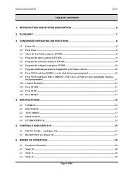
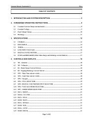
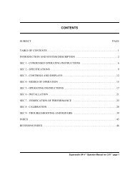
CONTEhITSSUBJECTPAGETABLE OF CO}ITB{TS.INTRODUCTI ONSEC 1 - THEORY OF OPERATION AND CIRCUIT DESCRIPTIONSEC 2 - I/ERIFICATION OF PBFOR},IANCESEC 3 - CALIBRATION.SEC 4 - TROUBLESHOOTING AI{D RBAIRSSEC 5 INSTALLATION.41 51I2327SEC 6 - CIRCUIT SCHEX.IATICSSEC 7 - BILLS OF HATERIALSSEC 6 INDD(.AND ASSHBLY PICTORIALS313549<strong>Superseder</strong> <strong>II</strong> - Technical Manual, rev 0 - page 1
INTRODUCTI ONThe superseder <strong>II</strong> Battery charger/Analyzer is basicalry aprograhmable consLant currenL source for charging and a constanLcurrent sink for discharge, using scR's with phase choppingfor the charge and a transistor linear road for discharge.The duration of the charge and discharge cycles i\re autonaticallyconLrorled by presettabre digitar Liuers, programuablein hours or minutes (or seconds in the tesL cloct< mode).The charge and discharge cycles are also terminated automaticallyas a function of the battery voltage. A cell selectorprograEs the discharge cuL-off vortage at the equivarenL of1.00 volL/cerr and an overvortage charge cut-off at the equivalentof L.7O VoIts/cell.A monitor circuit verifies proper operation and shuLs offthe insLrumenL if an abnormal condition is detected. Conditionsbeing monitored include current tracking (actual vs programnred)battery overtemperaLure (through an externar prate), reversepolarity, open circuit and discharge road bank overheating.A conLrol switch selects the operating mode, while aseries of indicator Iights ahow the operating status.Two digital Panel meters are used to indicate current flowand battery voltage. Ttre voltmeter can also be selected to measureexternal volLages.page 2 - <strong>Superseder</strong> <strong>II</strong> - Technical Manual, rev 0
FIGl-BLOCKDIAGRAT,Iotlq{ toc j;Tl^ratttTotstEcrtFtErSr tct.ti;117g;yT <strong>II</strong>=ctrcutT ,o^r03(CAIO IACXICELL IELECTOAtfATus tx0tcAIors! ,.4'",}'i!<strong>Superseder</strong> <strong>II</strong> - Technicel ltlanual , rev 0 - page 3,-.
sEcl- CIRCUIT DESCRIPTION AND THEORY OF OPERATION1.1 THEORY( ReferOFtoOPERATION, POWER CIRCUITSthe Power Circuit Schematic)1.1.1 Charge:In the supersedei <strong>II</strong>, charge is controrled by chopping ofthe furl wave rectified DC using scR's as power srritchingelements.cRl and cR2 form one harf of a full wave bridge, withSCR1 and SCR2 forning the other half of the bridge.The scR's gate turn-on signar originates in comparatoru11 in Lhe contror board, which is in turn emprified by e3 inthe Pover board. control switch sw203 connects the turn-onsignal to the SCR gates in the charge positions.charge moduration is achieved by varying the conductionangle of the SCR's from about g0 degrees (maximum currenL) toabout 180 degrees (zero current).The actua.l conducLion a.ngle is a function of the progremmedcurrent, battery voltage and Iine voltage. conducLion ingleincreases a.s: programned current increases, battery voltageincreases and as Iine voltage decreases.Current feedback is obtained from SHUNT4O1 and it is feddirectly to the digitat ammeter 1.1201 and to the Control circuitboard via the Control Switch.t.L.2 Discharge:A bank of 24 power transistors forms an electronic loadthat enabres the superseder <strong>II</strong> to discharge the battery undertesL at e conetanL rate. 01*Power transistore Q3 to fi provide a path to ground where[he discharge currenL is controLled by the signal originatingin amplifier ug in the contror board, and subsequentry anplifiedby control trensistors e1 and e2.Discharge modulation is achieved by varying the anpli-Lude of the signar appried to the base of el wnicrr in turnvaries the conduction of Qz which ultimately varies [he conductionof the rest of the transistor bank.Control switch St{203 connects the drive signal from theconLrol board Lo the gate of e1 in the discharg,ecurrentlositions.feedback is obtained from sHUNr4ol and it isapplied to the digital ammeter M2O1 and to the Control circuitboard (same as for charge but sith the polariLy of the shuntsignal reversed to the Control boa.rd) .page 4 - <strong>Superseder</strong> <strong>II</strong> - Technical Menual, rev O
1.2 THEORY OF OPERATION, CONTROL CIRCUITS:(Refer to the circuit board, .nd other circuit sehenatics),..2.L CONTROL CIRCUIT BOARD.rhe contror circuitdigitalBoardcircuitshouses thetoprinciparconirol theanarog andof thetot Enesfi;;seder.currer current W the operating urodea) Analog section:Anplifier ul0yieldingamplifies (x100)an outputthe signalLr _100nV/A from tthe ie,--i0A _ _1.000shunt,contror switctr reverses t|" p?raria, volts) . Theing from charge (posiLive i, the input input)whentoswitch_to maintain ii""rra.ge (negative input),!n" :iI" "utp.rtpotaritV.-'capacitors crz andted during 'cr9.in,;;;;i"Lhe^chargethe short purses genera_Trinpot "p"i"tionpioJ,.r"i..rg R37 is-useia smoothedto ed5ust -io, DC output.yith zero current flow (reset an outputstate).of 0.000v,Anplifier ugandbuffersapplies-itsthe progiaunea outpuL tocurrentintegra[oi-uginput signalruuued via R36, with theviaoutputR24,ifwhere it is,?re programned "ipfifierU10.tiometercurrentRzol for Hain :npu!-;;;""r originates in poten_ping/Discharge crrrr"nt and pofentioueiercurrent. Trre potentioi"t".s nioz for Top_with a dial range fromare s000 toturn devices0'000 to s.o0o.rolt",500, with a vort"g" range ofThe outputs of u10 "oi"""ponding and to 00.0 to so.,-i.p".ug aie -elso thev are fed to the t{onitori:::lt;}:"""onp"t.afor actuar ro prosrammed currenrThe sum .of. -thesi'gnalouputs of ug, which andis theu1o generatesdifference betweenthe erroractuar varue of thethe programnedcurrent..ft;-iit"g""to"and thetere the error rigner amprifend applies ies anditftI conparatorir_Tl:e output of the intllrato"-isu11.about -1.SV at iUout +0.SSVuedium cuii"nts.at reset andis used to calibrate rhe low end (1Anp)",rr""rft:::;":'uof rhecomparatorviaul1 receivessignara.ramp (synchronizedrDL and e1), exienaing withfror-."""Iythe lineof about 3 volts, 'vhich i"'"orp"red0 vori" to a peaktor ug' Tree:"=:.rr,with.isthe output of Integra_scR's on) "-"q.r"r"wavewhen the posiiir"that goesrampt;;-tIu.nrngsignaltheintegrator signar, ind- -i"r"ins cro"""" ii" ,r"g"tivethe line zerorowcrossing).inti I the ra.Dp resets (atL_-- - - - - -;;;;; ;; ; - i i -: -;; ;;; ; ;; ; -;;;; ; - ;;; - ; -: -;;; - ; -
The conduction angle then, increases or decreases es afunction of the error signar, to maintain the programmed chargerate. In the discharge mode the ouput of Integrator ug isapplied Lo the discharge bank of transistors via R30. In [hiscase, the output signar goes more negative to increase theconduction (and thus the currenL) of the transistors.Anplifier u8 receives its input through Anatog Gates tJzA,lrTB and u7D, vhich deternine Lhe source of the programnedcurrent value. uzD swi tches the !,IAIN currenL, as programmed bypotentiometer R201, UZA swiLches the TOPPING/DISCHARGE current,as programned by potentiometer R202 and uzB switches a smallnegative voltage (-50nv) during reset to force the Integratorto go positive.R46 and C25 form a simple integrator to prowide a slowrise (soft start) of the current, frou. zero to Lhe programedvalue in a matter of 3 to 5 seconds.R47 and CR4 rapidly discharge C25, when the charge ordischarge are interrupted by the pressing of the RESET button,to insure e sofL start.vorLage regulator ulz is used to generate a precision+10.000 voltt reference for the Control and Monitor circuitboards.b) Digilal section:The digiLal circuitry of the Control board together withthe Control Svitch and the Timer board, estabish and controlthe operating nodes of the <strong>Superseder</strong>.The l'{ain and ropping/Discharge modes are control ledLhrough the flip-frop formed by gates u3c and u3B. Their outputs,through gates u6A and uoB and inverters usB and usAenable analog gaLe u7D for Hain current or uzA for Topping/Dischargecurrent. Gate U3A enables analog gate U7B and(throughdisablesinverter uSc) gates u6A and u6B in the Reset state.The outpuLs of inverters uSB and uSA are arso applied toamplifers in the Porer board to turn on Lhe l{ain and Topping orDischrrge indicators in the ConLrol PaneI.Ttre mode flip-ftop is starLed in the ilain position (by theReset switch), or it may be sterted in the Topping/DischargeposiLion if Lhe signal TIE is ron (having selected the singleRate or Discharge mode).If started in the Hain posiLion (having selected the TwoRate mode), the flip-flop wirl change state when the Timerboard generates the TIC signar, which ocurs when Lhe elapsedtine eguals the time progrenned for }lain charge.The flip-frop formed by gates u2A and uzB is used Loterminate tha operation of the superseder, fron signals originatingin the Timer or Monitor circuit boards.page 6 - <strong>Superseder</strong> <strong>II</strong> - Technical Manual, rev O
The flip-flop is started in iLsstate,off positionarrd itin the Resetis set to the cycre End positionthe aignal froubytheeither TTc,Timer that i" generatedprogrammed attimerthe endoFof theby cycle Endrhena[ thetheHonitor board generatedbattery being discharged reachesTtre output1.00v/cerl.of the flip-frop (EAL) ie applied to the powercircuit board to turn on Lrre L""p",light*ndthatlire findicatesrashing greenthe conptetion of a cycle.operetion of the supersedergeneratedis harted by theby theHordHonitorsignar,circuit board (whencondition)itordetectsbya faurtLhe power Fair comparator,the powerLhat swiLches whensigar lzv"A" falrs below gs[referencedof its normar varue, asby zener diode zR1 vhichbackedis12v"B"fed bysuppry.the batteryNot_e: 1zv'8,, supplcircuitsiesexcept.i rthetheclockdigitarLED readout.If halLed by the power Fail Detector,reauEe operationthe supersederuponwirlnormar return ofthethe powercontrol switchtirovidedhasthatnot been disturbed).I.2.2 TI},IER CIRCUIT BOARD.ftre Tiner Circuit Board consists of the Tine Counters andcomparator circuits reguired to program the elapsed operatingtimes of the <strong>Superseder</strong>.counter ul receives the-tining signar rDL (rinezero crossing, frequency,L20 pps for 60Hz andtheioo ppsPoner board,for 50whichHz), frourdivides it downE1-E2-E3to zHz. Ttre jumperrerves to programatdivision by s50Hz oror 660Hzforrespectivily.operation atAn additilnar output of 60 pps isalso generated (pin 3).Flip-flop vz divides t!:vhile ?H, signal dorrn to rHz (1pps)counter g? divides by 60 to gen"i"tecounterse lppnu6,signal.u3A and ulBtivelydiviaetouy 60,achievei-0 and 10arespec-finat output of HH,ftlt or xM:ss depending onthe setting of gyitch 'SW1In the Normal position(theof Swl the Tiuer functions as HH:HMdisplay at the clock boa.rd advancescount perat [he rate of oneminute). In the Fast position,H!'t:ss (Lhe the Tiner funtions asdispray at the croix board advancesone count perat thesecond).rate ofIn the Test position, the crock60is advancedcounts perat the ratesecond.ofThe Rese! "ignaroriginates atrowtheduringcontrortimerboard.ope'ation (powerIt is.,'airureincruded),shuLdownand it isconditionhigh vhen the urritTheis inHLD.(hord)the resetsignalstate.is generatedIt isby therow duringcontrornormalboard.operation and goes high during a power<strong>Superseder</strong> <strong>II</strong> - Technical Manual, rev 0 _ paEe z
failure, vhen a ualfunction is detec[ed or at the end of acycIe.Note: HLD stops the Timer (and clock) but does not arterthe display. Reset returns al I corrnters Lo zero.Comparator UA receives input f rom the }lain Time selectorswiLch (T1) and conpares iL to the output of counter U3A (hoursor minuLes). comparators u7 and u4 receive inputs from theTotar Tiue selecLor switch (T2> and compare i[ Lo Lhe outputsof counters u3A and u3B (hours and tens of hours, or minutesand Lens of ninutes).outputs TIC and rrc (positive pulses of .s sec duration),are sent Lo the Control board to signal that }lain and Totalelapsed timeE equal the programmed values.Diodes CRz, CR3, CR4 and CRS and transistor e1 form a gateto generate a TTC signal when the elapsed tine equals 60 (hoursor ui.nuLes). Total Tine svitch settings greater than 60 are notrecognized by the circuiL and wi<strong>II</strong> produce inconsistent elapsedt imes .T.2.3 CLOCK CIRCUIT BOARD.The clock/Display circuiL Board consisLs of the TimeCounler and LED readouts to display the elapsed time.Counters US and OZ divide the Clock signal ( 1ppn, lpps or60pps) by 60 and 100 respeclivery, to achieve a display formatof FIH:H!,I or Ml,l:ss in accordance to the clock speed setting atthe Timer board.Decoder-drivers Ul, U3, U4 and U6 interprete the BeDencoded signal frorn the counters and convert then into outputsfor the 7 eegment LED readouts.Ttre outpuL section of the decoder-drivers is powered from1zv"A", while the rest of the circuiLs are powered by 12v"8".In the event of a pover fairure (whire the unit is running),the 12v"A" wirl drop out, thus turning the LED readouts off,but 12"8" (which is battery backed-up), wilr maintain Lhe coun-Ler positions until power is restored.The Reset signar originates at the contror board. It islow during crock operation (including during a power failureshuLdovn condition), and it is high when the uniL is in reset.Transistor Q1 drives the colon LED's at the rate of oneflash per second, using the lpps signal from the Tiner board asinpuL.page 6 - <strong>Superseder</strong> <strong>II</strong> - Technical l,lanual, rev 0
T.2.4 UONITOR CIRCUIT BOARD.The Monitor Circuit Board conaists ofcircuits that detect certein abnormaliLiesthe <strong>Superseder</strong>.various comparatorin the operation ofa,) Battery volLage section.Anplifier u11 generates an output which isvortege (Note: -.1 x batteryTtre superseder <strong>II</strong> erectronics floats on thebalLef voltage). Input divider R6g and R6s attenuateterythe bat-volLage while R39 calibrates the ettenuation.Anprifier ulz buffers the cell serectoroutput (positive) and sums itsvith Lhe output of U11 (negative) through R64and R40 respectively. Comparator VL? switchei positive when thebattery vorLage is ress than Lhe input from the cerlandserector,it switches low shen the battery voltage exceedes Lhefrominpuicerl serector. R3B calibrates the sritching point (duringcharge).The celr eerector is excited with lovgeneratingduring charge,a signar of .lv/cell, but the summing ratio of R6a,R38 end R40 esteblish e switching point equival-ntcell forto t.?ovt-overvoltage cut-off.In the discharge positions, the cell selectorisexcitationdropped to 5.88V to yield an equivarenL of 1.00v/celrdischarge cut-off.forThe output switching of conparator ulz resurts inEnd (discharge) cycteor overvortage Halfunction (charge), dependingon the state of the Discharge Enable signal (pres-nt at pin glJand originating in the Control Switch).If Discharge Enabte is high (discharge), gate uzA wirr beenabled (and gate uzB disabred), and a high t; rowrttransitionu17 wirl generate a high output at gatesignaruzc vhichthe controrwillboard to terminate [rr" cycle. If Ful rDischarge is selected, v?e,thusis disabled,eliminating cycle eEffiffie to uiTGif vortage.If Discharge Enable is low (charge), gate uzB will be enabled(and gate u7A disabled), and B io, t; high transition atu17 wirl generate a low output at gate vzB silnalingvoltageen over-malfunct ion condition.Transistor Q3 and diodes CRg and CR10 momentaritygatesdisableu7A and u7B at power-on to eriminate false outputs. Ttrebase of 03 is conLrolled by a power-on reset network formed bycR6, cR7, R41, R42 and c3. Th,; voltage at ca,zet'osLartingatrronpower-of f , wi I I remai.r row f or several secrrnds thusholding all circuits aL reset.Ttre output of amplifier Ul1 is also applied tocomparatorsvariousthat monitor battery voltage.<strong>Superseder</strong> <strong>II</strong> - Technical Ha.nual, rev 0 - page g
Comparator U10D is an absolute overvoltage detector, whichwilr yierd a row output if the battery voltage exceeds 8sv. ItsouLput is oR'ed with the output of gate u7B to generate a vorta,gemalfunction indication.comparator u15 is set Lo yield e low oupuL for reversepolarity battery voltages greater than .3SV.comparator u10c is set to yierd a high output at batteryvortages greater than 36v. Its output is AND'ed with the outputof comparaLor u10A, which is set to yield a high output forbattery currents greater than 20A. The outputs of boLh corBparatorswirl then rise only for battery voltages greater than 36vand currents greaLer than 2OA.The conparators establish one of the inputs of gate u1c.The other input is Discharge Enabre. If both inputs are high,the low output of gate UlC through transistor Q2 will generatea current fault condition in the discharge mode. Ttre low outputis arso appried, through diode cRl1, Lo the output of Dischargeserector potentioueter R2o2, thus riniling the dischargecurrenL to 2oA, Lo protect the discharge transistors fromexcessive power dissipation.comparaLor u10B is set to yield a high output at batteryvortagee less than 2v. Gate ulB wirl receive this signar andalso Discharge Enable, to disEble under-current monitoringduring dicharge aL battery voltages under ZV.A lov output at gate ulB is applied to gate ulD, used asan inverLer, which turns f,ransistor e1 oD, urtimaLely disabringconparator U8.b) Current uonitoring section.Comparators UB and Ug foru a window cornparator where theoutputs are oR'ed and wirl go low, signaring e currenL faurt ifthe charge (or discharge) current differs from the programrnedcurrent by more than one anp (over or under).Res i s tor e R?7 and R26 suB the Programrned Cur rent ( pos i t ivevarue) and Actual Current (negative value) signals from thecontrol board. Ttre difference signal forms one input of thecomparators. The oLher input is e resistive divider generating+.05V and -.05V, for the undercurrent and overcurrent comparatorsrespectively.If the currenL difference exceedes one amp (over or under)then the suuned signal difference will exceed 50nV (negative orpositive), thus triggering the conparators.c) Heatsink overheat monitoring section.Comparators U13 and U14 are set to sense an overheating ofthe discharge heaL sinks and to signal a.n Overheat Malfunctioncondition by generat:.ng a low ouLput.page 10 - <strong>Superseder</strong> I I - Technical Manual, rev 0
The signar input for each of the conparators is generatedby r resistive divider formed by a precision resistor (R44 andR47) connected to +10v and a precision (30K a[ zs deg c) thermistorconnected to ground. The neferenee input is e divider,formed by R45 and R48, set to produce +1.45v. If the surfacetenperature at eiLher heatsink reaches 90 deg c, then the inputsignal wilI equal the re&6nce, thus generating a low output atthe comparators.d) BaLtery overtenp monitoring secLion.Comps,rators U3 ( 4 sect ions ) and UB ( 4 sections) uonitorthe signal originating in the Temp-plate. Ttre outputs of U3vi<strong>II</strong> go low if Lhe surface tempere.ture of Lhe Temp-plateexceedes 45 deg c, signaring a BaLLery overtemp marfunction.The ouLputs of UO will go low if a'ny of the Temp-plate thermistors,or its connections (cable disconnected) are open,signaring an abnormarity by turning on the red overtemp tightthrough transistor Q5.The signal input for each of the comparators is generatedby a resistive divider formed by a precision resistor connectedto +10V (R18, R19, R20 and R21), and a precision thermistor(30K at 25 deg C) connected to ground.Ttre reference input for the U3 comparators is a dividerforued by R14 and R16, set to generate 6.2QV for [he sensing ofan overheated battery. The reference input for the u6 comparatorsis a divider forued by R17 and R15, set to generate g.1Vfor the sensing of open circuited inputs (open circuil =10.00v) .e) Output signaling eection.The signals from the various uonitoring circuits areapplied to the flip-flop, forued by gates U2A and UzB, and tothe four section Iatch U5.Ttre flip-flop sets vith any of the faults and generates aIow output, through driver U4B and tesL/run switch 5911, toaignal a Fault to the Power board (a.larm) and to signal Hold tothe ConLroI board, through diode CRZ.The flip-flop is reset by the Reset button in the Controlswitch, through CR7 and R41, and by the loss of 12V"A", a.s aresult of a power failure.Note: any faulL signals present while the unit is in thereset state wi<strong>II</strong> signal via the alarm, even thoughthe flip-flop will not latch and Lhe indi.cators witlnot Iight up, except for the Reverse Polarity fault,that will drive the indicator directly and themultiple latch and Hold, Lhrough diodes CR3, CR4and CRS.<strong>Superseder</strong> <strong>II</strong> - Technical l,lanual, rev 0 - page 11
capacitor c3 hords initiarly the reset inpu[ row (as itcharges through R41 and R42) to reject falee fault conditionsthaL nay be genera.ted while the porer and control circuitsstabilize aL porer-on.A<strong>II</strong> signals from the faulL monitoring comparators are alsointegrated by Rc circuits, to firter any false (brief), faurtcondition that may occur during power turn-on, start-up or apower Iine transient. Transistor Q4 is used specificarly tohold off any possibte response Lo a current fault during thestarL-up process. Ttre signal for 04 is derived from the emitterof Q3 which is in turn driven by the Reset Rc network of R41,R42 and c3, with an effective tiue deray of severar seconds.The stages of the nultiple ratch are set by Lhe correspondinginpuLs derived frou the comparaLors, Ttre outputs are connectedto lamp drivers that turn on the fronL panel faurt indicators.A lHz strobe signal received from the power board isused to turn on and off Lhe ouputs of the multipre latch, topulsate (blink) the fault indicators.1 .2.5 POWM CIRCUIT BOARDThe Power Circuit Board provides various regulated voltagesneeded Lhroughout Lhe conLrol circuits of the <strong>Superseder</strong>.Bridge rectifier cRz, resistors Rg and R10 and capacitorc3 and cs foru a basic positive and negative raw dc suppry ofabout 20 to 25V.voltage regurators u4 and u3 regulate this input voltageand produce +- 15v respectivery. ca.pacitor E cz and c6 f irterthe output and diodes cRg, cR13, cR14 and cRB protect theregulators in case of input shorts or output connection topower rails of opposite polarity.Diodes cR1 and cR4 produce a furr wave unfiltered DCsignar (about 16v avg) used as a source for the tining pulseTDL, Lhe Lzv regulator, to Lrickre charge an externar z.zvnickel-cadmium battery, and Lo suppry the scR trigger amprifier.Ttre tining signal rDL is a positive pulse of 1-2ms producedby the turn off of transistor ez at the zero crossing ofthe rectified full wave.The recLified furl wave is passed through diode cR3 andresistor R11 and firtered by capacitor c4 to produce about 20vas input for u5, the 12v regurator. capacitor c1o firters theoutput vhile diodes CR10 and CRl2 protect the regulator againstinput shorts or output connection Lo opposite porarity powerraiIs.Diodes cRs and cRo sum and isorate the ouLpuL from thebattery with the output of the 12v regulator to generaLe the12v"8" power rail. In case of a power ( rine) f ai lure the lzv"B,,page LZ - <strong>Superseder</strong> I I - Technical llanual, rev O
output wirr drop from 11.4v as suppried by the regurator, toabout 7.8v as supplied by the battery, to maintain the tiningand control circuits.Diode cR11 isolates and outputs 1zv',A,, (non batterybacked), to supply 11.4v Lo the displays in the crock board the Power f ai I cornparator in the Control board ."r,iTransistor Q3 receives via resistor R1s [he trigger inputsignal, a low pulse originating in the control board, andamplifies it into e positive purse applied to lhe scR gatesthrough resistor R16.Power driwers UlE and U1C receive the MAIN and TOPpING/DISCHARGE status signals from the Control board and output thecorresponding drive signals to the HAIN indicator direcLly andto the TOPPING or DISCHARGE indicators through the Controlswitch.oscirlator uz generates a LHz square wave which is appliedto the cycle end alarm and indicator circuit and to ttre Monitorboard to produce beeping of the ararm and flashing of the indicelLors .Transistor Ql receives via CR17 the EAL (cycle end) signalgenerated at the Control board and amplifies it to drive theinput of pover driver U1B.when EAL is present, BS a high signal, the base of e1 willbe purled high by resistor Rlg, thus driving the emitter outputhigh, but the square wave output of oscirlator l)2, throughdiode cR19, wirr produce a corresponding square wave at Lheemiter output of Q1 and at the output of u1B, thus beeping thealarm (through diode cRls) and flashing the cycre end/Resetindicator (through CRz0) .If the Fault input is pulled row (normatly high) by theilonitor board, the beeper is turned on continuousry throughdiode cR16, and the base of e1 is putled low, through diodecR18, thus turning off Lhe cycre end indicaLor circuit.1.2.6 CONTROL SWITCH.The control switch provides arl signals and switchingpertinent Lo the specific operating modes of the superseder.RESET: low signar appried to the control and Monitorboards, to stop and reset the operation of the instrument.TIE: high signar to the contror board to enable the tworate mode.scR GATES: connects scR gates to the output of the drivertransistor in the Power board in the two charge rositions. Theyare otherwise grounded to common.DISCHARGE EIABLE: high signal appried to the Honitor boardin the discharge positions.<strong>Superseder</strong> <strong>II</strong> - Technical Manual, rev 0 - page 13
FULL DISCHARGE: row signal applied to the !,ronitor board toenable full discharge.RESET INDICATOR: turns on (grounds) the Reset indicator inthe Reset position.BATTERY: disconnects the back-up battery in the ResetpositionTOPPING/DISCHARGE INDICATOR: routes the indicator dr iversignar (lov) from the Power board to either the Topping or DischargeindicaLors.DISCHARGE TRANSISTOR: connects the base of control transistorS1 to the drive ouput in the Control board. Otherwise itis shorted to its emitter.CELL sELEcroR: drops the excitation to Lhe cell selectorto switch from 1..7vlcerr in charge to 1.0v/cerl in discharge.SHUNT AMPLIFIffi: reverses the potariLy of the shunt signarsgoing to the amplifier in the contror board when changingfrom charge to dischargeADJUSTME<strong>II</strong>TS: the Control Switch circuit board also housesthe adjustments for the current selecLor potentiometers and LheCeIl selector (see section on Calibration).L.2.7 DPM CIRCUIT.The DP!,i circuit provides alI signar routing and attenuationfor the operation of the Digitar Anmeter and the DigitalVoltmeLer.a) A!,<strong>II</strong>.{ETER: the digitar ammeLer is a g-L t z digit Dpt{ witha furl scale of 199.9 nVDC. It is connected directry to a shunLwith an output of 1mv/A, thus reading direclly in Amperes( 199.9A) .b) VOLTMETER: the digital volLmeter is e g-Lt2 digit DpMvith a furr scare of 1.999 vDc. It is connected to the batteryunder test or to the externar jacks via the DpM serectorswitch. The swiLch selecLs also Lhe LHI t10K voltage divider f ora full scale of 19.99 V or svitches an additional(zKlLOKtattenuatorfor a fu<strong>II</strong> scale of 199.9 V.page L4 - <strong>Superseder</strong> I I - Technical Manual, rev 0!i!i
SEC 2 - VERIFICATION OF PBFORMANCETtre <strong>Superseder</strong> <strong>II</strong> has been designed, manufactured and testedto give thousands of hours of troubre free operation, butif you find that your unit is not performing prolerly (or asexpected) 'please refer first to the operating instructions forre-assurance that proper procedures are being forrowed.If it is determined then, that your superseder <strong>II</strong> is malfunctioning,prease refer to the verification of performance,calibration and troubleshooting eections which wilt show youhow to use the various builL-in tesL features to determine orapproximate the nature of Lhe problem.NOTE: In the forlowing Lests nake no connection to a batteryunress specifically indicated. Always start from resetand always reset et the conclusion of e test.Refer to the Lroubreshooting section in case any deviationsare observed.2.I . I VISUAL VBIFICATION.Turn power on. Resetlcycle end (green) light must be onand the digitar pa.nel meters and elapsed time dispraymust read zero (colon must be off).2. L . 2 TIT.{ER VERIFICATION.set main and topping charge current selectors to zero.set both Lime selectors to zero. set the switch in thetimer board to the test (center) position.NOTE: current and voltage readings must remain at zeroduring the following tests.sLarl the trnit by depressing the two rate charge selector.UniL will go immediately into cycle end. ReseL.set the totar time to 01 and start. unit wilt start inmain charge end iumediatery transfer to Lopping, goinginto cycle end after one second. Reset.Set Lhe ma.in time to L , total time to OZ and start.unit wirl start in the uain mode, transfer to toppingafter one second and go into cycle end after two seconds.Reset.Repeat the above tests, each time advancing the main andtotal tine selectors as follows: ZlO4, 4tOg, g/Og, g/10,9120,9140 and 9/60.<strong>Superseder</strong> <strong>II</strong> - Technical Manualr rev O - page 15
2 . L .3 BATTERY OVERTE{P CUT-OFF.Set current selectors to zero.Set the timer speed switch in the normal ( right)position.Set tine selectors to LlOl and cell selector to ZO.Connect the battery cable Lo the unit but make no batteryor teup-plate connections. The red overtenp lightwill be on.Connect one 16.5 K-OHM (L%\ resistor between pins D and Band one each 50 K-OI{}i (lX) resistors between pins D andC, D and E, and D and H. Ttre red light will turn off andan audible elarru will be heard.Start in either of Lhe charge modes. Unit wi<strong>II</strong> start andiqmediately go into overtemp fault (red Iight flashingand alarm on) . Reset.Repeat the previous tesL by rotating the 16.S K-OHMresistor in a<strong>II</strong> four positions.Repeat the first test using four 1a K-oHt{ ( 1u ) resis-Lors. Unit must not show overtemp fault.2.L.42.1.52.L.6VOLTAGE FAULT TEST.Reuove battery cabIe.set current selectors (both) to 010. set time selectorsto LIOL. Set cell selector to 20.start in either of [he charge modes. unit wilt start andthe output. voltage vill sIowly rise. Unit will stop,indicating a voltage fault. Reset.REVERSE POLARITY TEST.Connect the battery cable, rith the single cell adaptor,to one cell vith the polarity reversed. unit wirl immediatelyshow a faulL through the ararm and Lhe volLagefault Iight.OVERVOLTAGE CUT.OFE"set currenL seleetors to zero and time selectors to 1/ot.Set celI selector to 20.connect the battery cable to an adjustable vortage source( lov current power supply), set to approxiuately 30 VOLTSand start the unit in either charge mode.slowry increase the voltage. unit wilr stop and indicatea voltage fault aL 34V +- .5V. Reset.page 16 - <strong>Superseder</strong> <strong>II</strong> - Technical }lanual, rev 0
2.T.7 DISCI{ARGE VOLTAGE CUT-OFI"Set current selectors to zero and time selectors to 1/012.1.82.1.9SeL cell selector Lo 20Connect the batterycurrent power supply),the unit in the auto diSlowly decrease the volat 20V +- .3V. Reset.iaUfe to a volLage source ( Iowset Lo approximately 24V and startscharge rnode (blue).tage. Unit will go into cycle endFULL DISCHARGE.set current selectors to zero. set time selectors to1/01. Set celI selector to ZO.slart the unit in the furl discharge mode (red). unitwilr run. Increase [he discharge current selector to anyvalue above 1Al,fP (010). Unit will continue to run.SwiLch Lo auto discharge. Unit wi<strong>II</strong> go to cycle end.ReseL.CURREhIT TRACKING.connect cabre to battery. set tine selectors to 1/01 andcelI selector consistent with the battery.set the main charge current selector to 2s Al{ps (zso) andthe [opping charge to 1 AMP (010).start Lhe uniL in the Lvo rate mode. current vilr rise to25.0A +- .35A.switch to the single rate uode. current vilr drop to 1.0A+- .24. Reset.Repeat this test for other high and low sett ings.Repeat aleo for the discharge mode.NOTE: In diseharge, the readings may be lover by .1A Lo.2A.2. 1.10 CURREI{T FAULT TEST.Connect cable to battery. Set tine selectors to 1 l0t andce<strong>II</strong> selector consistent vith battery.Set the main charge current to zero and Lhe toppingcurrent selector to 2A (020).Start the unit in the topping node (yellow button).Adjust the low current caribrate trimpot in the controrboard until the current approaches 3A. srowly increaseit untir a current faurt is achieved. It wilr occur at3A +-.2aReset and return the trimpoL (down s-10 turns) Lo aboutits original setting before the next test.SLart the unit in the topping mode. Adjust the lowcurrent carib'ate trimpot untir it approaches 1A. slowlydecrease the current until a current faurt is obLained.It witl occur at 1A +- .2A.Reset and return the low current calibrate to its properca I ibrat i on .<strong>Superseder</strong> <strong>II</strong> - Technical Hanual, rev 0page Lz
SEC 3 - CALIBRATIONNorE: The superseder <strong>II</strong> musL be verified/caribratedat least once every lZ months, or earlier ifdeviation from performance is observed.Perform adjustments onry shen changing parts and conponentsthat require recalibration or when the procedure forverification of performance indicates that the unit is essentiallyfunctioning but it is out of adjustmenL.3.1 DIGITAL PANEL METERS..CAUTION! 115vAC is present on the Dplrl circuit board.Digital panel neters are adjusted by Eeans of a nurtiturnLrimming potenLiometer (trinpot) located in the right handcorner of Lhe meter, vhich is exposed by the removal of thefront bezel/red filter window.3,1.1 "CURREI\[[ " ![E[ER.This oeLer has a full scale of 199.9 nilrivolLs to read a50 Al,lP shunt with an output of one mirrivort per AHp.verify and calibrate using a low voltage source of so to100 nirrivolts (battery or poyer suppry and suitabrealtenuaLor) oF, by ueasuring the vortage at the shuntwith a digitar vortmeter in the .zA (zoonA) scale.Also, check against an exLernal amneter having anaccuracy of .257 or better.3.L.2 "VOLTAGE" MEIER.This meter has a furl scale of 1. ggg volts, but an attenuatoron the DPI.{ board conwerLs it to a full scare of19.99 or 199.9 vorts, as serected by the DpM selectorswi tch.Calibrate (meter triupot) using a voltage source between10 and 20 volLs in the "EXfIERNAL zOV" position.calibration of the z00v scale is acomplished by adjustingthe trimpot located on the DPM circuit board. Calibrateby using a source between 50 and 10OV with the DPtrl Selectorin the "DCIERNAL 200V,, position.page 18 - <strong>Superseder</strong> I I - Technical Manual, rev 0
FIG 2 - DPM AND ST<strong>II</strong>TCH CIRCUIT BOARD ADJUSTI,IEX.ITS*.aR'?oov scALECAL IBRATER3CURRENT SELECTORPOTENTIO}TETEFSCALTBRATERIBATTERY VOLTAGECUT-OFFCALIBRATESUITCHSuperreder <strong>II</strong> - Technical Hanual, rev 0 - page 19
3.2 CIRCUIT BOARD ADJUST},TE}.ITS AND CALIBRATION.WARNINGI The ground of the electronice circuitry floats on Lhebettery voltage. }lake no connections between the electronicsground and the battery or chassis ground.3 .2 . T DPI,I ( DIG ITAL PANEL HETERS CONNECTI ON BOARD) .see 3.L.2 and fig 2.3.2.2 SWITCH (see f ig 2>..,!.ffi - CURREI.IT CALIBRATE...' This trimpot is adjusted for e reading of 3.500 vorts atthe wiper of the Hain Charge Current Potentiometer set toread 350.Ttre voltage reading at E+ (outputence amplifier) musL rea.d .lV/Aoperation) . r'ie: prograrnming of 25A nust yield_-.. R2 - CELL CALIBRATE.i/ r rhis trinpot is used to set the Discharge cur-oFF at s0.0\ yelts with the ce<strong>II</strong> selector at S0.'r*+&@**--$iiSiAt This rast slep requires that the trtoNIToR circuitboard be prewiously calibrated.3 .2.3 CLOCK/DISPLAY.None.3 .2 .4 TIHER.Jumper to select 50 or 60 HZ operation.3.2.5 CONTROL (see fig 3).of the current refer-+- l%, +-.01V (during2.5V +-.035NOTE: Use the conmon leads of Cl1, Clf andreference for voltage Deasurenents.R29 10 VOLT ADJUST}.{EI.IT.This trimpoL is adjusted for a reading of+-.005V at E7.C16 as ground10.000 voltsR37 - AI'IPLIFIER ZERO.This trimpot is adjusted+-.005V at E3.for a reading of0.000 voltsR28 - LOW CURRET{T CALIBRATE.This trimpot is adjusted for a' reading ofcurrent digiLal panel meter, with thecurrenL poLentiometer seL for 1 AMp (010).1 .0 A!,lP aL thetopping chargepage 20 - <strong>Superseder</strong> I I - Technical llanual, rev 0
Frc 3 - gg[r.RgF AtrD IgsISgn crRcurr BoARD ADTUSTME]rTSRZSHI€H CALIBRATER29l0v AoJusTR2aLOY CALIBRATEI taIEqe7IOV TEST POINTi37I tl^i{PLIFtER ZEROEIFTERTEST ?OINTCONTROL6ROUNOTEST POINTR3;EATTERY OVERVOLTAGECALIBRATE( CHARGE )R39BATTERY YOLTAGECAL I ERATETTERY VOLTAGEAIrPL IF I ER ITEsr PorNry'iroNtToFOROUNDTEST POINT<strong>Superseder</strong> <strong>II</strong> - Technical llanual, rev 0 - page ZL
R25 - I{IGH CURRENT CALIBRATEThis trimpot is adjusted for a reading ofthe current3s.0 AHps atdigital panel meLer, withpotentioueterthe uain currentset for 35 Al,IpS (3S0).The vortage reading et E3 (shunt auprifier output) mustcorreapond to the charge (or discharge) currenL asfollows: voltege at E3 = -.1V/A +-12 +-. O1V. ie: ZSAequals -2.5V, +- .03SVNorE: high current calibration must be preceded by thezero and lov current calib..ations.3 .2 .6 <strong>II</strong>ONITOR ( see f ig 3 ) .R39 - BATTERY VOLTAGEThis trimpot is edjusted for a reading atpondE1toto corres-one tenth of the battery voltage presentinputat theterminals.NorE: The reading wirl be negative. If the batteryage isvort-25 volts, iL vilt read Z.S0O volts.R38 - OVERVOLTAGEThis trinpot is adjusted for a charge cut-off vortage of51.0 voIte, rith the ce<strong>II</strong> se_lec.tor-a! 3O !.o.r gaV ai-iOi.NorE: use the co'mon reads of c?,'cg, ca and clo asground reference for voltage measureuents.3.2.7 POT'ERThere are no adjustments in the power circuit board, buLthe forrowing vortages musL be measured at the card edgeconnection fingers (bottom), using a standard digitilvoI tueter .PIN s r VbLTAGE11-13 * 36VAC (+- 2V nominal, line dependent).t2 r 12"B,, (11.4V +-.6V)14 * COMI'ION15 * +15V (+15.0V +-.75>.16 * -15V (-15.0V +-.75r.17 x gV Battery (3.SV +-1V).18 * 16V (t7Y +- 1V).2L * Tiuing pulse (1.2V +- .1V).22 * 12V,'A.' (11.4 +- .6V).page 22 - <strong>Superseder</strong> I I - Technical Manual, rev 0
SEC 4 - TROUBLESHOOTING A},TD REPAIRS4. 1 IBOUBLESHOOTING.The following are hintr rnd directions to help you rocatethe nost probable ceuses of deviation of p"iflrr"rr"" asestablished in the procedures of section 3.4.1.1 UNIT CHARGES BUT DOES NOT DISCHARGE.Open discharge current liniter. Signal to base of controltransisLor t1 interrupted.4.L.2 UNIT CHARGES PROPERLY ONE BATTERY BUT CANNOT CHARGE T[f,OBATTERIES AT HIGH RATES.Low Iine voltage.4.1.3 UNIT GOES <strong>II</strong>..lltO VOLTAGE FAULT IMI,IEDIATELY oR SHORTLYAFTER STARTING Up (charge uode).Open link or one or roore cells developing a high voltage.Check that the nunber of cells relecled agrees wiLh Lhebat tery.4.1.4 UNIT DISCHARGES BUT IdILL NOT CHARGE.Defective Power or Control circuit boards. Signal to SCRates interrupted.UNIT CHARGES LOW CURREI.IT (BELOT{ 10 A},TPS ) PROPERLYUT HUI.{S NOTICEABLY AT HIGHER CURRE.ITS.one of tlie scR' s i s inoperat ive . t{easure the cur renttheatred output lead of each scR with a clamp-on amnetercapabre of reading pursati.ng DC, or measure as f orloyrs:Disconnect the gate of one of the scR's (any one), andrepeat tne test. Having disconnected the g"t" of thedefective device vilr have no ef f ect. Discirrr,""tinggetetheof the good scR ritl resulL in no current frow.11. 1 .6 UNIT STARTS IN THE DISCHARGE I,IODE BUT THERE IS NO CURRENTFLOtir. CURRENT FAULT FOLLOWS .ogen discharge current limiter, or faulty connectionthetocontror tra.nsistors, or def ective contror transistors.4.1.7 UNIT STARTS IN TT{E DISCHARGE I,IODE BUT GOES INTO CYCLE EI{DIM},IEDI ATELY .Battery not properly connected. open rink. open cable.Number of celIs aelected not consistent with thl4.1.8baLtery.THE DISCHARGE CURRE TT L<strong>II</strong>.<strong>II</strong>TER OPE}IS THE Ho}.{EhIT A BATTERYI S CONNECTED TO T}IE CHARGER .Shorted discharge trensistors(s) .4.L.9 BURNED RESISTOR(S) IN THE DISCHARGE HEATSINK(S) .Transistor(s) shorLed. often due to wrong discharge4.1.10fuse.UNIT TfILL NOT CHARGE OR DISCHARGE. NO C'RRqYT FAULT.Faulty current selector potentiometer(s). 1ov noLreaching Lhe control switch circuit board. tfiring<strong>Superseder</strong> <strong>II</strong> - Technical Hanual, rev O - page 23
interruption between the Control Switch circuiL boardand the potentioneters. FauIty Control circuit board.4.1.11 CYCLE END INDICATOR AND TTMER DISPLAY DO NOT TURN ON.Open fuse to electronics card rack or problems with thePower circuit board or the transformer feeding it.4.L.12 DIGITAL VOLTMETER REGISTERS A VOLTAGE (36 VOLTSAPPROX<strong>II</strong>.TATELY) WITH THE UNIT IN RESET AND NO BATTERYCONNECTED.One or both SCR'S shorted. Do not connecL a batteryunder this conditionl ! !To test, disconnect one of the SCR's, l:oth output lead(red) and the gate lead (blulgry) and measure accrosswith an ohmueter.4.L.13 CURREI.IT TRACKING IS OFF BY A SI,IALL CONSTANT A},IOUNT.Anplifier zero or low current calibrate out of adjustment(CONTROL board).{.1.14 CURREI-IT TRACKING IS OFT. BY A SMALL A},IOUMT WHICH INCREA-SES AS THE PROGRA<strong>II</strong>{ED VALUE IS INCREASEDHigh current calibrate out of adjustment (CONTROLboard).4.1.15 TI{E CLOCK RUNS 20U FASTm (OR SLOWER).Incorrect Iina freguency selecLion on the TIl,tER circuitboard.4.1.16 T}IE UNIT STARTS BUT D(HIBITS CURREhIT FAULT AFTB SOMET<strong>II</strong>IE (f rom a f ew seconds to a few ninutes).a) Current tracking is of f , exceeding 1 AtlP: Ver if yConLrol board calibration. See 3.2.5 and 3.2.2.b) Current tracking is proper: Verify that Lhe shuntanplifier in the Control board reads properly. See3.2.5 and 3.2.2.4.1. 17 FAULT LIG}IT(S) ON AND NO AUDIBLE ALARI,I. UNIT RUNSNORMALLY.a) Switch in the Honitor board is set in lhe testposition.b) If the svitch is in the correct position (run), turnpower off and back on Lo clear the condition andresume operation rithout resetting.c) Defective swiLch.4.1.18 DIGITAL METERS DO NOT TURN ON.Open fuse to digital panel meters.page 24 - Supereeder I I - Technical Manual, rev 0
4.2 FINDING A SHORTED DISCHARGE TRANSISTOR.since all diacha.rge transistors ere vired in pararsinglelel, ashorted transistor rilr short the entire Lanx.necessaryIt isthen, to test each trensistor individuatry intoorderfind the defecLive one.The procedure that foltows will allow the findingshortedof thetransistor wiLhout reguiring removal and test ingeach deviceofindividually.4.2.1 EQUIPT{E}<strong>II</strong> REOUIRED. (see fig 4>1) Voltmeter (digital prefered).2) Battery, Z4V.3) Lamp, 24V (lanp must draw at least .S A).4.2.2 PROCEDUFIE.1) TURN UNIT OFF,. DISCONNECT IT FROM TI{E WALL OUTLET.2, connect the ranp in place of the discharge currentIimiLer (see fig 4).3) Connect the unit to the battery.4) If the lamp illuminates, it indicates that there is ashort in the discharge circuit, generated by one ormore shorted transistors.5) l{easure the voltage across the individual .zz oHMemitter resistors.A non zero reading, approximately .lV for a lampdrawing .5A, indicates currenL frow due to a transisterwith a collector to emitLer short.NorE: A rrcn zero reading on arI emitter resistors-approximately .02V for a lamp drawing . SA_indicates a different failure uode ( correctorto base short; refer to step ?>.6) -Removeany shorLed transistors ana repeat steps 4 and5 untir a no short reading is obtained.tiveReptacldevicesdefec-only with types HJlso23, MJlsb04, uJ15o02or 2N6031.7, If all transistors appear to be shorted (ALLresistorsemitterreading a vortage), Lhen, one or Dore havefailed rith a collector to base short, causing theremainder of the transistors to turn on. It witr thenbe necessary to check each transistor individually.This cen be greatry faciritated by searching io. azero reading. TIeis will indicate the shorted device.8) when repracing transistors, add heat sinking compoundand nake sure that the base and emitter pin"properry ln the socket contacts. Torque the "rrg"g" screwsproperly to insure a good thermal transfer.NorE: If repracing any of the contror Lransistors (e1and Q2), note that they are Dounted with a micainsulator.<strong>Superseder</strong> <strong>II</strong> - Technieal Manual, r€lv O - page Zs
FIG4- MEASURING FOR SHORTED TRANSISTORSVOLTMETER. ?2 OHM RES I STORTRANS I STORHEATS I NK?'VI .IA LAMP24V BATTERYALTERNATE EXCITATIONpage 26 - <strong>Superseder</strong> <strong>II</strong> - Technical Ha.nual, rev 0
SECTION 5INSTALLATION5.188{CH SPACE.The superseder <strong>II</strong> system occupies lg" x lr" (49.3 cB x 4g.zcm) of tabre top spece for the charger e.nd 10" x zs" (zs cEX 63.5 cm) for Lhe tenp-plate.Arlor also at least 6" (15.2 cm) of separation from theralr and adjacent equipment, in order Lo maintain properair f low (VITAL!).NorE: operation in dusty or otherwise "dirty" air environmentswill severery reduce the cooring capacity ofthe fens and lead to premature failure.5.2 LINE VOLTAGE.connect the unit to a walr receptacle NEMA 6-30R, 23ov (or208V) wiLh a 30 A!,lP capaciLy.NorE: operation of this unit with e "soft" line or with aIine voltage 10I above or below the nominal 2OAlZSOvAc will resurt in erratic operation and may arsolead to equipment damage if Iarge volLage surgesoccur.5.3 CHANGING LINE VOLTAGE.Ttre superseder I I is normalry wired f or z30v operation.rtre forlowing directions are for changes to 20gv or 11sv.(Refer to figures 5 and 6)5.3. 1 208VAC operation:1) shift.reft red jumper from position 3 to position z.2t shift whiLe lead (from the breaker) from position 6to position 5.3) shift right red junper from position lz to position11.4> shifL shite lead (from the breaker) from position 1sto position 14.NOTE: Line current vi<strong>II</strong> increase by about 10%.5.3.2 11SVAC operation:1) Remove red jumpers (2).2, InsteI first black jumper frou position 1 toposition 43) Instarr first white jumper from position 4 toposition 64, Instalr second black jumper from position 10 toposition 13.<strong>Superseder</strong> <strong>II</strong> - Technical Manual, rev O - page ZZ
5) Instelr second vhite juuper frou position 72 toposition 1S.6) Remove the 2A0V 30A line cord.7, Install a tlSV ZOA li;; cord.NOTE: Line current virldoubre. Linit charging currentto ZOApage2A - <strong>Superseder</strong> I I - Technical Ma.nual , rev 0
FIG 5 - POWER WIRING, 208 I23OVk\.Ni$I I 5V ELECTRONICSTRANSFORT-IER It_-__I36vtFUSEI./tA sBI l5V\N8LHEREAT(ER /lOAqT.Tl* Gt-PYT/IY4I]li fVHT<strong>II</strong>I( 208 )(208)REOnlgv FANlt<strong>II</strong>V }IETERS{_F-FUSE -,/.A SBTRANSFORI{ER 2l36VlA_ Z 4 6 7 a I to t2 t2 t4 L^-^/-l,lJ Irs Lilsi!l . $t {L$l dtL_(208)- /inREO<strong>II</strong>I la ,l 5 6 7 a s /o IZ LJ tl k7r{-a{LJ]IiillIL L HIt Nr@l, L1NE CORO230V 30AHEIiIA 5-3OFSuperaeder <strong>II</strong> - Technicel Hanual, rev 18 - page 29
FIG 6POWM WIRING, 115VBREAKER'OAELECTRONI CSI I 5V HETERSTRANSFOR}.IER IFUSEI /'A SBFUSEl./aA 68,TRANSFORHER 2-----l35vI\\s.wasLINE CORDllSv 30Ap&ge 30 - <strong>Superseder</strong> <strong>II</strong> - Technical Hanual, rev lB