Superseder II
Superseder II
Superseder II
You also want an ePaper? Increase the reach of your titles
YUMPU automatically turns print PDFs into web optimized ePapers that Google loves.
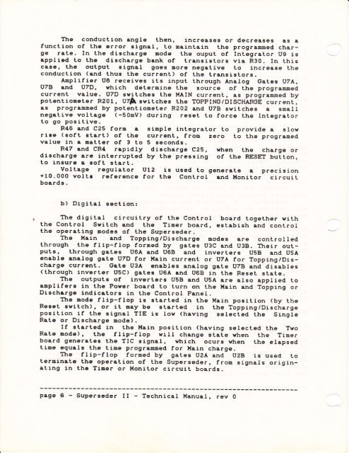
The conduction angle then, increases or decreases es afunction of the error signar, to maintain the programmed chargerate. In the discharge mode the ouput of Integrator ug isapplied Lo the discharge bank of transistors via R30. In [hiscase, the output signar goes more negative to increase theconduction (and thus the currenL) of the transistors.Anplifier u8 receives its input through Anatog Gates tJzA,lrTB and u7D, vhich deternine Lhe source of the programnedcurrent value. uzD swi tches the !,IAIN currenL, as programmed bypotentiometer R201, UZA swiLches the TOPPING/DISCHARGE current,as programned by potentiometer R202 and uzB switches a smallnegative voltage (-50nv) during reset to force the Integratorto go positive.R46 and C25 form a simple integrator to prowide a slowrise (soft start) of the current, frou. zero to Lhe programedvalue in a matter of 3 to 5 seconds.R47 and CR4 rapidly discharge C25, when the charge ordischarge are interrupted by the pressing of the RESET button,to insure e sofL start.vorLage regulator ulz is used to generate a precision+10.000 voltt reference for the Control and Monitor circuitboards.b) Digilal section:The digiLal circuitry of the Control board together withthe Control Svitch and the Timer board, estabish and controlthe operating nodes of the <strong>Superseder</strong>.The l'{ain and ropping/Discharge modes are control ledLhrough the flip-frop formed by gates u3c and u3B. Their outputs,through gates u6A and uoB and inverters usB and usAenable analog gaLe u7D for Hain current or uzA for Topping/Dischargecurrent. Gate U3A enables analog gate U7B and(throughdisablesinverter uSc) gates u6A and u6B in the Reset state.The outpuLs of inverters uSB and uSA are arso applied toamplifers in the Porer board to turn on Lhe l{ain and Topping orDischrrge indicators in the ConLrol PaneI.Ttre mode flip-ftop is starLed in the ilain position (by theReset switch), or it may be sterted in the Topping/DischargeposiLion if Lhe signal TIE is ron (having selected the singleRate or Discharge mode).If started in the Hain posiLion (having selected the TwoRate mode), the flip-flop wirl change state when the Timerboard generates the TIC signar, which ocurs when Lhe elapsedtine eguals the time progrenned for }lain charge.The flip-frop formed by gates u2A and uzB is used Loterminate tha operation of the superseder, fron signals originatingin the Timer or Monitor circuit boards.page 6 - <strong>Superseder</strong> <strong>II</strong> - Technical Manual, rev O


