
You also want an ePaper? Increase the reach of your titles
YUMPU automatically turns print PDFs into web optimized ePapers that Google loves.
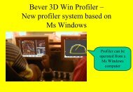
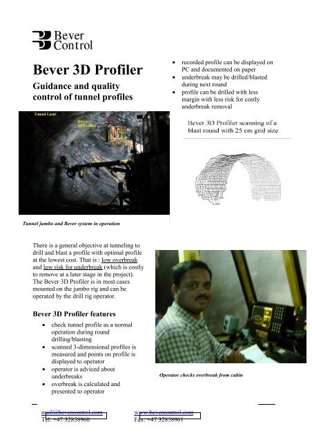
<strong>Bever</strong> <strong>3D</strong> <strong>Profiler</strong>Guidance and qualitycontrol of tunnel profiles• recorded profile can be displayed onPC and documented on paper• underbreak may be drilled/blastedduring next round• profile can be drilled with lessmargin with less risk for costlyunderbreak removalTunnel jumbo and <strong>Bever</strong> system in operationThere is a general objective at tunneling todrill and blast a profile with optimal profileat the lowest cost. That is : low overbreakand low risk for underbreak (which is costlyto remove at a later stage in the project).The <strong>Bever</strong> <strong>3D</strong> <strong>Profiler</strong> is in most casesmounted on the jumbo rig and can beoperated by the drill rig operator.<strong>Bever</strong> <strong>3D</strong> <strong>Profiler</strong> features• check tunnel profile as a normaloperation during rounddrilling/blasting• scanned 3-dimensional profiles ismeasured and points on profile isdisplayed to operator• operator is adviced aboutunderbreaks• overbreak is calculated andpresented to operatorOperator checks overbreak from cabinmail@bevercontrol.comwww.bevercontrol.comTel: +47 32858960 Fax: +47 32858961
• reduced need for surveying work,later profiling• scanning may be done whiledrilling next round• operator on rig can operate theprofiler without expert assistanceA laser distance measuring unit is mountedon a fixture and is operated by twoprogrammable axis. The profiler isnormally placed on the console in front ofthe operator cabin on the tunnelling jumbo.Remote control of profiler from the cabinor other convenient location.Mode of operationSingle point recording using joystickpointerThe operator will position by remotecontrol of the profiler. The joystick ismounted in a portable unit with cableconnection to the rig. A red pointinglaser shows the actual point to recordand a pushbutton gives single pointrecording. On the display in the cabinthe operator can observe actualdeviation from reference profile.measured points is shown, and the datais displayed online for the operator. Hecan immediately evaluate the results,additionally calculatedoverbreak/underbreak is displayed.All measured data are saved on thememory card. The data is available withfully defined coordinates in text files thatmay be processed by standard PCprograms.<strong>Bever</strong> <strong>Control</strong> delivers anapplication for evaluation of results ongraphic display and printouts.Setup : Navigation beforescanning or single pointmeasurementThe jumbo is placed for normal drilling.The tunnel laser is used for alignement ofthe profiler. Two points on the tunnel laseris recorded by pointing with the profiler.The peg number identifying the tunnelcoordinates is entered by the operator foran aiming target placed in the laser line.The scanned area can be defined assections of 1-6 metres and the grid size canalso be set. Typical distance on grid size is25 cm.3-dimensional scanning of a definedtunnel sectionThe operator can select a tunnel sectionfor scanning. A typical example will beto check one blast of 5 metres and agrid of measuring points spaced at 25cm. On the display the cloud ofpage 2 of 4
Operators displayThe reference profile is displayed on thescreen with actual measured points plottedon the screen. The driller can thusimmediately conclude whether the pointsare inside or outside the reference profiles,and also the distance is given. Calculatedoverbreak/underbreak is displayed as wellas maximum distances from referenceprofile. The scanned data are stored onmemory card ready for later processing ona desktop PC.Screen on the rig shows overbrake directto the operator.page 3 of 4
Desktop PC processingScanned data are transferred to officecomputers by means of a memory card. Onthe PC the profile and actual logged datamay be graphically displayed and aselected section documented on paper.AccuracyAccuracy of a measurement on a smoothsurface perpendicular to the scanningdirection will be 2-3 cm atpreset scanning speed. Dueto variation of rock surfaceover the actual footprintand angle of attack, theaccuracy will vary. It isrequired that the navigationis accurate and that the rigdoes not move during themeasuring period.Import and export of coordinates from survey tools iseasyOverbreak statistics is calculatedGunnersbraten 2P.O.box 20N-3421 LierskogenNorwayTel: +47 32858960Fax: +47 32858961www.bevercontrol.commail@bevercontrol.compage 4 of 4