history of walkover locating technology - Digital Control Inc.
history of walkover locating technology - Digital Control Inc.
history of walkover locating technology - Digital Control Inc.

Create successful ePaper yourself
Turn your PDF publications into a flip-book with our unique Google optimized e-Paper software.
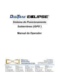
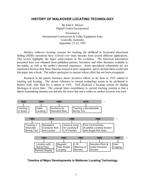
HISTORY OF WALKOVER LOCATING TECHNOLOGYBy John E. Mercer<strong>Digital</strong> <strong>Control</strong> <strong>Inc</strong>orporatedPresented atInternational Construction & Utility Equipment ExpoLouisville, KentuckySeptember 23-25, 1997Modern <strong>walkover</strong> <strong>locating</strong> systems for tracking the drillhead in horizontal directionaldrilling (HDD) operations have evolved over many decades from several different applications.This review highlights the major achievements in this evolution. The historical informationpresented here was obtained from published patents, brochures and other literature available tothe public, as well as the author’s personal experience. Some specialized refinements are notmentioned because their basic function existed in prior equipment, and to include them would turnthis paper into a book. The author apologizes to anyone whose effort has not been recognized.Research in the patent literature shows inventive efforts as far back as 1933 related totracking and <strong>locating</strong>. The closest reference to current <strong>technology</strong> seems to be attributed toRobert Neff, who filed for a patent in 1955. Neff disclosed a <strong>locating</strong> system for findingblockages in sewer lines. The concept bares resemblance to current tracking systems in that adipole transmitting antenna was fed into the sewer line and a <strong>walkover</strong> surface receiver was used1955 1965 1968 1970Trackingin SewerCableLocatingGuidance forSteerable MoleTracking a NonsteerableBoring Tool19841985 1986 1988Tracking aSteerableBoring ToolNavigationComputer Builtinto LocatorAntenna Arrayfor Locating &L / R PositionFirst CommerciallyAvailable Locating Systemwith Single-Roll Index19911992 1993 1995 1997Locators withRoll & PitchRemote DisplayMagneticField ShapeLocatingL / RSteering onRemoteSensitive Pitch &Cable-PoweredSondesDataLoggingTimeline <strong>of</strong> Major Developments in Walkover Locating Technology1
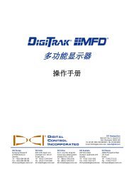
1955 Neff Electronic Locator Systemto locate the antenna. The dipole antenna was oriented perpendicular to the surface rather thanparallel, as in current locator transmitters. The receiver used a simple volume control andheadphones to direct the operator. This system guided the operator to a position above theantenna, but could not determine depth. Because high-power transistors were not available atthat time, vacuum tubes were used for both the receiver and thetransmitter. The confined space available for the downholedevice precluded having the transmitter there. Instead thetransmitter was above ground and only the antenna went downhole.This allowed the transmitter to be connected to 110-voltpower.In 1965 C. A. Young <strong>of</strong> Bell Laboratories wrote an articlein the Bell Laboratories Record describing a cable locatorthat used the ratio <strong>of</strong> signal strengths measured by two horizontalantennas at two heights <strong>of</strong>f the ground to determine thedepth <strong>of</strong> a cable. This method assumes that the field strengthvariation <strong>of</strong> the magnetic field emanating from the cable isknown. For long, straight cables the signal strength variation isinversely proportional to the distance from the cable, i.e.,double the distance, halve the signal strength. If the cable hasbends or terminates close to the locator, then the signal strengthrelation is not known. Most current boring tool locators usethis twin horizontal antenna arrangement to determine depth.In the late 1960’s Bell Telephone Laboratories built aguided impact tool or mole. Although the guidance system didnot fall into the category <strong>of</strong> a <strong>walkover</strong> tracking system, it wasthe first time that a small-diameter boring device was outfittedwith guidance. A patent filed in 1968 by James Coyne <strong>of</strong> Bell1965 Bell LaboratoriesDepthometer2
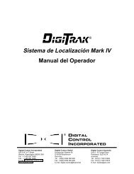
Labs describes a complex arrangement<strong>of</strong> receiving and transmittingantennas that provided asteering signal used to control themole. The system was never commercializedand no one picked upthe effort to develop a steerablesystem at that time. Interest intracking nonsteerable tools didcontinue, however.By the late 1960’s the transistorreigned in electronics. ItThe Goldak Co. Transistorized DipoleTransmitter (1970 McCullough and Ladine)could handle the speed and the power demanded by transmitters. In 1970 Lester McCullough andDuane Ladine <strong>of</strong> The Goldak Co. developed a transistorized dipole transmitter that was pottedinto a section <strong>of</strong> an unguided boring tool. One or two receivers were used to find the nulls in themagnetic field in front <strong>of</strong> and behind the boring tool. McCullough and Ladine state that thedistance between the two nulls can be related to the depth by calibrating. This procedure used theshape <strong>of</strong> the magnetic field to determine depth. They did not provide a description <strong>of</strong> how to findthe nulls except to move the receiver longitudinally along the transmitter axis (assuming that itwas known). Their description was one <strong>of</strong> thefirst documented references to the use <strong>of</strong> themagnetic field shape for gathering <strong>locating</strong>information.Toward the end <strong>of</strong> the 1970’s the ElectricPower Research Institute (EPRI) became awarethat the practical life <strong>of</strong> buried distribution cablewas about 20 years. Reviewing cable placementrecords made EPRI aware <strong>of</strong> a real problem theywere about to face. Many <strong>of</strong> the locations wherecables had been placed were now developed, andreplacement would be a major disruption. Consequentlythey sponsored development <strong>of</strong> tools toreplace electric power cables without disruption.As an outcome <strong>of</strong> this sponsorship FlowMole ®Corporation was formed (now UTILX). In 1984the author headed an intense development <strong>of</strong>directional drilling tools resulting in the production<strong>of</strong> the GuideDril System. Key to the developmentwas the ability to locate the boring toolhead. By this time cable <strong>locating</strong> tools had beenwell established, so direct use <strong>of</strong> a cable locator(Metrotech ® 810) in the GuideDril System wasattempted. A signal was induced on the drill pipe,and the cable locator was used in the normalMetrotech ® 810Radio Frequency Line Tracer3
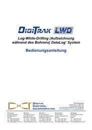
fashion. The locator failed to perform because the drilled hole was not straight and the drill pipeended at the tool head being located. Attention was then turned to developing a dipole transmitterthat could be fitted into the boring tool head. This proved to be the solution, although thelocator had to be rotated 90 degrees relative to how it was designed to be used in order to capturethe dipole flux lines. Also a table had to be constructed to relate the depth readings from theMetrotech 810, which was calibrated for cables, to the depth <strong>of</strong> the dipole transmitter in thedrillhead.By this time, the mid 80’s, microprocessors werecapable <strong>of</strong> performing complex calculations, and theirlow cost made them attractive to incorporate intoelectronic designs. In 1985 a navigational computerwas added to the locators used by UTILX. The operatorscould type in the located coordinates <strong>of</strong> thedrillhead, and the computer would return a steeringcommand. However, the operators did not like theextra work involved, so the computer was removedfrom the locator. Still, the requirements <strong>of</strong> <strong>locating</strong> aboring tool were sufficiently different from <strong>locating</strong> acable, so the development <strong>of</strong> a new locator wasrequired. In 1986 the author and Albert Chau developedthe FlowCator ® . This locator used an array <strong>of</strong>antennas to determine the position <strong>of</strong> the tool head.Arrows directed the operator fore and aft along theintended path. Adjacent to the tool head the operatorwould press a button and the FlowCator would takemeasurements from the different antennas in the arrayand compute the depth and lateral <strong>of</strong>fset from theintended path. The instrument also had the capability<strong>of</strong> providing a steering command, but that feature wasnever used because the operators felt it added toomuch time to the <strong>locating</strong> process.FlowMole ® FlowCator ®Several problems were encountered in <strong>locating</strong> with <strong>walkover</strong> systems during their developmentto this stage. The first was the ghost or phantom locate points. These points representpeaks in the signal strength fore and aft <strong>of</strong> the tool head. They are produced by the receiver’santenna arrangement. Although these ghost peaks are not as strong as the peak over the head,they can and still do fool many operators. The result is the operator can mislocate the tool headand the computed depth is not correct. Even the FlowCator with its arrows for directing theoperator could be fooled unless it was in the vicinity <strong>of</strong> the tool head.The second challenge <strong>of</strong> <strong>walkover</strong> systems was in training operators to control the depth <strong>of</strong>the drillhead. Left/right steering was easy by comparison, because the operator could mark thelocate points on the ground surface and see trends from these marks. Depth, on the other hand,had no such cues, and novice operators would <strong>of</strong>ten find themselves pushing in drill pipe with adepth oscillation that resulted in the tool breaking the surface. A knowledge <strong>of</strong> the pitch orienta-4
tion <strong>of</strong> the head would have eliminated this problem. UTILX discussed pitch sensing in several <strong>of</strong>its patents and had some prototype guidance systems with this feature, but had not implementedpitch sensing in its <strong>walkover</strong> locators.The third challenge was finding a tool after an extended bore where <strong>locating</strong> was impossible,such as under a busy highway or a river crossing. No systematic means to locate adipole transmitter could be found that would work with the detection arrangement <strong>of</strong> theFlowCator or any cable locator system. If the direction <strong>of</strong> the boring tool is not known as well asits position, then the location effort becomes monumental. For example, an 8-foot by 8-foot (2.4-m by 2.4-m) platform was built by UTILX for use in training operators to locate a lost tool head,and with a transmitter placed under the platform at an unknown location and orientation, a welltrainedoperator would take several minutes to find it.After just a couple <strong>of</strong> years <strong>of</strong> operation a fourth challenge arose. By this time it was becomingroutine to drill horizontally over several hundred feet. The drill pipe was keyed so thatthe steering surface <strong>of</strong> the tool head was fixed to a drill chuck index. As the drilling distanceincreased, the drill pipe would twist and the tool head orientation would no longer correspond tothe chuck index. The operators compensated for this by noting the signal strength as the drillrotated slowly. Since the transmitter window in the drillhead was oriented upward when the drillwas in the 12:00 position, the peak signal strength was at 12:00. This gave the operators arudimentary means to correct for drill string wrap-up, assuming the wrap-up would not changewith rotation.Until 1988 there were no HDD tracking systems commercially available, since UTILX’sequipment was not for sale. In that year Radiodetection ® <strong>of</strong>fered a system (RD300) that was aderivative <strong>of</strong> a sewer <strong>locating</strong> system they had developed. The transmitter (sonde) introduced inthis system solved one <strong>of</strong> the challenges recognized by UTILX’s experience, that <strong>of</strong> accountingfor drill string wrap-up. Radiodetection solvedthis problem by incorporating a gravitationalswitch in the sonde. Normally the sonde wouldsend a pulsed signal, but in the 12:00 positionthe signal would be ON continuously. Thisprovided a more accurate means to correct forthe wrap-up, assuming that the wrap-up wouldnot change as the drill string was rotated past12:00 to the desired steering orientation.In 1989 Peter Flowerdew at Radiodetectionfiled a patent for a locator that couldprovide both roll and pitch orientation. Thesystem was based on two rotating and onenonrotating magnetic fields. This system did notprovide an absolute orientation but rather arelative one that depended on where the operatorwas standing relative to the drillhead andwould change as the <strong>locating</strong> receiver wasRadiodetection ® RD300 Locator5
moved. The ability to get roll information would eliminate thewrap-up problem, and the ability to determine pitch wouldgreatly reduce the operator training. Although the intent was onthe mark, the implementation was not practical, so it did notbecome commercialized.In 1991 competition grew with new manufacturers enteringthe industry. Several significant advancements were madeto <strong>walkover</strong> tracking systems. Both Ditch Witch ® and <strong>Digital</strong><strong>Control</strong> introduced new systems. The Ditch Witch Subsite system was a combined cable locator and tracking system. Thissystem was based on digital signal processing and could operateon several frequencies. It also included a gravitational rollsensor that provided an absolute roll orientation, whichcompletely eliminated wrap-up steering errors. At the same time<strong>Digital</strong> <strong>Control</strong> introduced the DigiTrak System. The DigiTrakSystem was designed from the beginning to be a boring toollocator and departed from the conventional cable locator<strong>technology</strong>. It used a pair <strong>of</strong> orthogonal antennas to measure thetotal magnetic field in the plane <strong>of</strong> the locator. This techniqueeliminated one <strong>of</strong> the <strong>locating</strong> challenges mentioned above, thatDitch Witch<strong>of</strong> ghosts. There are no ghosts with this method. Also, the unit® Subsite 80 Rdeparted from the cable locator scheme <strong>of</strong> determining depth.Instead it employed a calibration procedure based on the fact that the transmitter in the drillheadhousing is designed to produce a uniform, constant signal. The depth was displayed continuously,unlike prior systems which required the operator to push a button and wait a few seconds. Whennot over the transmitter, the display showed the approximate slant distance to the tool head. Thecompact design employed internal ultrasonic measurement <strong>of</strong> the locator height above the groundsurface to accommodate operators <strong>of</strong> different heights. This feature additionally providedseparation <strong>of</strong> the locator’s antennas from the ground to greatly reduce the adverse influence <strong>of</strong>rebar in streets.At its introduction, the DigiTrak was the first<strong>walkover</strong> system to display both the roll and pitchorientation <strong>of</strong> the tool head as well as the first toprovide a warning for a weak battery condition in thetransmitter. The pitch orientation covered a range <strong>of</strong>-100% to +100% grade in 1% grade increments andwas not influenced by roll orientation. The roll andpitch orientation for the DigiTrak were based on gravityand therefore independent <strong>of</strong> where the operatorwas standing relative to the tool head. Knowledge <strong>of</strong>the pitch orientation greatly increased the speed <strong>of</strong>drilling since fewer locate points were needed tocontrol depth. Also, this knowledge improveddrilling accuracy particularly on uneven terrain. At<strong>Digital</strong> <strong>Control</strong> DigiTrak Receiver6
its introduction, DigiTrak extended the operating depth to 20 feet⎯almost double that <strong>of</strong> prioravailable systems.In late 1991, Cogent Technology in the U.K., an independent newcomer to the drillingindustry, introduced a roll accessory system for the RD300 that included a new transmitter with aroll sensor and a remote display for the roll orientation. The remote display provided the operatorat the drill rig with a means to orient the tool without continuous feedback from the <strong>locating</strong>operator. At the time there was some controversy as to what effect the remote display might haveon the allocation <strong>of</strong> responsibilities between the two drilling operators and, in turn, what effectthis might have on the efficiency <strong>of</strong> the drilling operation. It turned out to have a positive effectand became an important contribution to the industry.Cogent Technology MoleMonitorIn 1992 <strong>Digital</strong> <strong>Control</strong> introduced new firmware in their locator that allowed for a new <strong>locating</strong>technique. The new technique was based on the magnetic field shape rather than the signalstrength. This technique overcame difficulties associated with <strong>locating</strong> a tool head when both theposition and direction were unknown, as discussed above. For the first time it provided asystematic procedure to accomplish this task. The new technique provided an accurate indication<strong>of</strong> when the operator was over the drillhead as well as additional <strong>locating</strong> points ahead <strong>of</strong> andbehind the tool head. These <strong>locating</strong> guidance points provided a very accurate mechanism forsighting the bore path heading. The technique also provided a way to track the tool while thedrillhead was actually moving, thereby reducing <strong>locating</strong> time. Finally, it allowed the operator tolocate the drillhead from a position <strong>of</strong>f to the side, which is useful when drilling under obstruc-7
tions. Both McLaughlin, marketing the Japanese-built Takachiho locator, and <strong>Digital</strong> <strong>Control</strong>recognized the advantage <strong>of</strong> the remote display to their products and developed remote displaysthat included roll, pitch, battery status, and temperature. <strong>Digital</strong> <strong>Control</strong> also included a left/rightsteering indicator to guide the drillhead when the operator could not physically locate over thetool, such as encountered when crossing under busy streets.<strong>Digital</strong> <strong>Control</strong> DigiTrak Receiver (side & top views) and Remote DisplayAlso in 1992, Metrotech decided to develop a boring tool locator. Although their cablelocator was previously used on the first small-diameter HDD systems, they had not provided alocator calibrated to read dipole transmitterdepth nor did they manufacture atransmitter for a boring tool. Bill Griffithsat Metrotech spearheaded the effort,which involved an alliance with Cogent.The resultant BoreHawk included a remotedisplay and was designed as a lowcostsystem. Unfortunately they encounteredtechnical development problemsalong with the untimely death <strong>of</strong> Bill, andtheir new product sales were halted.Cogent/Metrotech BoreHawk During this period, Albert Chau andthe technical staff at UTILX were alsoimproving their equipment. They extendedthe range <strong>of</strong> the locator system andincorporated many <strong>of</strong> the features mentionedabove, including an indication <strong>of</strong>ghost signal peaks. They also developedan instrument package that incorporatednon-<strong>walkover</strong> guidance. One <strong>of</strong> their innovationswas a means to correct position8
errors in a wireline system using a <strong>walkover</strong> locator. They also started selling some <strong>of</strong> theirequipment overseas, but still refrained from domestic sales.<strong>Inc</strong>reased depth range became an issue with contractors as drill rigs became more powerful,so in 1994 <strong>Digital</strong> <strong>Control</strong> <strong>of</strong>fered a transmitter with a 50-foot (15-m) range. The transmitter isthe same size as their shorter-range model.In 1995 <strong>Digital</strong> <strong>Control</strong> opened up the opportunity to extend the HDD process to sewerlines by producing a transmitter with a 0.1% grade pitch sensitivity. In that same year theyproduced a cabled transmitter (Cable Sonde) that extended the depth capability to over 100 feet(30 m). The single-wire connection provided the power required for the strong transmitter in theCable Sonde and at the same time carried the roll, pitch, and status information back to thedisplay on the operator’s console. This means <strong>of</strong> carrying the information in the wire made itimmune to local interference and also allowed application to some non-<strong>walkover</strong> situations.DigiTrak 4-Cell Magenta Sonde (0.1% Pitch)DigiTrak Green Cable Sonde In 1997 the manufacturers <strong>of</strong> <strong>locating</strong> equipment continued to improve their existingproducts and also introduced new advancements. Radiodetection introduced a new <strong>walkover</strong>locator with left/right steering and an array <strong>of</strong> antennas similar to the FlowCator. BothMcLaughlin and <strong>Digital</strong> <strong>Control</strong> introduced bore logging capability. The McLaughlin MoleMap TM provides a display illustrating the bore hole pr<strong>of</strong>ile including depth. The drilling data canalso be uploaded to a computer for future reference and plotting. The <strong>Digital</strong> <strong>Control</strong> DataLogTMsystem provides left/right path, depth and terrain plots that can be augmented with survey datafor exact drill and terrain elevations. A data processing and plotting package is part <strong>of</strong> thesystem. The DataLog can also be used in conjunction with the remote steering feature or theCable Sonde; a laptop computer can also be used to provide real-time plots <strong>of</strong> the bore, a featureuseful for river crossings.Recently Ditch Witch introduced a new system that is a hybrid <strong>of</strong> a wireline system and a<strong>walkover</strong> system. This new system employs a transmitter in the drill head, similar to aconventional <strong>walkover</strong> system. Besides the usual pitch and roll sensors, the Ditch Witchtransmitter has a magnetometer as well. The signal from the transmitter is picked up by a receiveron the surface. That receiver is only required to be within range but does not need to be directlyover the transmitter. The receiver uses telemetry to send the heading, pitch and roll data back tothe remote unit at the drill. These signals are processed by the remote system to compute aposition in a manner identical to conventional wireline guidance. The use <strong>of</strong> a magnetometerrequires that the downhole tooling in the vicinity <strong>of</strong> the transmitter be nonmagnetic.9
Late in the year <strong>Digital</strong> <strong>Control</strong> introduced a new system that uses 2 or more antenna cellsplaced anywhere in the vicinity <strong>of</strong> the intended drill path. There is a transmitter installed in thedrill head which is identical to the <strong>walkover</strong> system. There is no magnetometer in this system sono special downhole tooling is required. The cells transmit received data from the ingroundtransmitter back to a remote base station at the drill rig which computes the location <strong>of</strong> thetransmitter and plots the bore path. The remote display also shows the intended path andprovides a steering indication for the operator. The system allows the operator to drill past theantenna cells. This is particularly beneficial where access to the surface is not possible. Specificapplications would be embankment stabilization, environmental installations or highway crossingsto name a few.Although the last 2 systems described are not <strong>walkover</strong> systems, many <strong>of</strong> their basics haveevolved from the <strong>walkover</strong> concept. The transmitter sensors and data transmission techniquesdevised for the <strong>walkover</strong> systems are key to the new system developments.In summary, modern HDD tracking systems have evolved from sewer line tracers and cablelocators due in main part to the development <strong>of</strong> the transistor and microprocessor. From 1984,when the first small-diameter, guided drilling tools were developed, until today, the abilities <strong>of</strong>tracking systems have progressed substantially. The first systems would only provide a surfacelocation, a rudimentary heading, and a depth range <strong>of</strong> less than 10 feet (3 m). Current locatorsprovide the roll and pitch orientation, temperature, battery status, accurate heading, warnings foroverheating, remote display <strong>of</strong> data, and even logs <strong>of</strong> the bore path at depths exceeding 140 feet(43 m). Transmitters that once could only run for a few hours can now run for over one week onbatteries. In 1990 there was a clear distinction between the small-diameterMcLaughlin Spot D Tek Mole Map System10
<strong>Digital</strong> <strong>Control</strong> DataLog Systemutility installation equipment and the much more massive river crossing equipment. Today thatdistinction is less clear. In 1990 any bore deeper than 12 feet (3.6 m) required a wireline system,with few exceptions. Today drilling runs deeper than 70 feet (21 m) have been performed withtracking systems using battery-powered transmitters. Runs deeper than 100 feet (30 m) havebeen performed with the same receiving system using a transmitter with power supplied by acable. Locating speed and accuracy have improved at a rapid pace and have allowed the HDDprocess to penetrate new markets because <strong>of</strong> reduced costs and increased capabilities.Although <strong>walkover</strong> locators have almost always been used as autonomous systems, there is now arole for them in other guidance systems. Walkover systems can provide final guidance to wirelinebores to eliminate accumulated errors and complete the bore precisely on target. Future guidancesystems will undoubtedly build upon this <strong>technology</strong> and permit further automation <strong>of</strong> the drillingprocess.<strong>Digital</strong> <strong>Control</strong> <strong>Inc</strong>.TRANSITRAK TM iGPS TMinGround Positioning System11