XL-45/50/55HP (with dual regulators) - Taylor-Wharton
XL-45/50/55HP (with dual regulators) - Taylor-Wharton
XL-45/50/55HP (with dual regulators) - Taylor-Wharton

You also want an ePaper? Increase the reach of your titles
YUMPU automatically turns print PDFs into web optimized ePapers that Google loves.
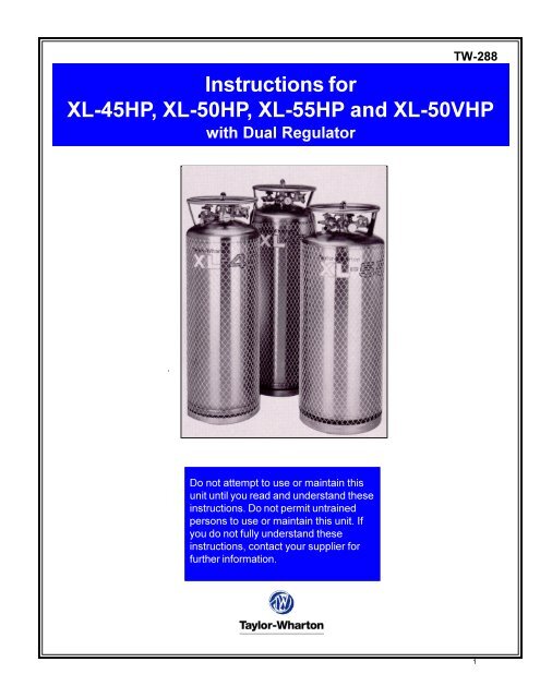
TW-288Instructions for<strong>XL</strong>-<strong>45</strong>HP, <strong>XL</strong>-<strong>50</strong>HP, <strong>XL</strong>-<strong>55HP</strong> and <strong>XL</strong>-<strong>50</strong>VHP<strong>with</strong> Dual RegulatorDo not attempt to use or maintain thisunit until you read and understand theseinstructions. Do not permit untrainedpersons to use or maintain this unit. Ifyou do not fully understand theseinstructions, contact your supplier forfurther information.1
CONTAINERSAFETYNOTE:For detailedinformation on thehandling of cryogenicliquids, refer to theCompressed GasAssociationpublication: P-12“Safe Handling ofCryogenic Liquids”available from theCompressed GasAssociation, Inc. 1235Jefferson DavisHighway, Arlington,VA 22202.Pressure Hazard – The containers covered by this literature may contain pressures up to3<strong>50</strong> psig (24 bar/2413 kPa) for the <strong>XL</strong>-<strong>45</strong>HP/<strong>50</strong>HP/<strong>55HP</strong> and pressures up to <strong>50</strong>0 psig (34bar/3447 kPa) for the <strong>XL</strong>-<strong>50</strong>VHP. Sudden release of this pressure may cause personalinjury by issuing cold gas or liquid, or by expelling parts during servicing. Do not attemptany repairs on these containers until all pressure is released, and the contents have beenallowed to vaporize to ensure no pressure build-up can occur.Extreme Cold-Cover Eyes and Exposed Skin – Accidental contact of the skin or eyes<strong>with</strong> any cryogenic liquid or cold issuing gas may cause a freezing injury similar to frostbite.Protect your eyes and over your skin when handling the container or transferringliquid, or in any instance where the possibility of contact <strong>with</strong> liquid, cold popes and coldgas may exist. Safety goggles or a face shield should be worn when <strong>with</strong>drawing liquid orgas. Long-sleeved clothing and gloves that can be easily removed are recommended forskin protection. Cryogenic liquids are extremely cold and will be at temperatures below -300°F (-184°C) under normal atmospheric pressure.Keep Equipment Well Ventilated – Although some of the gases used in these containersare non-toxic and non-flammable, they can cause asphyxiation in a confined area<strong>with</strong>out adequate ventilation. An atmosphere that does not contain enough oxygen forbreathing will cause dizziness, unconsciousness, or even death. These gasses cannotbe detected by the human senses and will be inhaled normally as if they were air. Ensurethere is adequate ventilation where these gasses are used and store liquid containersoutdoors or only in well ventilated are.Replacement Parts Must be “Cleaned for Oxygen Service” – Some materials, especiallynon-metallic gaskets and seals, can be a combustion hazard if used in oxygen ornitrous oxide service, although they may be acceptable for use <strong>with</strong> other cryogenic liquids.Use only <strong>Taylor</strong>-<strong>Wharton</strong> recommended spare parts, and be certain parts used onoxygen or nitrous oxide equipment marked “cleaned for oxygen service”. For informationon cleaning, consult the Compressed Gas Association (CGA) pamphlet G-4.1, “Cleaningfor Oxygen Service” or equivalent industrial cleaning specifications.Install Relief Valves in Cryogenic Liquid Lines - When installing piping of fill hoseassemblies, make certain a suitable safety relief valve is installed in each section ofplumbing between shut-off valves. Trapped liquefied gas will expand as it warms and mayburst hoses or piping causing damage or personal injury.GENERALINFORMATIONNOTE:The Xl-<strong>50</strong>VHP is notdesigned to store ortransport cryogenicliquid nitrous oxide.The <strong>XL</strong>-<strong>45</strong>HP, <strong>XL</strong>-<strong>50</strong>HP, <strong>XL</strong>-<strong>55HP</strong> and <strong>XL</strong><strong>50</strong>VHP are vacuum insulated, stainless steelcontainers designed to store and transport cryogenic liquid oxygen, nitrogen, argon, carbondioxide, and nitrous oxide. Built to DOT 4L standards, these containers may be usedfor over the road transportation of cryogenic fluids, as well as on-site storage and supplyin a wide range of applications.As rugged, long holding time, self-contained gas supply systems, these cylinders arecapable of providing continuous flow rates of up to 1<strong>50</strong> cfh (3.9 cu.m/h) in carbon dioxideservice, up to 110 cfh (2.9 cu.m/h) in nitrous oxide service, up to 3<strong>50</strong> cfh (9.2 cu.m/h) inother gas services. The <strong>XL</strong>-<strong>45</strong>HP/<strong>50</strong>HP/<strong>55HP</strong> are designed to hold liquid <strong>with</strong> a relief valvesetting of 3<strong>50</strong> psig (24 bar/2413 kPa) and the <strong>XL</strong>-<strong>50</strong>VHP <strong>with</strong> a relief valve setting of <strong>50</strong>0psig (34 bar/3447 kPa), which provides greater holding times than lower pressure cryogeniccontainers2
SPECIFICATIONS<strong>XL</strong>-<strong>45</strong>HP <strong>XL</strong>-<strong>50</strong>HP <strong>XL</strong>-<strong>55HP</strong> <strong>XL</strong>-<strong>50</strong>VHPDimensionsDiameter 20 in. (<strong>50</strong>8 mm) 20 in. (<strong>50</strong>8 mm) 20 in. (<strong>50</strong>8 mm) 20 in. (<strong>50</strong>8 mm)Height 61 3/8 in. (1559 mm) 64 5/8 in. (1641 mm) 69 7/16 in. (1764 mm) 64 3/4 in. (16<strong>45</strong> mm)WeightEmpty (Nominal) 272 lb. (123 kg) 284 lb. (129 kg) 287 lb. (130 kg) 310 lb. (141 kg)Capacity, Gross 176 liters 188 liters 208 liters 188 litersCapacity, Useable Liquid 165 liters 176 liters 198 liters 176 litersWeight of Contents MaximumBased on DOT Rated Service PressureCarbon Dioxide 387 lb. (176 kg) 414 lb. (188 kg) <strong>45</strong>8 (208 kg) 381 (173 kg)Oxygen 360 lb. (163 lb.) 385 lb. (175 kg) 426 (193 kg) 364 lb. (165 kg)Nitrogen 252 lb. (114 kg) 269 lb. (122 kg) 298 lb. (135 kg) 240 lb. (109 kg)Argon 438 lb. (199 kg) 467 lb. (212 kg) 518 lb. (235 kg) 443 lb. (201 kg)Nitrous Oxide 368 lb. (167 kg) 393 lb. (178 kg) 435 lb. (197 kg) N/ANormal Evaporation Rate*(% Capacity per Day)Carbon Dioxide 0.75%0.75% 0.75% 0.80%Oxygen 1.4% 1.2% 1.2% 1.5%Nitrogen 2.2% 2.0% 1.9% 2.2%Argon 1.4% 1.2% 1.2% 1.5%Nitrous Oxide 0.75% 0.75% 0.75% N/AGas Flow Rate @ NTP (STP)**Carbon Dioxide 1<strong>50</strong> cfh (3.9 cu.m/h) 1<strong>50</strong> cfh (3.9 cu.m/h) 1<strong>50</strong> cfh (3.9 cu.m/h) 1<strong>50</strong> cfh (3.9 cu.m/h)Oxygen, Nitrogen, Argon 3<strong>50</strong> cfh (9.2 cu.m/h) 3<strong>50</strong> cfh (9.2 cu.m/h) 3<strong>50</strong> cfh (9.2 cu.m/h) 3<strong>50</strong> cfh (9.2 cu.m/h)Nitrous Oxide 110 cfh (2.9 cu.m/h) 110 cfh (2.9 cu.m/h) 110 cfh (2.9 cu.m/h) N/ARelief Valve Setting 3<strong>50</strong> psig 3<strong>50</strong> psig 3<strong>50</strong> psig <strong>50</strong>0 psig(24 bar/2413 kPa) (24 bar/2413 kPa) (24 bar/2413 kPa) (34 bar/3447 kPa)Inner Container Bursting Disc 525 psig 525 psig 525 psig 7<strong>50</strong> psig(36 bar/3620 kPa) (36 bar/3620 kPa) (36 bar/3620 kPa) (52 bar/5171 kPa)Dual Pressure Building/Economizer Regulator***Pressure Building Setting 300 psig 300 psig 300 psig 400 psig(20.7 bar/2068 kPa) (20.7 bar/2068 kPa) (20.7 bar/2068 kPa) (28 bar/2758 kPa)Economizer Setting 320 psig 320 psig 320 psig 420 psig(22 bar/2206 kPa) (22 bar/2206 kPa) (22 bar/2206 kPa) (29 bar/2896 kPa)Design SpecificationsTC 4LM 4LM N/A N/ADOT 4LM 4LM 4LM 4LMGaseous CapacityBased on DOT Rated Service Pressure@ NTP (STP)Carbon Dioxide 3383 cu.ft. (89 cu.m) 3619 cu.ft. (95cu.m) 4003 cu.ft. (108 cu.m) 3330 cu.ft. (88 cu.m)Oxygen 43<strong>50</strong> cu.ft. (114 cu.m) 4651 cu.ft. (122 cu.m) 5146 cu.ft. (135 cu.m) 4397 cu.ft. (116 cu.m)Nitrogen 3478 cu.ft. (91 cu.m) 3712 cu.ft. (98 cu.m) 4112 cu.ft. (108 cu.m) 3312 cu.ft. (87 cu.m)Argon 4236 cu.ft. (111 cu.m) <strong>45</strong>16 cu.ft. (119 cu.m) <strong>50</strong>12 cu.ft. (132 cu.m) 4285 cu.ft. (113 cu.m)Nitrous Oxide 3211 cu.ft. (84 cu.m) 3429 cu.ft. (90 cu.m) 3796 cu.ft. (106 cu.m) N/ASpecifications are subject to change <strong>with</strong>out notice.* Vented N.E.R. based on Useable Liquid Capacity.** Container pressure at or above factory Dual Pressure Building/Economizer Regulator setting.*** Regulator has a pressure delta of 20 psig (1.4 bar/138 kPa).3
Handling the ContainerThe <strong>XL</strong> Series containers are very rugged liquid cylinders. All cryogenic liquid containershave an inner container and an outer container <strong>with</strong> an insulated vacuum space betweenthem. Any abuse (dents, dropping, tip-over, etc.) can effect the integrity of the containersinsulation system.When fully loaded, the <strong>XL</strong>-<strong>55HP</strong> in argon service will contain up to 518 lb (235 kg) ofproduct. While moving a full container, you may be handling up to 805 lb. (365 kg), andyou should treat the load accordingly. The attachment points provided on the <strong>XL</strong>-<strong>45</strong>HP/<strong>50</strong>HP/<strong>55HP</strong>/<strong>50</strong>VHP will allow you to use a hand truck or a hoist to handle these loadsproperly. Do not attempt to move these cylinders by any other means. While moving thecylinder, the following precautions should be observed:q Never lay the container on its side. Always ship, operate, and store the unit in avertical, or upright position.q When loading or unloading the container from a truck, use a hand truck, lift gate,crane, or parallel loading dock. Never attempt to manually lift the unit.<strong>XL</strong>-<strong>45</strong>HP, <strong>XL</strong>-<strong>50</strong>HP<strong>XL</strong>-<strong>55HP</strong>, <strong>XL</strong>-<strong>50</strong>VHPContainersq To move the container over rough surfaces, or to lift the container, attach an appropriatesling to the lifting points cut into the welded support posts, and use a portablelifting device that will handle the weight of the container and its contents.FREIGHT DAMAGEPRECAUTIONSANY FREIGHT DAMAGECLAIMS ARE YOURRESPONSIBILITY. Cryogenicliquid containers are delivered toyour carrier from <strong>Taylor</strong>-<strong>Wharton</strong>’sdock in new condition. When youreceive our product you mayexpect it to be in that samecondition. For your ownprotection, take time to visuallyinspect each shipment in thepresence of the carrier’s agentbefore you accept delivery. If anydamage is observed, make anappropriate notation on the freightbill. Then ask the driver to signthe notation before you receivethe equipment. You shoulddecline to accept containers thatshow damage which may affectserviceability.4
OPERATIONThe <strong>XL</strong>-<strong>45</strong>HP will store up to 165 liters of product; the <strong>XL</strong> <strong>50</strong>HP/<strong>50</strong>VHP up to 176 liters,and 196 liters for the <strong>XL</strong>-<strong>55HP</strong>. All four cylinders can deliver either liquid or gas. Thefollowing component and circuit descriptions are pertinent to the operation of all the containersand should be read before attempting operation. The components may be identifiedon the Component Location Illustration.<strong>XL</strong>-<strong>45</strong>HP/<strong>50</strong>HP/<strong>55HP</strong>/<strong>50</strong>VHPComponentLocationsInternal Vaporizer – A liquid container for gas service must have an internal heat exchangerthat functions as a gas vaporizer coil to convert liquid product to gas continuouslyduring <strong>with</strong>drawal. The <strong>XL</strong>-<strong>45</strong>HP/<strong>50</strong>HP/<strong>55HP</strong>/<strong>50</strong>VHP utilize an internal heat exchangerthat is inside the vacuum space attached to the container’s outer casing. Itprovides a mean of introducing heat from outside the container’s insulated jacket, tovaporize liquid as gaseous product is <strong>with</strong>drawn. The capacity of this circuit is sufficient tovaporize at flow rates up to 3<strong>50</strong> cfh @ NTP (9.2 cu.m/h @STP). If a greater continuousdemand is put on the vaporizer, an external vaporizer should be added to properly warmthe gas and avoid malfunction, or damage, to gas <strong>regulators</strong>, hoses, and other downstreamcomponents.Pressure Building – A Pressure Building circuit is used to ensure sufficient driving pressureduring high <strong>with</strong>drawal periods. This function is actuated by opening a hand valve thatcreates a path from the liquid in the bottom of the container, through the Pressure BuildingRegulator, to the gas space in the top. When the pressure building valve is open, and thecontainer pressure is below the pressure building regulator setting, liquid taken from the5
inner container is vaporized in a heat exchanger which is insidethe outer casing. The expanding gas is fed into the upper sectionof the container to build pressure. The resulting process willdrive either the liquid or gas delivery system.Pressure Building is not normally required unless container pressuredrops below the gas output pressure desired. If, for example,the container pressure gauge reads 2<strong>50</strong> psig (17.2 bar/1724 kPa), and your gas pressure requirement is 270 psig (19bar/1860 kPa), and the pressure building valve may be openedto build container pressure to 300 psig (20.7 bar/2068 kPa).Economizer – An economizer circuit <strong>with</strong>draws gas preferentiallyfrom the head space over the liquid container – gas thatwould otherwise be lost to venting. Excess pressure in the headspace of the container is relieved by allowing gas to flow fromthis area directly to the USE valve outlets while gas is being<strong>with</strong>drawn from the container; yet normal operating pressure ispreserved to ensure uninterrupted product delivery. The economizeris automatic and requires no operator attention.<strong>XL</strong>-<strong>45</strong>HP/<strong>XL</strong>-<strong>50</strong>HP/<strong>XL</strong>-<strong>55HP</strong> and <strong>XL</strong>-<strong>50</strong>VHP FlowDiagramNOTE:The economizer andpressure buildingfunctions are controlledby a single <strong>dual</strong> actionregulator. The pressuredelta between thepressure buildingsetpoint and theeconomizer setpoint isapproximately 20 psig(1.4 bar/138 kPa). Thisdelta cannot be altered.WARNING:Never use the DualPressure Building/Economizer Regulatoror Relief Valve for the<strong>XL</strong>-<strong>50</strong>VHP on any othercontainer.The USE Valve – This valve controls the gas outlet that allowsproduct <strong>with</strong>drawal through the internal vaporizer. It has the requiredCGA connection that matches the gas service for whichthe container is configured.The LIQUID Valve – Liquid product is added or <strong>with</strong>drawn from the container through theconnection controlled by this valve. It has the CGA fitting that is required for liquid lineconnections. The valve is opened for fill or liquid <strong>with</strong>drawal after connecting a transferhose <strong>with</strong> compatible fittings to the LIQUID line connection.RELIEF VALVES AND RECOMMENDED REGULATOR SETTINGSRelief Pressure NormalValve Building Economizer OperatingSetting Setting Setting Range22 psig N/A N/A 0-22 psig1.5 bar N/A N/A 0-1.5 bar152 kPa N/A N/A 0-152 kPa230 psig 125 psig 1<strong>45</strong> psig 75-175 psig16 bar 8.6 bar 10 bar 5-12 bar1586 kPa 862 kPa 1000 kPa 517-1207 kPa3<strong>50</strong> psig 300 psig 320 psig 200-3<strong>50</strong> psig24 bar 20.7 bar 22 bar 13.8-24 kPa2413 kPa 2068 kPa 2206 kPa 1379-2413 kPa<strong>50</strong>0 psig 400 psig 420 psig 300-600 psig34 bar 28 bar 29 bar 20.7-41 bar3447 kPa 2758 kPa 2896 kPa 2068-4137 kPa6
The PRESSURE BUILDING Valve – This valve isolates the liquid in the bottom of thecontainer to the Dual Pressure Building/Economizer Regulator. This valve must be opento build pressure inside the container.The VENT Valve - This valve controls a line into the headspace of the container. It is usedduring the fill process. The VENT valve acts as a fill point during the pump transfer, or tovent the head space while liquid is filling the inner container during the pressure transfer fillthrough the LIQUID Valve.PressureBuilding RatesGraphCAUTION:When <strong>with</strong>drawingliquid gas from thecylinder, the capacityof the internalvaporizer can beexceeded. If gas is<strong>with</strong>drawn at ratesgreater than thevaporizer capacity,liquid or very cold gaswill be discharged.Severe damage toexternal equipmentcould result from theextreme cold.The Pressure Gauge - The pressure gauge displays the internal container pressure inpounds-per-square-inch or in kiloPascals.The Full View Contents Gauge – The container contents gauge is a float type liquidlevel sensor that indicates container liquid content through a magnetic coupling to ayellow indicator band. This gauge is an indication of approximate container contents onlyand should not be used for filling; liquid cylinders should be filled by weight.Relief Devices – These cylinders have a gas service relief valve and inner containerbursting disc <strong>with</strong> settings of 3<strong>50</strong> psig (24 bar/2412 kPa) and 525 psig (36 bar/3620 kPa)respectively for the <strong>XL</strong>-<strong>45</strong>HP/<strong>50</strong>HP/<strong>55HP</strong> and <strong>50</strong>0 psig (34 bar/3447 kPa) and 7<strong>50</strong> psig(52 bar/5171 kPa) for the <strong>XL</strong>-<strong>50</strong>VHP. Relief valves of 230 psig (16 bar/1586 kPa) and 22psig (1.5 bar/152 kPa) are available if medium pressure operation is desired. Alternatepressure building regulator and economizer settings are required if medium-pressure reliefvalves are installed.7
CAUTION:Internal orifices inpressure <strong>regulators</strong>used <strong>with</strong> CO 2aresubject to theformation of dry ice ifexcessively cold gasor high flow rates areused. If this conditionoccurs, an externalvaporizer should beused to ensure the gasis warmed before itreaches the regulator.WITHDRAWING GAS FROM THE CONTAINERTo <strong>with</strong>draw gas from the <strong>XL</strong>-<strong>45</strong>HP/<strong>50</strong>HP/<strong>55HP</strong>/<strong>50</strong>VHP connect a suitable pressure regulatorto the USE connection, and the output of the regulator to your external equipment.Then open the USE connection, and the output of the regulator to your external equipment.Then open the USE and the PRESSURE BUILDING valves. When the containerpressure reaches 125 psig (8.6 bar/862 kPa), 300 psig (20.7 bar/2068 kPa) or 400 psig(28 bar/2758 kPa) if equipped <strong>with</strong> the higher valve Dual Pressure Building/Economizerregulator – set the pressure regulator for the desired delivery pressure.Increasing Gas Supply Capacity – Two or more liquid containers may be manifoldedtogether. Accessory manifolds are available for use in creating a higher capacity gassupply system. The <strong>XL</strong>-<strong>45</strong>HP/<strong>50</strong>HP/<strong>55HP</strong>/<strong>50</strong>VHP can supply gas at flow rates 1 up to3<strong>50</strong> cfh @ NTP (9.2 cu. m/h @ STP) using only its internal vaporizer. At low flow rates, thegas supplied will be at near ambient temperature. As the flow demand is increased, thegas will become proportionately colder. If greater vaporizing capacity is required, an accessoryexternal vaporizer is available. When an external vaporizer is sued, it must beconnected to the USE valve and the regulator moved to the output of the external vaporizer.Vaporizer Performance GraphLiquid WithdrawalCAUTION:To avoidcontamination, closethe LIQUID valve onan empty containerbefore disconnectingthe transfer line.WITHDRAWING LIQUID FROM THE CONTAINERWhen a container is used to supply liquid product, such as in an application as portabledistribution container for carbon dioxide, liquid may be <strong>with</strong>drawn from the <strong>XL</strong>-<strong>45</strong>HP/<strong>50</strong>HP/<strong>55HP</strong>/<strong>50</strong>VHP.Attach a transfer hose to the LIQUID connection and open the adjacent LIQUID valve. Thepresser in the container will drive liquid product out through the valve as the containerpressure exceeds that of the receiver.The rate of liquid <strong>with</strong>drawal from these containers is variable depending on the gas phasepressure and the saturation temperature of the liquid.81See Specifications for your application.
FILLING THE CONTAINERCryogenic liquid containers must always be filled by weight to ensure there is enough gashead space (ullage) for liquid to expand as it warms. Using the procedure bellow, firstdetermine the proper filled weight of each container. The weight derived is then used ineither the Pump Transfer of Pressure Transfer filling procedures that follow.NOTE:The weightcalculation includesthe weight of resi<strong>dual</strong>liquid and isapplicable to bothPressure Transfer andPump Transfer fillingmethods.Determining Proper Fill Weight1. Visually inspect the container. Do not attempt to fill containers <strong>with</strong> broken or missingcomponents.2. Move the container to a filling station scale and weight it both <strong>with</strong> and <strong>with</strong>out the fillhose attached to determine the weight of the fill line assembly. The difference is the fillline weight.3. To determine the weight, at which the fill should be stopped, add the desired fillingweight (from the table below), the transfer line weight, and the Tare Weight from thecontainer’s data plate.FILLING WEIGHTSWARNING:Filling operationsshould take place onlyin well ventilatedareas. Accumulationsof product gas can bevery dangerous (referto the safetyprecautions in thefront of theseinstructions). Maintainadequate ventilationat all times.NOTE:If the pressure in thecontainer is somehowlost, the dry ice blockthat forms may bethawed bypressurizing thecylinder to 280 psig(19.3 bar/1931 kPa)<strong>with</strong> carbon dioxideliquid and gas from anexternal source, andallowing several daysat this pressure tothaw the cylinder.<strong>XL</strong>-<strong>45</strong>HP <strong>XL</strong>-<strong>50</strong>HP <strong>XL</strong>-<strong>55HP</strong> <strong>XL</strong>-<strong>50</strong>VHPARGON 438 lb. (199 kg) 467 lb. (212 kg) 518 lb. (235 kg) 443 (201 kg)CARBON 387 lb. (176 kg) 414 lb. (188 kg) <strong>45</strong>8 lb. (208 kg) 381 lb. (173 kg)DIOXIDENITROGEN 252 lb. (114 kg) 269 lb.(122 kg) 298 lb. (135 kg) 240 lb. (109 kg)NITROUS 368 lb. (167 kg) 393 lb. (178 kg) 435 lb. (197 kg) N/AOXIDEOXYGEN 360 lb. (163 kg) 385 lb. (175 kg) 426 lb. (193 kg) 364 lb. (165 kg)Solid CO 2(Dry Ice) Formation - Carbon dioxide may form into the solid phase (dry ice)if the saturated pressure of the liquid is allowed to drop below 70 psig (4.8 bar/483 kPa.)In carbon dioxide service, the pressure in a <strong>XL</strong>-<strong>45</strong>Hp/<strong>50</strong>HP/<strong>55HP</strong>/<strong>50</strong>VHP must be maintainedabove this pressure to ensure a solid block will not form inside the container. If acontainer is being filled <strong>with</strong> CO 2, it may be necessary to pressurize the container <strong>with</strong>gaseous CO 2before beginning the fill.Pressure Transfer Filling MethodFilling a liquid cylinder using the pressure transfer method is common for 22 psig (1.5 bar/152 kPa) service where the product is used for refrigerant purposes. This method mayalso be used for higher-pressure cylinders to increase liquid holding time. A fill is accomplishedby first establishing a pressure difference between source vessel and the <strong>XL</strong>-<strong>45</strong>Hp/<strong>50</strong>HP/<strong>55HP</strong>/<strong>50</strong>VHP (higher pressure at the bulk vessel). The pressure differentialwill then push the liquid from the storage vessel to the container being filled. This methodis employed when no transfer pump system is available, or if a greater control over liquidtemperature is desired.Filling the container is accomplished through the LIQUID valve while the VENT valve isopen or partially open to control product pressure. Careful control of pressure will controlthe amount of heat retained in the liquid. Lower pressure results in colder liquid transferredto the container and increases, or lengthens, product holding time.9
Pressure Transfer Filling Procedure (Low Pressure Source) - Once you have determinedthe proper full weight for a container, connect a transfer hose to the LIQUID fittingfrom a low-pressure source of liquid.1. Open the supply valve. Then, on the <strong>XL</strong>-<strong>45</strong>HP/<strong>50</strong>HP/<strong>55HP</strong>/<strong>50</strong>VHP, open the LIQUIDand VENT valves to begin the fill.2. During the fill, monitor the container pressure and maintain a pressure of 10-15 psig(0.7-1 bar/69-103 kPa) by throttling the VENT valve. Not for CO 2service.3. When full weight is reached, close both the LIQUID and VENT valves.4. Close the liquid supply valve and open the dump valve on fill line assembly.Pressure TransferFilling From a LowPressure SourceCAUTIONWith carbon dioxide,pressure in thecontainer being filledmust be above 70 psig(4.8 bar/483 kPa)before the fill beginsand at all times duringthe fill to prevent theproduct from freezinginto dry ice.5. Disconnect the fill line from the container and remove the container from the scale.Pump Transfer Filling MethodWhen a pump is used for filling liquid containers, the fill may be accomplished througheither the VENT valve or the LIQUID valve. Filling through the VENT valve recondensesgas in the area over the liquid in the cylinder and reduces product loss during the fill. Thismethod will also result in liquid near the saturation temperature of the supply vessel.Filling through the LIQUID valve may provide colder liquid and longer holding time beforethe liquid warms to the point where venting gas begins, but will require more frequentventing and greater product loss.Pump Transfer Filling Procedure – This method applies only to containers in gasservice that are equipped <strong>with</strong> a 230 psig (16 bar/1586 kPa0, 3<strong>50</strong> psig (24 bar/2413 kPa)or <strong>50</strong>0 psig (34 bar/3447 kPa) relief valve. Liquid is admitted through the vent valve andrecondenses gas in the head space during the fill. The fill line is connected from the liquidsupply to the VENT valve on the cylinder. Both the fill line and the container should be precooledprior to beginning the fill process. Proper full weight is determined by the previouslyexplained method.1. Open the supply valve. Then, on the container being filled, open only the VENT valve tobegin the fill. Start the pump at this time.2. Observe the container pressure closely. If the pressure approaches the relief valvesetting (or the pump pressure rating) stop the fill process at the supply, and open thefill line dump valve to vent excess pressure. As soon as the pressure has dropped to alevel that will allow you to resume the fill, close the dump valve and restart the pump (orreopen the supply valve.)3. When full weight is reached, close the VENT valve. Stop pump (where applicable),close liquid supply valve and open the dump valve on fill line assembly to vent trappedliquid.4. Disconnect the fill line from the container and remove the container from the scale.Fill Hose Kits<strong>Taylor</strong>-<strong>Wharton</strong> fill hose kits for the <strong>XL</strong>-<strong>45</strong>/<strong>50</strong>HP/<strong>55HP</strong>/<strong>50</strong>VHP are designed to transferspecific liquefied gases to, or from, the containers. These accessories are comprised of aFill Tee Assembly and a Fill Hose. Cryogenic transfer hoses are constructed of stainlesssteel for the transfer of cryogenic liquids, and are available in four or six feet (1.2 or 1.8 m)lengths <strong>with</strong> a 3/8 in. NPT fitting on one end and CGA service-specific female fittings onthe other. A Fill Tee Assembly consists of a cross fittings <strong>with</strong> a CGA end fitting, reliefPump Transfer Liquid valve and manual dump valve.10Fill Through Vent Valve
Fill Hose KitsIn use, the CGA Tailpiece couples to the fill connection on the container being filled. TheRelief Valve vents pressure over 3<strong>50</strong> psig (24 bar/2413 kPa) that builds up in the fill linedue to trapped liquid. The Dump Valve is used to allow the operator to blow-don thereceiving container during a pump fill, or to relieve resi<strong>dual</strong> pressure from expanding liquidtrapped in the line before disconnecting the fill line.Fill kits are available <strong>with</strong> different combinations of hose length and fittings for a specificgas service. The following chart identifies the available transfer hoses and fill tee assemblies.TRANSFER HOSE CHARTDescription Cylinder End Part(Service/Hose Length) Connections(s) Fittings NumberInert (N2,Ar) Service4 ft. (1.2 m) Stainless Steel LIQUID or VENT Valve CGA 295 to 3/8 in. NPT 1700-9C656 ft. (1.8 m) Stainless Steel LIQUID or VENT Valve CGA 295 to 3/8 in. NPT 1600-9C666 ft. (1.8 m) Stainless Steel USE Valve CGA 580 to 3/8 in. NPT GL<strong>50</strong>-8C51Oxygen Service6 ft. (1.8 m) Stainless Steel LIQUID or VENT Valve CGA 440 to 3/8 in. NPT GL<strong>50</strong>-8C536 ft. (1.8 m) Stainless Steel USE Valve CGA 540 to 3/8 in. NPT GL<strong>50</strong>-8C56Carbon Dioxide Service6 ft. (1.8 m) Stainless Steel LIQUID or USE Valve CGA 320 to 3/8 in. NPT HP<strong>50</strong>-8C514 ft. (1.2 m) Stainless Steel VENT Valve CGA 295 to 3/8 in. NPT 1700-9C656 ft. (1.8 m) Stainless Steel VENT Valve CGA 295 to 3/8 in. NPT 1600-9C66Nitrous Oxide Service4 ft. (1.2 m) Stainless Steel VENT Valve CGA 295 to 3/8 in. NPT 1700-9C656 ft. (1.8 m) Stainless Steel VENT Valve CGA 295 to 3/8 in. NPT 1600-9C6611
VENT TEE CHARTWARNING:Never put any liquidcylinder into anotherservice once it hasbeen in CO 2service.The vent tee chart connects to a transfer hose to complete a fill line kit. Each assemblyincludes a 3/8 in. pipe connector to CGA fitting <strong>with</strong> a 3<strong>50</strong> psig (24 bar/2413 kPa) reliefvalve, and a ball-type dump valve.Service CGA Connection Part NumberInert (N 2,Ar)CGA 295GL<strong>50</strong>-8C60MAINTENANCEPROCEDURESWARNING:For O 2users: Residueof leak detectorssolutions can beflammable. Allsurfaces to which theleak detector solutionshave been appliedmust be adequatelyrinsed <strong>with</strong> potablewater to remove alltraces of residue.Reference CGA G-4,Section 5.9CAUTION:Carbon dioxide mayform into the solidphase (dry ice) if thepressure of the liquidis allowed to dropbelow 70 psig (4.8 bar/483 kPa). Pressure inthe container must bemaintained above thisvalue to ensure a solidblock of CO 2will notform inside thecontainer. Beforeperformingmaintenance on an<strong>XL</strong>-<strong>45</strong>HP/<strong>50</strong>HP/<strong>55HP</strong>/<strong>50</strong>VHP in CO 2service,the contents must betransferred to anothercontainer so thatcontainer pressurecan be released.Read the Safety Precautions in the front of this manual before attempting any repairs onthese containers. Also follow these additional safety guidelines while performing containermaintenance.Never work on a pressurized container. Open the vent valve as a standard practiceduring maintenance to guard against pressure build-up from resi<strong>dual</strong> liquid.Use only repair parts cleaned for oxygen service. Be certain your tools are free of oiland grease. This is a good maintenance practice, and helps ensure you do not create acombustion hazard when working on containers for oxygen or nitrous oxide service.Leak test connections after every repair. Pressurize the container <strong>with</strong> an appropriateinert gas for leak testing. Use only approved leak test solutions and follow the manufacturer’srecommendations. “Snoop” Liquid Leak Detector is one approved solution, it is availablefrom: Nupro Co., 4800 E. 3<strong>45</strong> th St., Willoughby, Ohio, 44094 U.S.A.CONVERTING A CONTAINER TO A DIFFERENT GAS SERVICE<strong>XL</strong>-<strong>45</strong>HP/<strong>50</strong>HP/<strong>55HP</strong>/<strong>50</strong>VHP cylinders may be converted from one service to another<strong>with</strong>in the confines of the argon, carbon dioxide, nitrogen, nitrous oxide, and oxygenservice for which the containers are designed. Conversion consists of changing end connectionsat the USE, LIQUID and VENT valves; then changing the liquid level gauge scaleby changing its plastic cover; and revising product decals. Parts are available in kit formfor each gas service as illustrated in the following table.Service Change ProcedureBefore removing any parts, empty the container and open the vent valve to prevent anypressure build-up in the unit.1. Remove the LIQUID, VENT and USE end fittings, one at a time, <strong>with</strong> standard wrenches.Install new fittings from the Gas Service Change Kit, using Teflon tape or anotheroxygen-compatible thread sealant.2. Remove the protective cover over the liquid level gauge. Replace the contents scale<strong>with</strong> the scale for the new gas service from the service change kit, then replace theprotective cover.3. Install new fittings for the USE, VENT and LIQUID connections from the Gas ServiceChange Kit. Leak test the fittings you just replaced, and change the gas service decalsto complete the conversion.12
CAUTIONWhen changing gasservice, install theproper fittings – DO NOTuse adapters. Thefollowing proceduresaddress the physicalchanges to the containeronly. For detailedprocedures on thedecontamination of thecontainer itself, refer toCGA pamphlet C-10“Changes of Service forCylinders IncludingProcedures forInspection andContaminant Removal.”CAUTIONCarbon Dioxide andNitrous Oxide maycontain contaminantssuch as hydrocarbons,that are not easilyremoved from cylinders,and associated <strong>with</strong>components byconventional oxygenservice cleaningprocedures. Once acylinder is placed intoCO 2or N 2O gas service, itshould never beconverted to another gasservice. See CGApamphlet C-10 for properprocedures.NOTE:One clockwise turn ofthe adjustment will raisethe setpoint byapproximately 30 psig (2bar/207 kPa). See thechart below todetermine the range ofadjustment for theregulator you areservicing. Do not attemptto set the regulator to apressure outside of itsdesign range.GAS SERVICE CHANGE KITSKit Valve ConnectionPart No. Gas Service Name DesignationGL<strong>50</strong>-8C35 Oxygen LIQUID CGA 440VENT CGA 440USE CGA 540GL<strong>50</strong>-8C30 Nitrogen LIQUID CGA 295VENT CGA 295USE CGA 580GL<strong>50</strong>-8C31 Argon LIQUID CGA 295VENT CGA 295USE CGA 580HP<strong>50</strong>-8C30 Carbon Dioxide LIQUID CGA 320VENT CGA 295USE CGA 320HP<strong>50</strong>-8C35 Nitrous Oxide LIQUID CGA 326VENT CGA 295USE CGA 326REGULATOR MAINTENANCEA <strong>dual</strong> stage, spring loaded regulator is employed for the pressure building/economizercircuit. This regulator can be adjusted on the container, replaced or checked and adjustedoff the container in a readily fabricated bench adjustment fixture.Regulator Adjustment – On Container1. Fill the container <strong>with</strong> the appropriate liquid product.2. Open the Pressure Building Valve and allow the container pressure to stabilize forabout an hour. Note the point where the pressure stabilizes.3. Adjust the screw on the top of the regulator to raise or lower the pressure to thedesired point. When decreasing the setting, the pressure building valve must be closedand the container vented to a lower pressure. Then repeat step 2 in order to observethe change.REGULATOR ADJUSTMENT RANGESPart No. Normal Setting Range Delta8816-1060 400 psig 300 to 600 psig28 bar 20.7 to 41 bar2758 kPa 2068 to 4137 kPa6999-9018 300 psig 200 to 3<strong>50</strong> psig 20 psig20.7 bar 13.8 to 24.1 bar 1.4 bar2068 kPa 1379 to 2413 kPa 138 kPa6999-9015 125 psig 75 to 175 psig8.6 bar 5 to 12 bar862 kPa 517 to 1207 kPa13
Regulator Removal or Replacement Procedure1. Close manual Pressure Building valve.2. Vent the container to atmospheric pressure. 23. Loosen and remove both the tube connections on the pressure building and economizeroutput sides of the regulator.4. Remove the regulator from the container by unscrewing the valve body and elbow fromthe output of the Pressure Building Valve.5. Repair the regulator and readjust its setpoint using the bench test setup.6. To install a replacement or readjusted regulator, apply Teflon tape to the elbow on thecontainer and thread the valve body onto the elbow.7. Reconnect the tube connections to the regulator and tighten.8. Pressurize the container and check it for leaks.NOTE:The regulator hasdirectional gas flow.The arrow on theregulator body mustput in the directionindicated in the BenchAdjustment Fixtureillustration.Regulator Adjustment – Bench ProcedureAssemble the regulator adjustment fixture, and the regulator to be adjusted, as shown inthe accompanying illustration.1. Leak test joints between high pressure cylinder regulator and the dump valve. Jointsmust be leak free before proceeding.2. Close the on/off valve and the Dump valve.3. Slightly open the high pressure cylinder valve.4. Set the high pressure regulator above the desired set point for the Pressure Buildingsetpoint.5. Slowly open the on/off valve and observe the downstream pressure gauge.RegulatorBenchAdjustmentFixtureNOTE:The economizerportion of theregulator has alreadyopened approximately20 psig (1.4 bar/138kPa) below thepressure buildingsetpoint.6. When the regulator under test closes, the P.B. set point may be read on the downstreampressure gauge.7. Close the on/off valve and open the Dump valve.8. To reset the regulator, loosen the lock nut on the adjusting screw. Raise the set pointby turning the adjusting screw clockwise; lower the setpoint by turning the screwcounter clockwise. After adjustment, repeat steps 5 and 6 to check the setting beforereinstalling the regulator on the liquid container.2For units in C0 2service, see caution for releasing pressure at the beginning of the Maintenance Section.14
CHECKING CONTAINER PERFORMANCECryogenic containers are two containers, one <strong>with</strong>in the other. The space between thecontainers acts as a highly efficient thermal barrier including high technology insulation, avacuum, and a vacuum maintenance system. Each serves a very important part in theuseful life of the container. The high technology insulation is very effective in preventingradiated hear from entering the inner container. The vacuum prevents heat convection orconduction from reaching the inner container. Unfortunately, the perfect vacuum cannotbe achieved since trace gas molecules being to enter the vacuum space from the momentof manufacture. The vacuum maintenance system can perform its function for years, butit has a limited capacity. When the vacuum maintenance system is saturated it can nolonger maintain the vacuum integrity of the container. The change will be very gra<strong>dual</strong> andmy ago unnoticed for several years. When the vacuum in the insulation space is no longereffective, the following symptoms may appear:NOTE:Fill through the LIQUIDvalve <strong>with</strong> the VENTvalve open. ThePressure Buildingvalve must be closedduring the NER rest orP.B. operation willincrease evaporationand invalidate testresults1. With liquid in the container and pressure building/vaporizer coil not in use, the outercasing will be much colder than comparative containers.2. Frost, indicating the liquid level, may be visible on the outer casting of container.3. The container may appear to “sweat” if the air surrounding the container is hot andhumid.4. The relief valve will open continuously until the container is empty.5. The container will hold pressure for several days but will not hold liquid.NER TestingIf a loss of vacuum integrity is suspected, the container’s Normal Evaporation Rate (NER)should be checked. The test measures the actual product lost over time so you cancompare the results obtained to the NER value in the SPECIFICATIONS table. A testperiod of 48 hours recommended, after the container is allowed to stabilize, but the formulagiven produces a Daily NER over any time period.1. Fill the container <strong>with</strong> 1<strong>50</strong> pounds (68 kg) of liquid nitrogen.2. Close the LIQUID valve and the PRESSURE BUILDING valve, leave the VENT valveopen and allow it to remain open during test.3. Allow the container to stabilize for 24 hours, then reweigh it. Record the weight, time,and date.4. Reweigh 48 hours later. The test is most effective if container is not moved during thisperiod. Record the second test date, time and weight.The following calculation will provide Normal Evaporation Rate in pounds-per-day. Dailynormal evaporation is simply half the loss over 48 hours.Daily NER = Weight (Step 3) – Weight (Step 4) x 24Time between Step 3 and Step 4 in hoursCompare the results of your test to the “as manufactured” NER value in the SPECIFICA-TIONS section of this manual. A container in service should maintain an NER value of lessthan two times the new specification. Any test result greater than two times the listedvalue is indicative of a failed, or failing, vacuum. If NER is found to be high, contact <strong>Taylor</strong>-<strong>Wharton</strong> Customer Service at (334) 443-8680 for disposition.15
WARNING:Cold surfaces shouldnever be handled<strong>with</strong> bare skin. Usegloves and otherprotective clothingwhen performing thisprocedure.FULL VIEW CONTENTS GAUGE MAINTENANCEThe content of these containers is measured <strong>with</strong> the Full View Contents Gauge. Thedevice consists of the gauge assembly beneath a clear plastic protective cover. When thegauge is assembled, a level indicator ring is magnetically coupled to the top of a float rodand moves up or down <strong>with</strong> the changing level of liquid in the container. The clear coverover the gauge body and level indicator is sealed at assembly to resist fogging of thegauge. This seal should never need to be broken.Removing the Full View Contents Gauge1. Vent all pressure from the container. 32. Remove the protective cover by removing three bolts from the base of the cover.3. Unscrew the gauge body using a wrench on hex fitting as base of the indicator.4. Life the entire gauge assembly free of the container. The gauge assembly is long andmay be very cold. Gloves should be used to protect your skin.Calibration Procedure for Liquid Level Contents Gauges1. You will need a column of water approximately 4 ft. (1.2 m) tall. A clear plastic tube 2.0in. (51 mm) dia. <strong>with</strong> a cap glued to one end is perfect. Place an oxygen servicecontents scale sleeve (P/N GL<strong>50</strong>-9C43) over the sight tube.2. Support the gauge assembly by holding the base of the indicator tube. Care must betaken to prevent interference <strong>with</strong> the spring action or from misaligning the scale sleeve.Immerse the aluminum float rod below the water level as illustrated. The gauge assemblymust be held vertically and the rod must not touch the side or bottom of the tube.The yellow level indicator of the gauge should indicate a full level reading <strong>with</strong> theoxygen scale.If the gauge fails to indicate a full liquid level, the assembly is to be removed from thewater, calibrated and retested.To change calibration, loosen locking nut away from brass calibration nut and turn thethreaded rod <strong>with</strong> respect to the calibration nut.If the rod is turned clockwise (to the left) <strong>with</strong> respect to calibration nut, the exposedportion of rod becomes longer and the gauge yellow band will be lowered.To raise the yellow band, turn rod counterclockwise. The exposed portion of rod becomesshorter. Once you have adjusted calibration, recheck for proper setting. (See illustration.)After proper setting has been obtained, lock down nut against calibration nut.3. Once the gauge assembly has been calibrated to read full in water, it must be verified thatit reads empty when the aluminum float rod is suspended in the air. The yellow indicatormust be as close to the bottom as possible (inner rod will be firmly bottomed out).If calibration is required to make the gauge read empty in air, it must be rechecked inwater.4. After calibration, you will need to follow contents gauge installation to reinsert gauge.Be sure to dry the assembly before reinserting into the cylinder to prevent ice build-upthat could restrict movement to catch on the guide ring inside the cylinder.Full View ContentsGauge3For containers in C0 2service, see caution on releasing container pressure at the beginning of theMaintenance section.16
NOTE:The yellow band willmove approximately¼ in. (6.4 mm) to each10 turns of the rod.NOTE:Remember thisprocedure isperformed <strong>with</strong> gaugein an upright (vertical)position.Calibrationfor <strong>XL</strong>-<strong>45</strong>HP, <strong>XL</strong>-<strong>50</strong>HP,<strong>XL</strong>-<strong>55HP</strong> & <strong>XL</strong><strong>50</strong>VHPNOTE:Make sure that theGauge Assembly is notbent or out of linebefore reinserting thegauge into thecontainer.Contents Gauge InstallationBefore installing a new or repaired gauge, inspect the gasket seals. If any damage isapparent, replace the gasket. (See following page for illustration.)1. When inserting the gauge assembly, lower the float rod through the gauge openinguntil about 8 in. (203 mm) of the float rod remains above the container.2. Grasp the clear cover portion of the gauge assembly <strong>with</strong> two fingers so that theassembly hangs free and “plumb.”3. Lower the assembly about 4 in. (102 mm) slowly and try to keep the rod in the centerof the threaded entrance hole as you do. If you are careful during this portion of insertion,you will drop the float rod straight through the guide ring inside the cylinder.4. To confirm that the rod is correctly positioned in the cylinder, stop where you can stillgrasp the top of the rod (see illustration) and try to swing the lower end from side toside.5. When rod is engaged in the guide ring, the rod will be restricted to lower end movementof about ½ in. (12.7 mm); if you can feel greater movement, <strong>with</strong>draw the rod to thepoint where its top is 8 in. (203 mm) above the gauge opening and try again.17
CAUTION:When installing thegauge assembly, caremust be taken toensure that the floatrod is inserted throughthe “guide ring”located on the liquid<strong>with</strong>drawal line insidethe container. If thegauge does notengage this ring, thecontents indicationwill be inaccurate, orthe gauge may bedamaged in use.6. When you are satisfied that the float rod is correctly installed, lower the assembly therest of the way into the container until the top portion threads can be engaged.7. Screw the gauge in place and hand torque to about 20 ft lbf (2.8 kgf m). Leak check theconnection of gauge body to the flange.Contents GaugeInsertion18
HAND VALVE REPAIRHand valves are an integral part of the container, and the valve bodies rarely need replacement.However, the handwheel and the internal parts of the valve are renewable. Theillustration below are exploded views of the valves’ replaceable parts used on <strong>Taylor</strong>-<strong>Wharton</strong> liquid containers.Valve Repair KitFits 3/8 in. or ½ in. Rego Globe or 3/8 in. Sherwood valves.KIT PARTS - KIT P/N 17<strong>50</strong>-9C35Item No. Description Qty.Hand Valve -Exploded View1 Screw and Washer 12 Spring Retainer 13 Retainer Washer 14 Spring 15 Seal Washer 16 Seal 17 Handwheel 18 Bonnet Washer 29 Bonnet 110 Stem Gasket 111 Stem 112 Seat Assembly 113 Bushing 114 Body *TQ Torque 80 ft. lbf (11 kgf m)1*Not available as a repair partValve Disassembly Instructions1. Open valve by turning handwheel counterclockwise as far as it will go to release anytrapped gas in the system.CAUTION:Do not apply forceafter valve is fullyopenCAUTION:Do not scratch or marinternal surfaces ofvalve.2. Using a screwdriver, remove Handwheel Screw and Washer by turning counterclockwiseto allow removal of Spring Retainer, Washer, Spring, Seal Washer, Seal,Handwheel, and Bonnet Washers. Discard these parts.3. Using a large adjustable wrench to hold valve body, remove Bonnet by turning counterclockwise<strong>with</strong> a 15/16 in. socket wrench that is capable of developing at least 80 ft lbf(11 kgf m) torque.4. Remove the following parts from the valve body and discard – Stem, Stem Gasket,Seat Assembly and Bushing.5. Inspect body and clean if necessary; be sure interior and seal areas are free from dirt,residue and foreign particles.19
Valve Replacement Instructions1. Partially thread Seat Assembly (12) (seat disc first) into large end of Bushing (13)leaving tang of nipple assembly exposed about 1/ 8 in. beyond top of Bushing.2. Insert Seat Assembly (seat disc first) <strong>with</strong> attached Bushing, into valve body untilproperly seated.3. Place Stem Gasket (10) carefully over Stem (11) convex side facing downward.CAUTION:Hex section of Bonnetmust be free of burrsor raised edges, andtop of Bonnet must beabsolutely flat toprovide an effectiveseal <strong>with</strong> BonnetGasket. (8)4. Insert slotted end of Stem into valve body, making sure that slot fully engages tang ofSeat Assembly.5. Place Bonnet over Stem and while holding square end of Stem to keep it from turning,thread Bonnet (9) into valve body. Hold body <strong>with</strong> one wrench and using anotherwrench (15/16 in. socket), tighten Bonnet to 80 ft lbf (11 kgf m) torque.6. Install Bonnet Washers over Stem on Bonnet.7. Place Handwheel over Stem on Bonnet.8. Install Seal (6) over Stem into recess of Handwheel.9. Install Seal Washer (5) over Seal at the bottom of Handwheel recess shown.10. With the flat side facing downward, place Retainer Washer (3) on top of Seal.11. Align the holes of these parts and place Spring (4) over the Seal.12. Place Spring Retainer (2) over assembly as shown, keeping center hole aligned <strong>with</strong>parts installed in steps 6-11.13. Install Screw and Washer (1) over retainer. Tighten firmly <strong>with</strong> a screwdriver, turningclockwise.14. Turn Handwheel completely clockwise to close valve. Re-pressurize container andleak check valve.20
SHOCK MOUNT FOOT RINGNOTE:If the original ShockMount Ring is badlydamaged werecommend that anNER test is performedto ensure that nointernal damage hasresulted from theimpact of the shockmount ring.Item No. Description Part No. (<strong>XL</strong>-55 Only) Qty.1 Rubber Shock Ring <strong>XL</strong><strong>50</strong>-4C18 (GL55-4C21)12 Foot Ring <strong>XL</strong><strong>50</strong>-4C19 (GL55-4C19)13 Hex Nut 6310-0135 44 Washer 6430-0125 <strong>45</strong> Carriage Bolt 6620-0401 4Shock Mount FootRing - ExplodedViewReplacement of Shock Mount Foot Ring1. Empty or transfer all contents of tank. Vent to atmospheric pressure. 42. Gently lay the container on its side and unbolt the four (4) carriage bolts that attach thefoot ring and rubber shock ring to the tank.3. Slide off the damaged foot ring and rubber shock ring.4. Assemble rubber shock ring into new foot ring and force over shock mount ring oncontainer. Use a rubber hammer to drive the rubber shock ring back into place.5. Using a ½ in. drill but, drill holes through the rubber so that the carriage bolt slides insmoothly.6. The holes in foot ring must be positioned in alignment <strong>with</strong> holes in shock mount ring.Using the 4 bolts, washers and nuts, fasten the new parts of the container.7. After securing the shock mount ring, gently life the container to the upright positionand inspect your work.214For containers in C0 2service, see caution on releasing container pressure at the beginning of theMaintenance section.
TROUBLESHOOTINGThe following chart is provided to give you some guidance in determining the probablecause and suggested corrective action for some problems that may occur <strong>with</strong> cryogenicliquid containers. This chart is specifically tailored to your <strong>XL</strong>-<strong>45</strong>HP, <strong>XL</strong>-<strong>50</strong>HP, <strong>XL</strong>-<strong>55HP</strong> or <strong>XL</strong>-<strong>50</strong>VHP.TROUBLESHOOTING CHARTSymptom Possible Cause Corrective ActionConsistently low 1. Relief valve open at low 1. Remove and replace reliefoperating pressure. pressure. valve.2. Economizer side of 2. Remove and replaceP.B./Economizer Regulator regulator.stuck open.3. Cold liquid. 3. Open pressure building valve.With P.B. inoperative, thecontainer will build pressureover time, or an externalpressure source can be usedto pressurize container.No pressure shown 1. Bad container pressure 1. Remove and replace badon container gauge. gauge.pressure gauge. 2. Open inner container 2. Remove and replace burstingbursting disc.disc. Pressurize containerand check relief valveoperation. 53. Leaks in valves or 3. Leak test and repair leaks.plumbing.For valve repairs, seeMaintenance section.4. Cold liquid. 4. Open pressure buildingcircuit.No pressure showing 1. Pressure drop to below 1. Re-pressurize <strong>with</strong> C0 2gasbut container is full 70 psig (4.8 bar/483 kPa)and check for leaks. Repairby weight. has caused contents to leaks, re-pressurize to relieffreeze solid. Check pres- valve setting and allow to setsure gauge (C0 2only). until contents re-liquefy.2. Broken pressure gauge. 2. Replace pressure gauge.3. Vent valve open/P.B. 3. Close vent valve, open P.B.valve closed.valve.4. Faulty relief valve. 4. Replace relief valve.Container full by 1. Liquid too cold. 1. Open P.B. valve or allowweight and Liquidto stand.Level Gauge but very 2. Possible leak in vent valve. 2. Rebuild valve.low pressure 3. Faulty relief valve. 3. Replace valve.5For containers in C02 service, see caution on releasing container pressure at the beginning of theMaintenance section.22
TROUBLESHOOTINGSymptom Possible Cause Corrective ActionContainer is cold and 1. Vacuum loss. Check NER. 1. Consult <strong>with</strong> <strong>Taylor</strong>-<strong>Wharton</strong>may have ice or frostfor course of action. Do noton outer casing. Willattempt to put additionalnot hold liquid over-liquid in container.night. Relief valve is 2. Defective P.B./Economizer 2. Look for P.B. coil pattern inventing gas. regulator. ice. Close P.B. valve.Replace or reset regulator.Ice formation on 1. Pressure building valve 1. Replace or rebuild valve.bottom of container not closing properly.when P.B. valve is 2. Leak in pressure 2. Leak test pipingclosed. building system connections and tightentopworks.fittings if needed.Container vents Pressure Building/ Remove and reset or replacethrough relief valve Economizer Regulator set regulator.when in use.above relief valve setting.Economizer side ofregulator clogged orstuck open.Container vents after This may be caused by Symptom should go awayfill but quits after resi<strong>dual</strong> heat vaporizing once container reachesawhile. some liquid inside operating temperature andcontainer and is a normalcondition.the liquid reaches itssaturation point at containeroperating pressure.Container vents gas Heat leak may be too Perform containercontinuously through great. performance evaluation testrelief valve.per Maintenance section todetermine if containervacuum is adequate.Level indicator stuck Float rod stuck on or in Reinstall. See Contents1/2 full. Yellow float rod guide. Gauge Installation.indicator ring will notmove.Level indicator at Indicator disengaged from Recouple indicator usingbottom of gauge. gauge rod. Caused by engagement ring.Container full of dropping the container.product.23
REPLACEMENTPARTSThis replacement part list include a recommended inventory quantity which allows you toorder part on a timely basis to keep all your <strong>XL</strong>-<strong>45</strong>/<strong>50</strong>/55 containers in service. Whenplacing orders, please use the nomenclature and part numbers in this section and sendwritten orders to:<strong>Taylor</strong>-<strong>Wharton</strong> Fax: 1-334-443-22094075 Hamilton Blvd. Call: 1-334-443-8680Theodore, AL 36590-0568 1-800-898-2657 in USA and CanadaAccessories available for use <strong>with</strong> <strong>Taylor</strong>-<strong>Wharton</strong> <strong>XL</strong> Series containers are:<strong>XL</strong>-<strong>45</strong>HP/<strong>50</strong>HP/<strong>55HP</strong>/<strong>50</strong>VHPComponentLocationsACCESSORIES- Manifolds, Automatic and Manual - Container Hand Trucks- Vaporizers adding up to 2<strong>50</strong> cfh - Gas Service Changeover Kits(6.6 cu.m/h) each- Transfer Hoses (O 2, N 2, AR, CO2 and N 20) - Cryogenic Phase Separators- Fill Tee AssembliesFor additional information concerning the accessory of your choice, please consult theseparate manuals on accessories or call <strong>Taylor</strong>-<strong>Wharton</strong>.24
IndexRecommendedNo. Description Part No. For 10 Units1. Dual Regulator, Pressure Building/Economizer 8816-1060 2 Each400 psig (28 bar/2758 kPa) - for <strong>XL</strong>-<strong>50</strong>VHP OnlyDual Regulator, Pressure Building/Economizer 6999-9018 2 Each300 psig (20.9 bar/2068 kPa)Dual Regulator, Alternate, Pressure Building/Economizer 6999-9015 2 Each125 psig (8.6 bar/862 kPa)- Not available for C0 2service2. Gasket, Glass Filled Teflon, Contents Gauge (Not Shown) 7701-0083 5 Each3. Contents Gauge Assembly (Includes Gauge and Spring) GL<strong>50</strong>-9C40 1 Each* Float Rod (<strong>45</strong>HP/<strong>50</strong>HP/<strong>50</strong>VHP) 1700-9C60 1 Each(<strong>55HP</strong>) BC04-9C60 1 Each(Use GL<strong>50</strong>-9C25 for nitrous oxide service)4. Contents Gauge Cover, Protective Clear GL<strong>50</strong>-9C04 4 EachContents Gauge Cover, Nitrogen GL<strong>50</strong>-9C15 4 EachContents Gauge Cover, Oxygen GL<strong>50</strong>-9C16 4 EachContents Gauge Cover, Argon GL<strong>50</strong>-9C17 4 EachContents Gauge Cover, Carbon Dioxide GL<strong>50</strong>-9C18 4 Each(Use GL<strong>50</strong>-9C04 for nitrous oxide <strong>with</strong> the contentsscale HP<strong>50</strong>-9C44.)5. Screw, Brass 1/4 in. - 20 UNC x 5/8 in. 6114-1087 10 Each6. Gauge, Pressure 0-600 psig (0-41 bar/0-4137 kPa) 1706-9C14 2 Each7. Safety Head 525 psig (36 bar/3620 kPa) 1705-9C12 2 EachSafety Head 7<strong>50</strong> psig (52 bar/5171 kPa) - for <strong>XL</strong>-<strong>50</strong>VHP Only 7815-3085 2 Each8. Relief Valve<strong>50</strong>0 psig (34 bar/3447 kPa) - not for C0 2- for <strong>XL</strong>-<strong>50</strong>VHP Only 6913-9061 2 Each<strong>50</strong>0 psig (34 bar/3447 kPa) - for C0 2- for <strong>XL</strong><strong>50</strong>VHP Only 6913-9062 2 Each3<strong>50</strong> psig (24 bar/2413 kPa) - not for C0 2or N 20 1705-9C39 5 Each3<strong>50</strong> psig (24 bar/2413 kPa) - for C0 2or N 20 1706-9C12 5 Each**22 psig (1.5 bar/152 kPa) - not for C0 2or N 20 6913-6223 5 Each**230 psig (16 bar/1586 kPa) - not for C0 2or N 20 1700-9C39 5 Each9. Valve Repair Kit 17<strong>50</strong>-9C35 3 Each10. Elbow, Male, Brass <strong>45</strong>° 3/8 in. ODT-comp x 1/4 in. 6814-9233 2 Each11. Connector, Male, Brass, 3/8 in. ODT-comp x 1/4 in. NPT-EXT <strong>45</strong>70-1960 2 Each12. Tube, P.B./Economizer Line GL<strong>45</strong>-9C20 2 Each13. Cross, Brass GL55-9C30 2 Each14. Elbow, Male, 3/8 in. NPT x 1/4 in. NPT <strong>45</strong>° 6814-9241 2 EachEnd Fittings for Hand Valves15. -USE (CGA 540) -oxygen 7114-0163 5 Each-USE (CGA 580) -argon/nitrogen 7114-0164 5 Each-USE (CGA 320) -carbon dioxide 7114-0181 5 Each-USE (CGA 326) -nitrous oxide 7114-0195 5 Each16. -LIQUID (CGA 440) -oxygen 6514-8992 5 Each-LIQUID (CGA 295) -argon/nitrogen 7355-4712 5 Each-LIQUID (CGA 320) -carbon dioxide 7114-0181 10 Each-LIQUID (CGA 326) -nitrous oxide 7114-0195 10 Each25
IndexRecommendedNo. Description Part No. For 10 Units17. - VENT (CGA 440) - oxygen 6514-8992 5 Each- VENT (CGA 295) - argon/nitrogen 7355-4712 5 Each- VENT (CGA 295) - carbon dioxide 7355-4712 5 Each- VENT (CGA 295) - nitrous oxide 7355-4712 5 Each* Decal, Carbon Dioxide GL55-9C54 A/R* Decal, Nitrogen GL55-9C51 A/R* Decal, Oxygen GL55-9C52 A/R* Decal, Argon GL55-9C53 A/R* Decal, Nitrous Oxide GL55-9C55 A/R* Decal, Warning 1700-9C07 4 Each* Decal, UN Number, Nitrogen GL55-9C63 A/R* Decal, UN Number, Oxygen GL55-9C64 A/R* Decal, UN Number, Argon GL55-9C65 A/R* Decal, UN Number, Carbon Dioxide GL55-9C66 A/R* Not illustrated.** Optional/Not illustrated26