XL-45, XL-50 and XL-55 - Taylor-Wharton
XL-45, XL-50 and XL-55 - Taylor-Wharton
XL-45, XL-50 and XL-55 - Taylor-Wharton

You also want an ePaper? Increase the reach of your titles
YUMPU automatically turns print PDFs into web optimized ePapers that Google loves.
SPECIFICATIONS<strong>XL</strong>-<strong>45</strong> <strong>XL</strong>-<strong>50</strong> <strong>XL</strong>-<strong>55</strong>DimensionsDiameter 20 in. (<strong>50</strong>8 mm) 20 in. (<strong>50</strong>8 mm) 20 in. (<strong>50</strong>8 mm)Height 61 ½ in. (1562 mm) 64 5/8 in. (1641 mm) 69 7/8 in. (1764 mm)WeightEmpty (Nominal) 2<strong>55</strong> lb. (116 kg) 270 lb. (122 kg) 270 lb. (122 kg)Capacity, Gross 180 liters 193 liters 210 litersCapacity, Usable Liquid 169 liters 181 liters 200 litersWeight on Contents Max.Based on DOT Rated Service PressureOxygen 388 lb. (176 kg) 416 lb. (189 kg) <strong>45</strong>4 lb. (206 kg)Nitrogen 273 lb. (124 kg) 293 lb. (133 kg) 319 lb. (1<strong>45</strong> kg)Argon 471 lb. (214 kg) <strong>50</strong>5 lb. (229 kg) <strong>55</strong>1 lb. (2<strong>50</strong> kg)Normal Evaporation Rate*(% Capacity per Day)Oxygen/Argon 1.2% 1.1% 1.1%Nitrogen 1.9% 1.8% 1.7%Gas Flow Rate @ NTP (STP**)Oxygen, Nitrogen, Argon 3<strong>50</strong> cfh (9.2 cu.m/h) 3<strong>50</strong> cfh (9.2 cu.m/h) 3<strong>50</strong> cfh (9.2 cu.m/h)Relief Valve Setting 230 psig 230 psig 230 psig(16 bar/1586 kPa) (16 bar/1586 kPa) (16 bar/1586 kPa)Inner Container Bursting Disc 380 psig 380 psig 380 psig(26 bar/2620 kPa) (26 bar/2620 kPa) (26 bar/2620 kPa)Dual Pressure Building/Economizer Regulator***Pressure Building Setting 125 psig 125 psig 125 psig(8.6 bar/862 kPa) (8.6 bar/862 kPa) (8.6 bar/862 kPa)Economizer Setting 1<strong>45</strong> psig 1<strong>45</strong> psig 1<strong>45</strong> psig(10 bar/1000 kPa) (10 bar/1000 kPa) (10 bar/1000 kPa)Design SpecificationsTC 4LM 4LM 4LMDOT 4L 4L 4LGaseous CapacityBased on DOT Rated Service Pressure@ NTP (STP)Oxygen 4688 cu. ft (123 cu.m) <strong>50</strong>25 cu.ft (132 cu.m) 5484 cu.ft.(144 cu.m)Nitrogen 3771 cu. ft (99 cu.m) 4043 cu. ft(106 cu.m) 4402 cu. ft(116 cu.m)Argon <strong>45</strong>58 cu. ft(120 cu. m) 4884 cu. ft(128 cu. m) 5331 cu. ft(140 cu.m)Specifications are subject to change without notice* Vented N.E.R. based on Usable Liquid Capacity** Container pressure at or above factory Dual Pressure Building/Economizer Regulator setting*** Regulator has a pressure delta of 20 psig (1.4 bar/138 kPa)
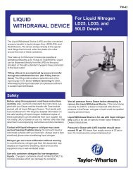
H<strong>and</strong>ling the ContainerThe <strong>XL</strong> Series containers are very rugged liquid cylinders. All cryogenic liquid cylindershave an inner container <strong>and</strong> an outer container with an insulated vacuum space betweenthem. Any abuse (dents, dropping, tip-over, etc.) can affect the integrity of the containersinsulation system.When fully loaded, the <strong>XL</strong>-<strong>55</strong> in argon service will contain <strong>55</strong>1 lb. (2<strong>50</strong> kg) of product.While moving a full container, you may be h<strong>and</strong>ling 821 lb. (372 kg) <strong>and</strong> you should treatthe load accordingly. The attachment points provided on the <strong>XL</strong>-<strong>45</strong>/<strong>50</strong>/<strong>55</strong> will allow you touse a h<strong>and</strong> truck or a hoist to h<strong>and</strong>le these loads properly. Do not attempt to move thesecylinders by any other means. While moving the cylinder, the following precautions shouldbe observed.q Never lay the cylinder on its side. Always ship, operate <strong>and</strong> store the unit in a verticalor upright position.q When loading or unloading the container from a truck, use a h<strong>and</strong> truck, lift gate, craneor parallel loading dock. Never attempt to manually lift the unit.<strong>XL</strong>-<strong>45</strong>, <strong>XL</strong>-<strong>50</strong>, <strong>XL</strong>-<strong>55</strong>Containersq To move the container over rough surfaces, or to lift the container, attach an appropriatedsling to the lifting points cut into the welded support posts, <strong>and</strong> use a portablelifting device that will h<strong>and</strong>le the weight of the container <strong>and</strong> its contents.FREIGHT DAMAGEPRECAUTIONSANY FREIGHT DAMAGE CLAIMS AREYOUR RESPONSIBILITY. Cryogenicliquid containers are delivered to yourcarrier from <strong>Taylor</strong>-<strong>Wharton</strong>’s dock in newcondition. When you receive our productyou may expect it to be in that samecondition. For your own protection, taketime to visually inspect each shipment inthe presence of the carrier’s agent beforeyou accept delivery. If any damage isobserved, make an appropriate notationon the freight bill. Then ask the driver tosign the notation before you receive theequipment. You should decline to acceptcontainers that show damage which mayaffect serviceability.
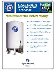
OPERATIONThe <strong>XL</strong>-<strong>45</strong> will store up to 169 liters of product, the <strong>XL</strong>-<strong>50</strong> up to 181 liters <strong>and</strong> 200 litersfor the <strong>XL</strong>-<strong>55</strong>. All three cylinders can deliver either liquid or gas. The following component<strong>and</strong> circuit descriptions are pertinent to the operation of all the containers <strong>and</strong>should be read before attempting operation. The components may be identified on theComponent Location Illustration.<strong>XL</strong>-<strong>45</strong>/<strong>50</strong>/<strong>55</strong>ComponentLocationsInternal Vaporizer – A liquid container for gas service must have an internal heat exchangerthat functions as a gas vaporizer coil to convert liquid product to gas continuouslyduring withdrawal. The <strong>XL</strong>-<strong>45</strong>/<strong>50</strong>/<strong>55</strong> utilizes an internal heat exchanger that is insidethe vacuum space attached to the container’s outer casing. It provides a means of introducingheat from outside the container’s insulated jacket, to vaporize liquid as gaseousproduct is withdrawn. The capacity of this circuit is sufficient to vaporize liquid as gaseousproduct is withdrawn. The capacity of this circuit is sufficient to vaporize product at flowrates up to 3<strong>50</strong> cfh @ NTP (9.2 cu. m/h @ STP). If a greater continuous dem<strong>and</strong> is put onthe vaporizer, an external vaporizer should be added to properly warm the gas <strong>and</strong> avoidmalfunction, or damage, to gas regulators, hoses, <strong>and</strong> other downstream components.Pressure Building – A Pressure Building circuit is used to ensure sufficient driving pressureduring high withdrawal periods. This function is actuated by opening a h<strong>and</strong> valve thatcreates a path from the liquid in the bottom of the container, through the Pressure BuildingRegulator, to the gas space in the top. When the pressure building valve is open, <strong>and</strong> thecontainer pressure is below the pressure building regulator setting, liquid taken from the
inner container is vaporized in a heat exchanger whichis inside the outer casing. The exp<strong>and</strong>ing gas is fed intothe upper section of the container to build pressure. Theresulting pressure will drive either the liquid or gas deliverysystem.Pressure Building is not normally required unless containerpressure drops below the gas output pressure desired.If, for example, the container pressure gauge reads75 psig (5 bar/517 kPa), <strong>and</strong> your gas pressure requirementis 100 psig (6.9 bar/690 kPa), the pressurebuilding valve may be opened to build container pressureto 125 psig (8.6 bar/862 kPa).Economizer – An economizer circuit withdraws gas preferentiallyfrom the head space over the liquid in the container– gas that would otherwise be lost to venting. Excesspressure in the head space of the container isrelieved by allowing gas to flow from this area directly tothe USE valve outlet while gas is being withdrawn fromthe container; yet normal operating pressure is preservedto ensure uninterrupted product delivery. The economizeris automatic <strong>and</strong> requires no operator attention.<strong>XL</strong>-<strong>45</strong>/<strong>XL</strong>-<strong>50</strong>-<strong>XL</strong>-<strong>55</strong>Flow DiagramThe USE Valve - This valve controls the gas outlet thatallows product withdrawal through the internal vaporizer. It has the CGA connection thatmatches the gas service for which the container is configured.The LIQUID Valve – Liquid product is added or withdrawn from the container throughthe connection controlled by this valve. It has the CGA fitting that is required for liquidline connections. The valve is open for fill or liquid withdrawal after connecting a transferhose with compatible fittings to the LIQUID line connection.RELIEF VALVES AND RECOMMENDED REGULATOR SETTINGSNOTE:The economizer <strong>and</strong>pressure buildingfunctions arecontrolled by a singledual action regulator.The pressure deltabetween the pressurebuilding setpoint <strong>and</strong>the economizersetpoint isapproximately 20 psig(1.4 bar/138 kPa). Thisdelta cannot bealtered.Relief Pressure NormalValve Building Economizer OperatingSetting Setting Setting Range22 psig N/A N/A 0-22 psig1.5 bar N/A N/A 0-1.5 bar152 kPa N/A N/A 0-152 kPa230 psig 125 psig 1<strong>45</strong> psig 75-175 psig16 bar 8.6 bar 10 bar 5-12 bar1586 kPa 862 kPa 1000 kPa 517-1207 kPaThe PRESSURE BUILDING Valve – This valve isolates the liquid in the bottom of thecontainer to the Dual Pressure Building/Economizer Regulator. This valve mustbe open to build pressure inside the container.
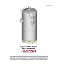
The VENT Valve – This valve controls a line into the head space of the container. It isused during the fill process. The VENT valve acts as a fill point during a pump transfer, orto vent the head space area while liquid is filling the inner container during a pressuretransfer fill through the LIQUID valve.The Pressure Gauge – The pressure gauge displays the internal container pressure inpounds-per-square-inch or in kilo Pascals.PressureBuilding RatesGraphCAUTION:When withdrawinggas from the cylinder,the capacity of theinternal vaporizer canbe exceeded. If gas iswithdrawn at ratesgreater than thevaporizer capacity,liquid or very cold gaswill be discharged.Severe damage toexternal equipmentcould result from theextreme cold.The Full View Contents Gauge – The container contents gauge is a float type liquidlevel sensor that indicates container liquid through a magnetic coupling to a yellow indicatorb<strong>and</strong>. This gauge is an indication of approximate container contents only <strong>and</strong> shouldnot be used for filling; liquid cylinders should be filled by weight.Relief Devices – These cylinders have a gas service relief valve <strong>and</strong> inner containerbursting disc with settings of 230 psig (16 bar/1586 kPa) <strong>and</strong> 380 psig (26 bar/2620 kPa)respectively. A 22 psig (1.5 bar/152 kPa) relief valve is available for liquid delivery applications.WITHDRAWING GAS FROM THE CONTAINERTo withdraw gas from the <strong>XL</strong>-<strong>45</strong>/<strong>50</strong>/<strong>55</strong> connect a suitable pressure regulator to the USEconnection, <strong>and</strong> the output of the regulator to your external equipment. Then open theUSE <strong>and</strong> the PRESSURE BUILDING valves. When the container pressure reaches 125psig (8.6 bar/862 kPa), set the pressure regulator for the desired delivery pressure.
Increasing Gas Supply Capacity – Two or more liquid containers may be manifoldedtogether. Accessory manifolds are available for use in creating a higher capacity gassupply system. The <strong>XL</strong>-<strong>45</strong>/<strong>50</strong>/<strong>55</strong> can supply gas at flow rates 1 up to 3<strong>50</strong> cfh @ NTP (9.2cu.m/h @ STP) using only its internal vaporizer. At low flow rates, the gas supplied will beat near ambient temperature. As the flow dem<strong>and</strong> is increased, the gas will becomeproportionately colder. If greater vaporizing capacity is required, an accessory externalvaporizer is available. When an external vaporizer is used, it must be connected to theUSE valve <strong>and</strong> the regulator moved to the output of the external vaporizer.WITHDRAWING LIQUID FROM THE CONTAINERAttach a transfer hose to the LIQUID connection <strong>and</strong> open the adjacent LIQUID valve.The pressure in the container will drive liquid product out through the valve as long as thecontainer pressure exceeds that of the receiver.VaporizerPerformanceGraphLiquidWithdrawalThe rate of liquid withdrawal from these containersis variable depending on the gas phase <strong>and</strong>the saturation temperature of the liquid.FILLING THE CONTAINERCAUTION:To avoidcontamination, closethe LIQUID valve onan empty containerbefore disconnectingthe transfer line.Cryogenic liquid containers must always be filledby weight to ensure there is enough gas headspace (ullage) for liquid to exp<strong>and</strong> as it warms.Using the procedure below, first determine theproper filled weight of each container. The weightderived is then used in either the Pump Transferof Pressure Transfer filling procedures that follow.
Determine Proper Fill Weight1. Visually inspect the container. Do not attempt to fill containers with broken or missingcomponents.NOTE:The weight calculationincludes the weight ofresidual liquid <strong>and</strong> isapplicable to bothPressure Transfer <strong>and</strong>Pump Transfer fillingmethods.2. Move the container to a filling station scale <strong>and</strong> weight it both with <strong>and</strong> without the fillhose attached to determine the weight of the fill line assembly. The difference is the fillline weight.3. To determine the weight at which the fill should be stopped, add the desired fillingweight (from the table below), the transfer line weight, <strong>and</strong> the Tare Weight from thecontainer’s data plate.FILLING WEIGHTS<strong>XL</strong>-<strong>45</strong> <strong>XL</strong>-<strong>50</strong> <strong>XL</strong>-<strong>55</strong>ARGON 471 lb. (214 kg) <strong>50</strong>5 lb. (229 kg) <strong>55</strong>1 lb. (2<strong>50</strong> kg)WARNING:Filling operationsshould take place onlyin well ventilatedareas. Accumulationsof product gas can bevery dangerous (referto the safetyprecautions in thefront of theseinstructions.) Maintainadequate ventilationat all times.NITROGEN 273 lb. (124 kg) 293 lb. (133 kg) 319 lb. (1<strong>45</strong> kg)OXYGEN 388 lb. (176 kg) 416 lb. (189 kg) <strong>45</strong>4 lb. (206 kg)Pressure Transfer Filling MethodFilling a liquid cylinder using the pressure transfer method is common for 22 psig (1.5 bar/152 kPa) service where the product is used for refrigerant purposes. This method mayalso be used for higher pressure cylinders to increase liquid holding time. A fill is accomplishedby first establishing a pressure difference between the source vessel <strong>and</strong> the <strong>XL</strong>-<strong>45</strong>/<strong>50</strong>/<strong>55</strong> (higher pressure at the bulk vessel). The pressure differential will then push theliquid from the storage vessel to the container being filled. This method is employed whenno transfer pump system is available, or if a greater control over liquid temperature isdesired.Filling the container is accomplished through the LIQUID valve while the VENT valve isopen or partially open to control product pressure. Careful control of pressure will controlthe amount of heat retained in the liquid. Lower pressure results in colder liquid transferredto the container <strong>and</strong> increases, or lengthens, product holding time.Pressure Transfer Filling Procedure (Low Pressure Source) - Once you have determinedthe proper full weight for a container, connect a transfer hose to the LIQUID fittingfrom a low pressure source of liquid.1. Open the supply valve. Then, on the <strong>XL</strong>-<strong>45</strong>/<strong>50</strong>/<strong>55</strong>, open the LIQUID <strong>and</strong> VENT valves tobegin the fill.
2. During the fill, monitor the container pressure <strong>and</strong> maintain a pressure of 10-15 psig(0.7-1 bar/69-103 kPa) by throtting the VENT valve.3. When the full weight is reached, close both the LIQUID <strong>and</strong> VENT valves.4. Close the liquid supply valve <strong>and</strong> open the dump valve on the fill line assembly.5. Disconnect the fill line from the container <strong>and</strong> remove the container from the scale.Pump Transfer Filling MethodWhen a pump is used for filling liquid containers, the fill may be accomplished througheither the VENT valve or the LIQUID valve. Filling through the VENT valve recondensesgas in the area over the liquid in the cylinder <strong>and</strong> reduces product loss during the fill. Thismethod will also result in liquid near the saturation temperature of the supply vessel.Filling through the LIQUID valve may provide colder liquid <strong>and</strong> longer holding time beforethe liquid warms to the point where venting beings, but will require more frequent venting<strong>and</strong> greater product loss.Pressure TransferFilling From a LowPressure SourcePump Transfer Filling Procedure - This method applies only to containers in gasservice that are equipped with a 230 psig (16 bar/ 1586 kPa) relief valve. Liquid is admittedthrough the VENT valve <strong>and</strong> recondenses gas in the head space during the fill. The fill lineis connected from the liquid supply to the VENT valve on the cylinder. Both the fill line <strong>and</strong>the container should be pre-cooled prior to beginning the fill process. Proper full weight isdetermined by the previously explained method.1. Open the supply valve. Then, on the container being filled, open only the VENT valve tobegin the fill. Start the pump at this time.2. Observe the container pressure closely. If the pressure approaches the relief valvesetting (or the dump pressure rating) stop the fill process at the supply <strong>and</strong> open the fillline dump valve to vent excess pressure. As soon as the pressure has dropped to alevel that will allow you to resume the fill, close the dump valve <strong>and</strong> restart the pump (orreopen the supply valve.)3. When full weight is reached, close the VENT valve. Stop pump (where applicable),close liquid supply valve <strong>and</strong> open the dump valve on fill line assembly to vent trappedliquid.4. Disconnect the fill line from the container <strong>and</strong> remove the container from the scale.Fill Hose Kits<strong>Taylor</strong>-<strong>Wharton</strong> fill hose kits for the <strong>XL</strong>-<strong>45</strong>/<strong>50</strong>/<strong>55</strong> are designed to transfer specific liquefiedgases to, or from, the containers. These accessories are comprised of a Fill Tee Assembly<strong>and</strong> a Fill Hose. Cryogenic transfer hoses are constructed of stainless steel for thetransfer of cryogenic liquids <strong>and</strong> are available in four or six feet (1.2 or 1.8 m) lengths witha 3/8 in. NPT fitting on one end <strong>and</strong> CGA service-specific female fitting on the other. A FillTee Assembly consists of a cross fitting with a CGA end fitting, relief valve <strong>and</strong> manualdump valve.Pump Transfer LiquidFill Through VentValveIn use, the CGA Tailpiece couples to the fill connection on the container being filled. TheRelief Valve vents pressure over 3<strong>50</strong> psig (24 bar/2413 kPa) that builds up in the fill linedue to trapped liquid. The Dump Valve is used to allow the operator to blow-down thereceiving container during a pump fill, or to relieve residual pressure from exp<strong>and</strong>ing liquidtrapped in the line before disconnecting the fill line.
Fill Hose KitsFill kits are available with different combinations of hose length <strong>and</strong> fittings for a specificgas service. The following chart identifies the available transfer hoses <strong>and</strong> fill tee assemblies.TRANSFER HOSE CHARTDescription Cylinder End Part(Service/Hose Length) Connections(s) Fittings NumberInert (N2,Ar) Service4 ft. (1.2 m) Stainless Steel LIQUID or VENT Valve CGA 295 to 3/8 in. NPT 1700-9C656 ft. (1.8 m) Stainless Steel LIQUID or VENT Valve CGA 295 to 3/8 in. NPT 1600-9C666 ft. (1.8 m) Stainless Steel USE Valve CGA 580 to 3/8 in. NPT GL<strong>50</strong>-8C51Oxygen Service6 ft. (1.8 m) Stainless Steel LIQUID or VENT Valve CGA 440 to 3/8 in. NPT GL-8C536 ft. (1.8 m) Stainless Steel USE Valve CGA 540 to 3/8 in. NPT GL<strong>50</strong>-8C56VENT TEE CHARTThe vent tee connects to transfer hose to complete a fill line kit. Each assembly includesa 3/8 in. pipe connector to CGA fitting with a 3<strong>50</strong> psig (24 bar/2413 kPa) relief valve, <strong>and</strong>a ball-type dump valve.
Service CGA Connection Part NumberInert (N2, Ar) CGA 295 GL<strong>50</strong>-8C60Read the Safety Precautions in the front of this manual before attempting any repairs onthese containers. Also follow these additional safety guidelines while performing containermaintenance.MAINTENANCEPROCEDURESWARNING:For the O 2SystemUsers: Residue of leakdetectors solutionscan be flammable. Allsurfaces to which theleak detector solutionshave been appliedmust be adequatelyrinsed with potablewater to remove alltraces of residue.Reference CGA G-4.Section 4.9.Never work on a pressurized container. Open the vent valve as a st<strong>and</strong>ard practiceduring maintenance to guard against pressure build-up from residual liquid.Use only repair parts cleaned for oxygen service. Be certain your tools are free of oil<strong>and</strong> grease. This is a good maintenance practice, <strong>and</strong> helps ensure you do not create acombustion hazard when working on containers for oxygen or nitrous oxide service.Leak test connections after every repair. Pressurize the container with an appropriateinert gas or leak testing. Use only approved leak test solutions <strong>and</strong> follow the manufacturer’srecommendations. “Snoop” Liquid Leak Detector is one approved solution, it is availablefrom: Nupro Co. 4800 E. 3<strong>45</strong>th St. Willoughby, Ohio 44094 U.S.A.CONVERTING A CONTAINER TO A DIFFERENT GAS SERVICE<strong>XL</strong>-<strong>45</strong>/<strong>50</strong>/<strong>55</strong> cylinders may be converted from one service to another within the confines ofthe argon, nitrogen, <strong>and</strong> oxygen service for which the containers are designed. Conversionconsists of changing the end connections at the USE, LIQUID, <strong>and</strong> VENT valves;then changing the liquid level gauge scale by changing its plastic cover; <strong>and</strong> revisingproduct decals. Parts are available in kit from for each gas service as illustrated in thefollowing table.Service Change ProcedureBefore removing any parts, empty the container <strong>and</strong> open the vent valve to prevent anypressure build-up in the unit.1. Remove the LIQUID, VENT, <strong>and</strong> USE end fittings, one at a time, with st<strong>and</strong>ard wrenches.Install new fittings from the Gas Service Change Kit, using Teflon tape or anotheroxygen-compatible thread sealant.2. Remove the protective cover over the liquid level gauge. Replace the contents scalewith the scale for the new gas service from the service change kit, then replace theprotective cover.3. Install new fittings for the USE, VENT, <strong>and</strong> LIQUID connections from the Gas ServiceChange Kit. Leak test the fittings you just replaced, <strong>and</strong> change the gas service decalsto complete the conversion.
CAUTION:When changing gasservice, install theproper fittings – DONOT use adapters. Thefollowing proceduresaddress the physicalchanges to thecontainer only. Fordetailed procedureson thedecontamination ofthe container itself,refer to CGA pamphletC-10 “Changes ofService for CylindersIncluding Proceduresfor Inspection <strong>and</strong>ContaminantRemoval.”GAS SERVICE CHANGE KITSKit Valve ConnectionPart No. Gas Service Name DesignationGL<strong>50</strong>-8C35 Oxygen LIQUID CGA 440VENT CGA 440USE CGA 540GL<strong>50</strong>-8C30 Nitrogen LIQUID CGA 295VENT CGA 295VENT CGA 295USE CGA 580GL<strong>50</strong>-8C31 Argon LIQUID CGA 295VENT CGA 295USE CGA 580REGULATOR MAINTENANCEA dual stage, spring-loaded regulator is employed for the pressure building/economizercircuit. This regulator can be adjusted on the container, replaced, or checked <strong>and</strong> adjustedoff the container in a readily fabricated bench adjustment fixture.NOTE:One clockwise turn ofthe adjustment willraise the setpoint byapproximately 30 psig(2 bar/207 kPa). Seethe chart below todetermine the rangeof adjustment for theregulator you areservicing. Do notattempt to set theregulator to a pressureoutside of its designrange.Regulator Adjustment – On Container1. Fill the container with the appropriate liquid product.2. Open the Pressure Building Valve <strong>and</strong> allow the container pressure to stabilize forabout an hour. Note the point where the pressure stabilizes.3. Adjust the screw on the top of the regulator to raise or lower the pressure to thedesired point. When decreasing the setting, the pressure building valve must be closed<strong>and</strong> the container vented to a lower pressure. Then repeat step 2 in order to observethe change.Part No. Normal Setting Range Delta6999-9015 125 psig 75 to 175 psig 20 psig8.6 bar 5 to 12 bar 1.4 bar862 kPa 517 to 1207 kPa 138 kPa
Regulator Removal or Replacement Procedure1. Close manual Pressure Building Valve.2. Vent the container to atmospheric pressure.3. Loosen <strong>and</strong> remove both the tube connections on the pressure building <strong>and</strong> economizeroutput sides of the regulator.4. Remove the regulator from the container by unscrewing the valve body <strong>and</strong> elbow fromthe output of the Pressure Building Valve.5. Repair the regulator <strong>and</strong> readjust its setpoint using the bench test setup.6. To install a replacement or readjusted regulator, apply Teflon tape to the elbow on thecontainer <strong>and</strong> thread the valve body onto the elbow.7. Reconnect the tube connections to the regulator <strong>and</strong> tighten.8. Pressurize the container <strong>and</strong> check it for leaks.NOTE:The regulator hasdirectional gas flow.The arrow on theregulator body mustpoint in directionindicated in the BenchAdjustment Fixtureillustration.Regulator Adjustment – Bench ProcedureAssemble the regulator adjustment fixture, <strong>and</strong> the regulator to be adjusted, as shown inthe accompanying illustration.1. Leak test joints between the high pressure cylinder <strong>and</strong> the dump valve. Joints mustbe leak free before proceeding.2. Close the on/off valve <strong>and</strong> the Dump valve.3. Slightly open the high pressure cylinder valve.4. Set the high pressure regulator above the desired set point for the Pressure Buildingsetpoint.5. Slowly open the on/off valve <strong>and</strong> observe the downstream pressure gauge.RegulatorBenchAdjustmentFixtureNOTE:The economizerportion of theregulator has alreadyopened approximately20 psig (1.4 /138 kPa)below the pressurebuilding setpoint.6. When the regulator under test closes, the P.B. set point may be read on the downstreampressure gauge.7. Close the on/off valve, <strong>and</strong> open the Dump valve.8. To reset the regulator, loosen the lock nut on the adjusting screw. Raise the setpointby turning the adjusting screw clockwise; lower the setpoint by turning the screwcounter-clockwise. After adjustment, repeat steps 5 <strong>and</strong> 6 to check the setting beforereinstalling the regulator on the liquid container.
CHECKING CONTAINER PERFORMANCECryogenic containers are two container, one within the other. The space between thecontainers acts as a highly efficient thermal barrier including high technology insulation, avacuum, <strong>and</strong> a vacuum maintenance system. Each serves a very important part in theuseful life of the container. The high technology insulation is very effective in preventingradiated heat from entering the inner container. Unfortunately, the perfect vacuum cannotbe achieved since trace gas molecules begin to enter the vacuum space from themoment of manufacture. The vacuum maintenance systems consists of materials whichgather trace molecules from the vacuum space. The maintenance system can performits function for years, but it has a limited capacity. When the vacuum maintenancesystem is saturated it <strong>and</strong> no long maintains the vacuum integrity of the container. Thechange will be very gradual <strong>and</strong> my go unnoticed for several years. When the vacuum inthe insulation space is no longer effective, the following symptoms may appear:NOTE:Fill through theLIQUID valve with theVENT valve open. ThePressure Buildingvalve must be closedduring the NER test orP.B. operation willincrease evaporation<strong>and</strong> invalidate testresults.1. With liquid in the container <strong>and</strong> pressure building/vaporizer coil not in use, the outercasing will be much colder than comparative containers.2. Frost, indicating the liquid level, may be visible on the outer casing of the container.3. The container may appear to “sweat” if the air surrounding the container is hot <strong>and</strong>humid.4. The relief valve will open continuously until the container is empty.5. The container will hold pressure for several days but will not hold liquid.NER TestingIf a loss of vacuum integrity is suspected, the container’s Normal Evaporation Rate (NER)should be checked. The test measures the actual product lost over time so you cancompare the results obtained to the NER value in the SPECIFICATIONS table. A testperiod of 48 hours is recommended, after the container is allowed to stabilize, but theformula given produces a Daily NER over any time period.1. Fill the container with 1<strong>50</strong> pounds (68 kg) of liquid nitrogen.2. Close the LIQUID valve <strong>and</strong> the PRESSURE BUILDING valve, leave the VENT valveopen <strong>and</strong> allow it to remain open during the test.3. Allow the container to stabilize for 24 hours, then reweigh it. Record the weight, time<strong>and</strong> date.4. Reweigh 48 hours later. The test is more effective if container is not moved during thisperiod. Record the second date, time <strong>and</strong> weight.The following calculation will provide the actual Normal Evaporation Rate in pounds-perday.Daily normal evaporation is simply half the lost over 48 hours.Daily NER = Weight (Step 3) – Weight (Step 4)Time between Step 3 <strong>and</strong> 4 in hours x 24Compare the results of your test to the “as manufactured” NER value in the SPECIFICA-TIONS section of this manual. A container in service should maintain an NER value of lessthan two time the new specification. Any test result greater than two times the listed valueis indicative of a failed, or failing vacuum. If NER is found to be high, contact <strong>Taylor</strong>-
WARNING:Cold surfaces shouldnever be h<strong>and</strong>led withbare skin. Use gloves<strong>and</strong> other protectiveclothing whenperforming thisprocedure.<strong>Wharton</strong> Customer Service at (334)443-8680 for disposition.FULL VIEW CONTENTS GAUGE MAINTENANCEThe content of these containers is measured with the Full View Contents Gauge. Thedevice consists of the gauge assembly beneath a clear plastic protective cover. When thegauges is assembled, a level indicator ring is magnetically coupled to the top of a floatroad <strong>and</strong> moves up or down with the changing level of liquid in the container. The clearcover over the gauge body <strong>and</strong> level indicator is sealed at assembly to resist fogging of thegauge. This seal should never need to be broken.REMOVING THE FULL VIEW CONTENTS GAUGES1. Vent all pressure from container.2. Remove the protective coating by removing three bolts from the base of the cover.3. Unscrew the gauge body using a wrench on hex fitting at base of the indicator.4. Lift the entire gauge assembly free of the container. The gauge assembly is long <strong>and</strong>may be very cold. Gloves should be used to protect your skin.Calibration Procedure for Liquid Level Contents Gauges1. You will need a column of water approximately 4 ft. (1.2 m) tall. A clear plastic tube 2.0in. (51 mm) dia. with a cap glued to one end is perfect. Place an oxygen servicecontents scale sleeve (P/N GL<strong>50</strong>-9C43) over the sight tube.2. Support the gauge assembly by holding the base of the indicator tube. Care must betaken to prevent interference with the spring action or from misaligning the scale sleeve.Immerse teh aluminum float rod below the water level as illustrated. The gauge assemblymust be held vertically <strong>and</strong> the rod must not touch the side or bottom of the tube.The yellow level indicator of the gauge should indicate a full level reading with theoxygen scale.If the gauge fails to indicate a full liquid level, the assemlby is to be removed from thewater, calibrated <strong>and</strong> retested.To change calibration, loosen locking nut away from the brass calibration nut, the exposedportion of rod becomes longer <strong>and</strong> the gauge yellow b<strong>and</strong> will be lowered.To raise the yellow b<strong>and</strong>, turn rod counterclockwise. The exposed portion becomes shorter.Once you have adjusted calibration, recheck for proper setting. (See illustration.) Afterproper setting has been obtained, lock down nut against calibration nut.3. Once the gauge assembly has been calibrated <strong>and</strong> to read full in water, it must beverified that it reads empy when the aluminum floating rod is suspended in air. Theyellow indicator must be as cloase to the bottom as possible (inner rod will be firmlybottomed out.)If calibration is required to make the gauge read empty in air, it must be rechecked inwater.4. After calibration, you will need to follow contents gauge installation to reinsert gauge.Be sure to dry the assembly before reinserting into the cylinder to prevent ice build-upthat could restrict movement or catch on teh guide ring inside the cylinder.Full View ContentsGauge
NOTE:The yellow b<strong>and</strong> willmove approximately¼ in. (6.4 mm) to each10 turns of the rod.NOTE:Make sure that theGauge Assembly is notbent or out of linebefore reinserting thatgauge into thecontainer.Calibration For<strong>XL</strong>-<strong>45</strong>, <strong>XL</strong>-<strong>50</strong>, <strong>XL</strong>-<strong>55</strong>Contents Gauge InstallationBefore installing a new or repaired gauge, inspect the gasket seals. If any damage isapparent, replace the gasket. (See following page for illustration.)1. When inserting the gauge assembly, lower the float rod through the gauge openinguntil about 8 in. (203 mm) of the float rod remains above the container.2. Grasp the clear cover portion of the gauge assembly with two fingers so that theassembly hangs free <strong>and</strong> “plumb.”3. Lower the assembly about 4 in. (102 mm) slowly <strong>and</strong> try to keep the rod in the centerof the threaded entrance hole as you do. If you are careful during this portion of insertion,you will drop the float rod straight though the guide ring inside the cylinder.4. To confirm that the rod is correctly positioned in the cylinder, stop where you can stillgrasp the top of the rod (See illustration.) <strong>and</strong> try to swing the lower end from side toside.5. When the rod is engaged in the guide ring, the rod will be restricted to lower endmovement of about ½ in. (12.7 mm); if you can feel greater movement, withdraw therode to the point where its top is 8 in. (203 mm) above the gauge opening <strong>and</strong> try
CAUTION:When installing thegauge assembly, caremust be taken toensure that the floatrod is inserted throughthe “guide ring”located on the liquidwithdrawal line insidethe container. If thegauge does notengage this ring, thecontents indicationwill be inaccurate, orthe gauge may bedamaged in use.again.6. When you are satisfied that the float rod is correctly installed, lower the assembly therest of the way into the container until the top portion threads can be engaged.7. Screw the gauge in place <strong>and</strong> h<strong>and</strong> torque to about 20 ft lbf (2.8 kgf m). Leak check theconnection of gauge body to the flange.Contents GaugeInsertion
HAND VALVE REPAIRH<strong>and</strong> valve are an integral part of the container, <strong>and</strong> the valve bodies rarely need replacement.However, the h<strong>and</strong>wheel <strong>and</strong> internal parts of the valves are renewable. Theillustration below are exploded views of the valves replaceable parts used on <strong>Taylor</strong>-<strong>Wharton</strong> liquid containers.Valve Repair KitFits: 3/8 in. or 1/2 in. Rego Globe or 3/8 in. Sherwood valves.KIT PARTS - KIT P/N 17<strong>50</strong>-9C35Item No. Description Qty.1 Screw <strong>and</strong> Washer 12 Spring Retainer 13 Retainer Washer 14 Spring 15 Seal Washer 16 Seal 17 H<strong>and</strong>wheel 18 Bonnet Washer 29 Bonnet 110 Stem Gasket 111 Stem 112 Seat Assembly 113 Bushing 114 Body *TQ Torque 80 ft. lbf (11 kgf m) 1*Not available as a repair partH<strong>and</strong> Valve-Exploded ViewValve Disassembly Instructions1. Open valve by turning h<strong>and</strong>wheel counterclockwise as far as it will go to release anytrapped gas in the system.2. Using a screwdriver, remove H<strong>and</strong>wheel Screw <strong>and</strong> Washer by turning counterclockwiseto allow removal of Spring Retainer, Washer, Spring, Seal Washer, Seal, H<strong>and</strong>wheel<strong>and</strong> Bonnet Washers. Discard these parts.3. Using a large adjustable wrench to hold valve body, remove Bonnet by turned counterclockwisewith a 15/16 in. socket wrench that is capable of developing at least 80 ft. lbf(11 kgf m) torque.4. Remove the following parts from the valve body <strong>and</strong> discard – Stem, Stem Gasket,Seat Assembly <strong>and</strong> Bushing.5. Inspect body <strong>and</strong> clean if necessary; be sure interior <strong>and</strong> seal areas are free from dirt,
esidue <strong>and</strong> foreign particles.Valve Replacement Instructions1. Partially thread Seat Assembly (12) (seat disc first) into large end of Bushing (13)leaving a tang of nipple assembly exposed about 1/8 in. beyond top of Bushing.2. Insert Seat Assembly (seat disc first) with attached Bushing, into valve body untilproperly seated.3. Place Stem Gasket (10) carefully over Stem (11) convex side facing downward.4. Insert slotted end of Stem into valve body, making sure that slot fully engages tang ofSeat Assembly.5. Place Bonnet over Steam <strong>and</strong> while holding square end of Stem to keep it from turning,thread Bonnet (9) into valve body. Hold body with one wrench <strong>and</strong> using another wrench(15/16 in. socket), tighten Bonnet to 80 ft lbf (11 kgf m) torque.6. Install Bonnet Washers over Stem on Bonnet.7. Place H<strong>and</strong>wheel over Stem <strong>and</strong> on Bonnet.8. Install Seal (6) over Steam into recess of H<strong>and</strong>wheel.9. Install Seal Washer (5) over Seal at the bottom of H<strong>and</strong>wheel recess shown.10. With the flat side facing downward, place Retainer Washer (3) on top of Seal.11. Align the holes of these parts <strong>and</strong> place Spring (4) over Seal.12. Place Spring Retainer (2) over assembly as shown, keeping center hole aligned withparts installed in steps 6-11.13. Install Screw <strong>and</strong> Washer (1) over retainer. Tighten firmly with a screwdriver, turningclockwise.14. Turn H<strong>and</strong>wheel completely clockwise to close valve. Re-pressurize container <strong>and</strong>leak check valve.
SHOCK MOUNT FOOT RINGItem No. Description Part No. (<strong>XL</strong>-<strong>55</strong> Only) Qty.1 Rubber Shock Ring <strong>XL</strong><strong>50</strong>-4C18 (GL<strong>55</strong>-4C21) 12 Foot Ring <strong>XL</strong><strong>50</strong>-4C19 (GL<strong>55</strong>-4C19) 13 Hex Nut 6310-0135 44 Washer 6430-0125 <strong>45</strong> Carriage Bolt 6620-0401 4Replacement of Shock Mount Foot Ring1. Empty or transfer all contents of tank. Vent to atmospheric pressure.2. Gently lay the container on its side <strong>and</strong> unbolt the four (4) carriage bolts that attach thefoot ring <strong>and</strong> rubber shock ring to the tank.Shock MountFoot Ring -Exploded View3. Slide off the damaged foot ring <strong>and</strong> rubber shock ring.4. Assemble rubber shock ring into new foot ring <strong>and</strong> force over shock mount ring oncontainer. Use a rubber hammer to drive the rubber shock ring into place.5. Using a 1/2 in. drill bit, drill holes through the rubber so that the carriage bolt slides insmoothly.6. The holes in foot ring must be positioned in alignment with holes in shock mount ring.Using the 4 bolts, washers <strong>and</strong> nuts, fasten the new parts to the container.7. After securing the shock mount ring, gently lift the container to the upright position <strong>and</strong>
TROUBLESHOOTINGthen inspect your work.The following chart is provided to give you some guidance in determining the probablecause <strong>and</strong> suggested corrective action for some problems that may occur with cryogenicliquid containers. This chart is specifically tailored to your <strong>XL</strong>-<strong>45</strong>, <strong>XL</strong>-<strong>50</strong>, or <strong>XL</strong>-<strong>55</strong>.TROUBLESHOOTING CHARTSymptom Possible Cause Corrective ActionConsistently low 1. Relief valve open at low 1. Remove <strong>and</strong> replace reliefoperating pressure. pressure. valve.2. Economizer side of 2. Remove <strong>and</strong> replaceP.B./Economizer Regulator regulator.stuck open.3. Cold liquid. 3. Open pressure building valve.With P.B. inoperative, thecontainer will build pressureover time, or an externalpressure source can be usedto pressurize container.No pressure shown 1. Bad container pressure 1. Remove <strong>and</strong> replace badon container gauge. gauge.pressure gauge. 2. Open inner container 2. Remove <strong>and</strong> replace burstingbursting disc.disc. Pressurize container<strong>and</strong> check relief valveoperation.3. Leaks in valves or 3. Leak test <strong>and</strong> repair leaks.plumbing.For valve repairs, seeMaintenance section.4. Cold liquid. 4. Open pressure buildingcircuit.No pressure showing 1. Broken pressure gauge. 1. Replace pressure gauge.but container is full 2. Vent valve open/P.B. 2. Close vent valve, open P.B.by weight. valve closed. valve.3. Faulty relief valve. 3. Replace relief valve.Container full by 1. Liquid too cold. 1. Open P.B. valve or allowweight <strong>and</strong> Liquidto st<strong>and</strong>.Level Gauge but very 2. Possible leak in vent valve. 2. Rebuild valve.low pressure 3. Faulty relief valve. 3. Replace valve.
TROUBLESHOOTING CHARTSymptom Possible Cause Corrective ActionContainer is cold <strong>and</strong> 1. Vacuum loss. Check NER. 1. Consult with <strong>Taylor</strong>-<strong>Wharton</strong>may have ice or frostfor course of action. Do noton outer casing. Willattempt to put additionalnot hold liquid over-liquid in container.night. Relief valve is 2. Defective P.B./Economizer 2. Look for P.B. coil pattern inventing gas. regulator. ice. Close P.B. valve.Replace or reset regulator.Ice formation on 1. Pressure building valve 1. Replace or rebuild valve.bottom of container not closing properly.when P.B. valve is 2. Leak in pressure 2. Leak test pipingclosed. building system connections <strong>and</strong> tightentopworks.fittings if needed.Container vents Pressure Building/ Remove <strong>and</strong> reset or replacethrough relief valve Economizer Regulator set regulator.when in use.above relief valve setting.Economizer side ofregulator clogged orstuck open.Container vents after This may be caused by Symptom should go awayfill but quits after residual heat vaporizing once container reachesawhile. some liquid inside operating temperature <strong>and</strong>container <strong>and</strong> is a normalcondition.the liquid reaches itssaturation point at containeroperating pressure.Container vents gas Heat leak may be too Perform containercontinuously through great. performance evaluation testrelief valve.per Maintenance section todetermine if containervacuum is adequate.Level indicator stuck Float rod stuck on or in Reinstall. See Contents1/2 full. Yellow float rod guide. Gauge Installation.indicator ring will notmove.Level indicator at Indicator disengaged from Recouple indicator usingbottom of gauge. gauge rod. Caused by engagement ring.Container full of dropping the container.product.
REPLACEMENTPARTSThis replacement part list include a recommended inventory quantity which allows you toorder part on a timely basis to keep all your <strong>XL</strong>-<strong>45</strong>/<strong>50</strong>/<strong>55</strong> containers in service. Whenplacing orders, please use the nomenclature <strong>and</strong> part numbers in this section <strong>and</strong> sendwritten orders to:<strong>Taylor</strong>-<strong>Wharton</strong> Fax: 1-334-443-2209<strong>XL</strong>-<strong>45</strong>/<strong>50</strong>/<strong>55</strong>ComponentLocationsACCESSORIES4075 Hamilton Blvd. Call: 1-334-443-8680Theodore, AL 36590-0568 1-800-898-2657 in USA <strong>and</strong> CanadaAccessories available for use with <strong>Taylor</strong>-<strong>Wharton</strong> <strong>XL</strong> Series containers are:- Manifolds, Automatic <strong>and</strong> Manual - Container H<strong>and</strong> Trucks- Vaporizers adding up to 2<strong>50</strong> cfh - Gas Service Changeover Kits(6.6 cu.m/h) each- Transfer Hoses (O2, N2, <strong>and</strong> AR) - Cryogenic Phase Separators- Fill Tee AssembliesFor additional information concerning the accessory of your choice, please consult theseparate manuals on accessories or call <strong>Taylor</strong>-<strong>Wharton</strong>.
IndexRecommendedNo. Description Part No. For 10 Units1. Dual Regulator, Pressure Building/Economizer 69999-9015 2 Each125 psig (8.6 bar/862 kPa)* 2. Gasket, Glass Filled Teflon, Contents Gauge 7701-0083 5 Each3. Contents Gauge Assembly (Includes Gauge <strong>and</strong> Spring) GL<strong>45</strong>-9C65 1 Each* Float Rod (<strong>45</strong>/<strong>50</strong>) GL<strong>45</strong>-9C96 1 Each(<strong>55</strong>) GL<strong>45</strong>-9C97 1 Each4. Contents Gauge Cover, Protective Clear GL<strong>50</strong>-9C54 4 EachSnap-on indicator, Nitrogen GL<strong>45</strong>-9C75 4 EachSnap-on indicator, Oxygen GL<strong>45</strong>-9C77 4 EachSnap-on indicator, Argon GL<strong>45</strong>-9C76 4 Each5. Screw, Brass, 1/4 in. - 20 UNC x 5/8 in. 6114-1088 10 Each5a. Washer, Lock, 1/4 in., Stainless Steel 6460-2025 10 Each6. Gauge, Pressure 0-400 psig (0-28 bar/0-2758 kPa) 7702-6196 2 Each7. Safety Head 380 psig (26 bar/2620 kPa) 1190-9C21 2 Each8. Relief Valve**22 psig (1.5 bar/152 kPa) 6913-9069 5 Each230 psig (16 bar/1586 kPa) 6913-9070 5 Each9. Valve Repair Kit 17<strong>50</strong>-9C35 3 Each10. Elbow, Male, Brass <strong>45</strong>° 3/8 in. ODT-comp x 1/4 in. 6814-9233 2 Each11. Connector, Lake, Brass, 3/8 in. ODT-comp x 1/4 in. NPT-EXT <strong>45</strong>70-1960 2 Each12. Tube, P.B./Economizer Line GL<strong>45</strong>-9C20 2 Each14. Elbow, Male, 3/8 in. NPT x 1/4 in. NPT <strong>45</strong>° 6814-9241 2 EachEnd Fittings for H<strong>and</strong> Valves15. -USE (CGA 540)-oxygen 7114-0163 5 Each-USE (CGA 580)-argon/nitrogen 7114-0164 5 Each-USE (CGA 320)-carbon dioxide 7114-0181 5 Each-USE (CGA 326)-nitrous oxide 7114-0195 5 Each16. -LIQUID (CGA 440)-oxygen 6514-8992 5 Each-LIQUID (CGA 295)-argon/nitrogen 73<strong>55</strong>-4712 5 Each-LIQUID (CGA 320)-carbon dioxide 7114-0181 10 Each-LIQUID (CGA 326)-nitrous oxide 7114-0195 10 Each17. -VENT (CGA 440)-oxygen 6514-8992 5 Each-VENT (CGA 295)-argon/nitrogen 73<strong>55</strong>-4712 5 Each-VENT (CGA 295)-carbon dioxide 73<strong>55</strong>-4712 5 Each-VENT (CGA 295)-nitrous oxide 73<strong>55</strong>-4712 5 Each* Decal, Warning 1700-9C07 4 Each* Decal, Nitrogen GL<strong>55</strong>-9C51 A/R* Decal, Oxygen GL<strong>55</strong>-9C52 A/R* Decal, Argon GL<strong>55</strong>-9C53 A/R* Decal, UN Number, Nitrogen GL<strong>55</strong>-9C63 A/R* Decal, UN Number, Oxygen GL<strong>55</strong>-9C64 A/R* Decal, UN Number, Argon GL<strong>55</strong>-9C65 A/R* Not illustrated.** Optional/Not Illustrated.