10K and 24K - Taylor-Wharton
10K and 24K - Taylor-Wharton
10K and 24K - Taylor-Wharton

Create successful ePaper yourself
Turn your PDF publications into a flip-book with our unique Google optimized e-Paper software.
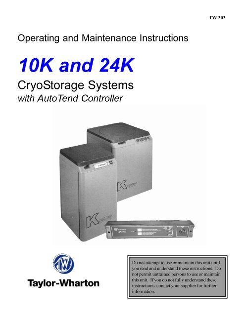
TW-303Operating <strong>and</strong> Maintenance Instructions<strong>10K</strong> <strong>and</strong> <strong>24K</strong>CryoStorage Systemswith AutoTend ControllerDo not attempt to use or maintain this unit untilyou read <strong>and</strong> underst<strong>and</strong> these instructions. Donot permit untrained persons to use or maintainthis unit. If you do not fully underst<strong>and</strong> theseinstructions, contact your supplier for furtherinformation.
SAFETYLiquified GasesExtremely cold refrigerant – cover eyes <strong>and</strong> exposedskin. Accidental contact of the skin or eyeswith any cryogenic liquid or cold gas may cause afreezing injury similar to frostbite. Protect your eyes<strong>and</strong> cover your skin when h<strong>and</strong>ling stored product, orwhen transferring liquid or in any instance where thepossibility of contact with liquid, cold pipes <strong>and</strong> coldgas may exist. Safety goggles or face shield shouldbe worn when transferring liquid. Long-sleevedclothing <strong>and</strong> gloves that can be easily removed arerecommended for skin protection. Cryogenic liquidsare extremely cold <strong>and</strong> will be at a temperature of -320° F (-196° C) under normal atmospheric pressure.Keep equipment well ventilated. Although theliquefied gas refrigerant used in this equipment isnon-toxic <strong>and</strong> non-flammable, it can cause asphyxiationin a confined area without adequate ventilation.An atmosphere that does not contain oxygen forbreathing will cause dizziness, unconsciousness, oreven death. These gases cannot be detected by thehuman senses <strong>and</strong> will be inhaled normally as if theywere air. Ensure that there is adequate ventilationwhere this equipment is used <strong>and</strong> store liquid refrigerantsupply only in a well ventilated area.Liquid Nitrogen System - The liquid nitrogen supplypressure at the inlet to the refrigerator should be inthe range of 10 psig (0.7 bar/69 kPa) to 20 psig (1.4bar/138 kPa) for optimum performance. Higher operatingpressures will increase transfer loses <strong>and</strong> createexcessive turbulence of the liquid in the refrigeratorwhich can generate false signals to the liquid levelcontroller causing the refrigerator to underfill. In “liquidphase” storage applications, excessive turbulencecan cause splashing which could result in personalinjury <strong>and</strong>/or damage to the refrigerator. When installingpiping or fill hose assemblies, make certain asuitable safety relief valve is installed in each sectionof plumbing between shutoff valves. Trapped liquifiedgas will exp<strong>and</strong> as it warms <strong>and</strong> may burst hoses orpiping causing damage or personal injury. A reliefvalve is installed in the refrigerator plumbing to protectthe line between the customer supplied shut-off valve<strong>and</strong> the refrigerator solenoid valve.WARNING: Inlet pressuremust not exceed 22 psig (1.5bar/152 kPa.) Higher pressurescould result in damage toequipment <strong>and</strong>/or sufficientdepletion of oxygen in theatmosphere to cause dizziness,unconsciousness, or death.NOTE: For detailed information on the h<strong>and</strong>ling ofcryogenic liquids refer to the Compressed GasAssociation publication. P-12 “Safe H<strong>and</strong>ling ofCryogenic Liquids” available from Compressed GasAssociation, Inc., 1235 Jefferson Davis Highway,Arlington, VA 22202.ElectricalElectrical shock can kill. The liquid level controllersused with these refrigerators operate from24VAC. However, the external transformer doeshave a 110/120VAC primary. Do not attempt anyservice on these units without disconnecting theelectrical power cord.NOTE: Units are supplied with <strong>Taylor</strong>-<strong>Wharton</strong>approved controllers. If other liquid level controllersare used, please contact <strong>Taylor</strong>-<strong>Wharton</strong> beforeputting the refrigerator into service.Freight Damage PrecautionsAny freight damage claims are your responsibility.Cryostorage systems are delivered to your carrierfrom <strong>Taylor</strong>-<strong>Wharton</strong>’s dock in new condition. Whenyou receive our product, you may expect it to be inthat same condition. For your own protection, taketime to visually inspect each shipment in the presenceof the carrier’s agent before you accept delivery.If any damage is observed, make an appropriatenotation on the freight bill. Then, ask the drive tosign the notation before you receive the equipment.You should decline to accept containers that showdamage which may affect serviceability.
General Information<strong>Taylor</strong>-<strong>Wharton</strong> CryoStorage Systems are designedfor applications where extremely low temperature ofbiological products are required. They are alsoappropriate for industrial or other functions whereliquid nitrogen temperatures <strong>and</strong> high capacity areneeded.The <strong>10K</strong> <strong>and</strong> <strong>24K</strong> refrigerators covered by thispublication are designed for, but not limited to, thelaboratory environment. The <strong>10K</strong> <strong>and</strong> <strong>24K</strong> featuresquare, modular cabinets that facilitate groupingseveral units together in a cryostorage. Both of themodels will accommodate inventory control systemsor provide unobstructed storage area for largerproduct. Models feature full access lid openings,<strong>and</strong> are supplied with casters where limited mobilityfor cleaning purposes is important.These st<strong>and</strong>ard models are equipped with theAutoTend electronic liquid level controller that willmonitor <strong>and</strong> control the supply of liquid nitrogen tothe unit. The instructions for easy operation areprinted on the front panel. The addition of a liquidnitrogen supply <strong>and</strong> inventory control racks forsystematic retrieval of stored product completes thetotal cryostorage systemMaximum Refrigerator ContentsYour cryostorage system has a maximum weightcapacity which is stated in the specifications. Thiscapacity exceeds the maximum amount of liquidnitrogen the refrigerator is capable of holding.Generally, as product is added to liquid storagephase, the stored product <strong>and</strong> inventory controlsystem are heavier than the liquid nitrogen theydisplace. In vapor-phase storage applications,where the liquid refrigerant is found only in thebottom portion of the refrigerator, the weight ofcontents is determined more by weight of the storedproduct.Liquid nitrogen at atmospheric pressure weighs 1.78lb./liter (0.8 kg/liter). To ensure you are not exceedingthe capacity of the cryostorage system, calculatethe weight of the quantity of liquid nitrogen in yourunit <strong>and</strong> subtract the result from the Total AllowableCapacity Weight found in specifications section ofthis publication. All K Series CryoStorage Systemsare designed to support the full weight of liquidnitrogen <strong>and</strong> a complete stainless steel or aluminuminventory control system with boxes <strong>and</strong> specimens...'LPHQVLRQV+HLJKW PP LQ :LGWK PP LQ 'HSWK PP LQ 8VDEOHÃ+HLJKWÃ,QWHUQDO PP LQ ,QWHUQDWOÃ'LDPHWHU PP LQ &DSDFLW\6SDFHÃ9ROXPH FXP FXÃIW /1Ã&DSDFLW\/ (YDSRUDWLRQÃ5DWHÃ/GD\ :RUNÃ(PSW\ NJ OE 7RWDOÃ$OORZDEOHÃ&DSDFLW\:HLJKWÃÃ,QFOXGLQJÃOLTXLGÃUHIULJHUDQWÃDQGÃVWRUHGÃSURGXFW NJ OE 0D[LPXPÃ*URVV:HLJKWÃ NJ OE ,QYHQWUR\Ã&RQWUROÃ6\VWHP6SHFLILFDWLRQV1RÃ[Ã5DFNV 1RÃ6KHOYHV5DFN 1RÃ[Ã5DFNV 1RÃ6KHOYHV5DFN 9LDOÃ&DSDFLW\ÃÃPO %ORRGÃ%DJ Specifications are subject to change without notice1. Maximum required clearance (with the lid open) for the <strong>10K</strong> is 69 in.(1753 m); <strong>24K</strong> is 76 in.(1930 mm).2. Depth with lid open for <strong>10K</strong> is 34 in. (864 mm); <strong>24K</strong> is 48.5 in.(1232 mm).3. Temperature Gradient Suppression System reduces internal diameterby approx. 2/4 in. (6.4 mm). Does not apply to <strong>10K</strong>4. Evaporation rate is nominal. Actual rate may be affected by thenature of the contents, atmospheric conditions, container history, <strong>and</strong>manufacturing tolerances.5. Does not include the weight of the refrigerator itself. Refer toMaximum Refrigerator Contents section.6. Includes the empty weight <strong>and</strong> total allowable capacity weight.7. 5 in. x 5 in. (127 mm x 127 mm) 100 cell box8. 3.0 in x 3.0 in. (76 mm x 76 mm) 25 cell box9. 3 ml vial size: 12.5 mm O.D. internal thread.Fenwal 4R-5461 bag.
KSeries OperationLiquid Nitrogen Supply ConnectionThe package included with the refrigerator includesa filter <strong>and</strong> an elbow. The liquid fill hose from a lowpressure source of liquid nitrogen must be connectedto the inlet through these two fittings. Thisliquid nitrogen source must have a shut-off valve,<strong>and</strong> may be any portable liquid cylinder or a bulksupply. The liquid nitrogen supply pressure at theinlet to the refrigerator should be in the range of 10psig (0.7 bar/69 kPa) to 20 psig (1.4 bar/138 kPa)for optimum performance. Higher operating pressureswill increase transfer losses <strong>and</strong> createexcessive turbulence of the liquid in the refrigeratorwhich can generate false signals to the liquid levelcontroller causing refrigerator to underfill. In “liquidphase”, storage applications, excessive turbulencecan cause splashing which could result in personalinjury <strong>and</strong>/or damage to the refrigerator.If the liquid nitrogen supply pressure at the inlet tothe refrigerator rises above the opening pressure ofthe relief valve on the refrigerator, liquid nitrogen willbe discharged into surrounding area which cancause rapid <strong>and</strong> very dangerous depletion of oxygenin the atmosphere. Once this pressure reliefdevice has opened <strong>and</strong> cooled to liquid nitrogentemperature, it will not reset until it has warmed tonear ambient temperature. THIS COULD PERMITTHE ENTIRE CONTENTS OF THE LIQUID NITRO-GEN SUPPLY SYSTEM TO BE DISCHARGEDINTO THE IMMEDIATE AREA OF THEREFRIGERATOR(S).WARNING: In order to preventthe relief device on nitrogenrefrigerator(s) from openingwhen the system is in operation,the liquid nitrogen supplysystem must be protected by apressure relief device that willopen when the pressure at theinlet to the refrigerator(s) isapproximately 22 psig (1.5 bar/152 kPa). Never install thesupply system pressure reliefdevice into a liquid service line.W A R N I N GINLET PRESSURE MUST NOT EXCEED 22 PSIG(1.5 BAR).HIGHER PRESSURES COULD RESULT IN DAM-AGE TO EQUIPMENT AND/OR SUFFICIENTDEPLETION OF OXYGEN IN THEATOMOSPHERE TO CAUSE DIZZINESS, UNCON-SCIOUSNESS OR EVEN DEATHDO NOT REMOVE THIS LABELDECAL PART NO. R22K-9C43Filling the Refrigerator (Initial Fill)The <strong>10K</strong> <strong>and</strong> <strong>24K</strong> units are using the AutoTendcontroller come preset from the factory to operate.The liquid nitrogen supply pressure at the inlet to therefrigerator should be in the range of 10 psig (0.7bar/69 kPa) to 20 psig (1.4 bar/138 kPa) for optimumperformance. Higher operating pressures willincrease transfer losses <strong>and</strong> create excessiveturbulence of the liquid in the refrigerator which cangenerate false signals to the liquid level controllercausing refrigerator to underfill. In “liquid phase”storage applications, excessive turbulence cancause splashing which could result in personal injury<strong>and</strong>/or damage to the refrigerator.WARNING: Maintain adequate ventilation toprevent asphyxiation hazard. (See Safety Precautions)Power Supply ConnectionConnect the 24 Volt AC power supply to the rear ofthe cryostorage system; then plug the power supplyinto a 110/120 VAC outlet. (See Figure 5 for theElectrical Supply Connections.) Turn on theAutoTend by turning the key on the front panel (seeFigure 5) to the “on” position. The audible alarm maysound during set-up; silence the alarm by pressingthe button labeled MUTE.WARNING: If the fill fails tostop for any reason, quicklyclose the liquid supply valve toprevent overfilling unti thecause of the problem can bedetermined.The unit is now under automatic fill control. Liquidwill be added by the controller as long as the liquidsupply <strong>and</strong> electrical power are maintained.Operating ParametersWhen materials are immersed in liquid nitrogen,they will assume the temperature of the liquid -320°F (-196° C). When material is stored in the vaporphase of the liquid, the liquid nitrogen is still a verycold refrigerant, but the refrigerator’s interior temperatureincreases somewhat as product is storedhigher above the liquid. This temperature differentialis not significant in many biological storage applications,<strong>and</strong> is affected by the amount of productstored in the refrigerator, the type <strong>and</strong> size of inventorycontrol system, <strong>and</strong> the liquid level in the unit.The liquid level in the refrigerator is determined byFigure 1. Warning Label (R23K-9C42)
the position of the sensor probes in the tube locatedat the front of the refrigerator. These probes are setat installation to maintain a specific liquid level. (SeeFigure 4) The cycle repeats when the liquid leveldrops to the low level sensor over time. Sensorprobes may be moved to define new high <strong>and</strong> lowlevels, <strong>and</strong> these levels may be set independently tovary the liquid level differential between fills. Foradjusting the temperature probes see “ChangingLiquid Level” section in this manual.The longest sensor probe contains the Low Level<strong>and</strong> Low Alarm sensors in one pod. The probe withtwo pods contain the High Level <strong>and</strong> the High Alarmsensors. The factory sensor positions will maintain aliquid level between 3.0 in. (7.6 cm) to 6.0 in. (15cm.) The dimensions used for the factory sensorinstallation are shown in Figure 2.Vapor Phase StorageVapor phase storage is normally utilized whenstored product is unable to withst<strong>and</strong> liquid nitrogentemperatures, or when the storage medium (vials,ampules, etc.) is not designed for liquid phasestorage.In a typical vapor phase storage system, the liquidlevel sensors are positioned to maintain the liquidlevel at or below the platform supplied to the inventorycontrol system. This positioning allows storedproduct to be kept at cryogenic temperatures withoutbeing exposed to liquid nitrogen, reducing thepossibility of leakage or cross-contamination. Caremust be taken in the positioning of the level ofrefrigerant in the event of power outages, which maydisable the controller for an extended period of time.Consideration must also be given to liquid nitrogenavailability <strong>and</strong> delivery schedules.Liquid Phase StorageLiquid phase storage is normally utilized when liquidnitrogen temperatures are required to maintainstored product viability <strong>and</strong> the storage mediums areadequate for storage in liquid nitrogen.Factory SettingA=Low SensorB=High SensorYellow & Orange WiresBlack & Brown WiresIn a typical liquid phase storage system, the liquidlevel sensors are positioned to maintain the liquidlevel at or below the top level of the inventory controlsystem. During operation, the upper levels of theinventory control system will at times become exposedas the liquid level fluctuates.Care must be taken to ensure that the liquid levelremains below the bottom of the refrigerator lid.Exposure to liquid nitrogen may result in physicaldamage to the lid. Additionally, operating the refrigeratorwith high liquid levels characteristic of liquidphase storage may result in turbulence during fillcycles. Caution must be exercised if the refrigeratorlid is opened during a fill, <strong>and</strong> appropriated safetyequipment should always be worn.Thermistor Positioning for the AutoTend ControllerB6.0 in (15 cm)A3.0 in. (7.6 cm)ICS PlatformFigure 2. Sensor Positioning for the AutoTend Controller
Using Inventory Control Systems (ICS)The purpose of the inventory control system is tobring order to the storage of many small samples<strong>and</strong> to allow direct retrieval of the particular samplesyou need at any time. It is important to be aware thatwhen you lift an ICS rack from the refrigerator it is ina warmer environment. Learn to locate your samplequickly to avoid unnecessary warming of your storedproduct.Keep ICS inserts (drawers of boxes) <strong>and</strong> dividers ingood repair. Replacement inserts <strong>and</strong> dividers areavailable from your <strong>Taylor</strong>-<strong>Wharton</strong> distributor tokeep your system as efficient as possible.Always wear gloves when h<strong>and</strong>ling ICS racks orstored product, as they are very cold – read theprecautions in the Safety section of these instructions,<strong>and</strong> in <strong>Taylor</strong>-<strong>Wharton</strong> publication TW-10,“H<strong>and</strong>le with Care”, for more detail on h<strong>and</strong>lingproduct stored in liquid nitrogen.If an alternate platform is supplied with your inventorycontrol system, the liquid phase platform in thebottom of your refrigerator may need to be removedto accommodate your inventory control systemplatform.Temperature Gradient Suppression SystemEvery <strong>Taylor</strong>-<strong>Wharton</strong> CryoStorage unit includes aTemperature Gradient Suppression System. TheTemperature Gradient Suppression System is athermal conductor designed to conduct heat downwardtoward the nitrogen reservoir, <strong>and</strong> by doing so,will significantly reduce the temperature gradientbetween the top of the inventory control system <strong>and</strong>the nitrogen reservoir.While specific temperature profiles will vary with theuse of the refrigerator <strong>and</strong> the type of inventorycontrol system used, the Temperature GradientSuppression System is an effective way to lower thetemperature underneath the refrigerator lid withoutnoticeable increasing liquid nitrogen consumption.NOTE: Temperature Gradient Suppression Systemsare specifically designed for use in vaporphase applications <strong>and</strong> will be of little value whenliquid phase storage is used.The chart below represents typical temperaturegradients within a <strong>Taylor</strong>-<strong>Wharton</strong> CryoStorageSystem utilizing the Temperature Gradient SuppressionSystem.Probe Location - Distance from Bottom, in inches2420161284-200 -175 -150 -125 -100Temperature - Degrees Cwith conductive devicewith st<strong>and</strong>ard ICS onlyFigure 3. Temperature Gradient Suppression System
CONTROLLER OPERATIONIntroductionThe AUTO-TEND Control System is designed toprovide simple, reliable liquid level control in yourLN 2freezer. It operates on 24 Volts AC <strong>and</strong> uses atwo-sensor system to open <strong>and</strong> close a solenoidvalve. The liquid level, the sensor condition, thevalve condition, <strong>and</strong> the LN 2supply condition areindicated by lights on the front panel.System Components:AT-01AT-02AT-03AT-04AT-05Installation:AUTO-TEND Control24 VAC Wall TransformerHarness Assembly24 VAC Solenoid ValveSensor AssemblyThe AUTO-TEND Control System is designed todrop into your <strong>Taylor</strong>-<strong>Wharton</strong> Cryogenic refrigerator.The components plug into the back of thecontrol panel as follows: the Harness Assembly hasa 5-pin connector with a red dot. The Solenoid Valvehas a 2-pin connector with a green dot. The sensorassembly has a 6-pin connector with a brown dot.These plug into the mates with the matching dots onthe back of the control panel.your protocol calls for you to “top off” thecryostorage system at the end of a work day or workweek, press the Start button. The unit will full to theupper allowable liquid level <strong>and</strong> stop automatically.You may choose to manually stop the fill by pressingthe STOP button at anytime during the fill.Normal Fill CycleWhen the refrigerator is filled <strong>and</strong> the controller isoperating, the low level <strong>and</strong> low alarm sensors areimmersed in liquid nitrogen (see Figure 4.) Theirresistance values are interpreted by the controller as“in liquid.” A the same time, the high level <strong>and</strong> thehigh alarm sensors are above the liquid pool sendingthe controller a “high” signal. In this condition,the control panel will read “Normal.” As liquid nitrogenevaporates, the liquid level in the refrigeratordrops slowly until the low level sensor is above theliquid <strong>and</strong> send a different signal to the controller.After a delay sufficient to ensure the signal is notfalse, the controller interprets this condition as lowliquid <strong>and</strong> opens the fill solenoid valve admittingmore refrigerant. The refrigerator fills slowly, thecontrol panel will read “LOW” when the liquid level isabove the low level sensor. It will continue to displaythe green filling light until the high level sensor isimmersed in liquid. Once the level of the liquidThe sensor assembly should be installed with theyellow <strong>and</strong> orange wires at the High Level <strong>and</strong> theblack <strong>and</strong> brown wires at the Low Level. These arelabeled for easy reference.The Auto-Tend controller should require not additionalattention to maintain liquid level if an adequatesupply of liquid nitrogen is maintained. IfFigure 4. Normal Fill Cycle Chart
eaches the point of the high level sensor, thecontrol panel will indicate “Normal” <strong>and</strong> will indicatethe start of a new fill cycle. Figure 4 illustrates thiscycle in graph form where liquid level is plottedagainst time, <strong>and</strong> display graphics are shown asthey appear at key points in the cycle.Controller FeaturesLevel LN 2ControllersThe controller is designed to maintain the LN 2levelin the refrigerator within a user-defined range. TheLN 2level will be maintained between the low levelsensor <strong>and</strong> the high level sensor. When the liquidlevel reaches the low level sensor, LN 2will be addedto the refrigerator until it reaches the high levelsensor. There are also two additional sensors locatedin the sensor assembly. The high alarm sensoris located 1 in. (2.54 cm) above the high level sensor.The high alarm sensor is used to shut off theLN 2if the liquid level were to go past the high levelsensor. The low level alarm sensor is located 1 in.(2.54 cm) below the low level sensor. The low alarmsensor is used to provide a warning that a LN 2fillhas not occurred as required to maintain the presetliquid.Basic Operation1.) Automatic Fill: The control will open the solenoidvalve automatically when the liquid levelfalls below the Low Level Sensor. It will continuefilling until the High Level Sensor is covered byliquid.Manual Fill: The Start Fill button can be pressedat any time <strong>and</strong> the solenoid valve will open. Ifthe liquid level is between High Level Sensor<strong>and</strong> the Low Level Sensor, the solenoid will stayopen until the Stop Fill button is pressed or untilthe liquid level covers the High Level Sensor. Ifthe liquid level is above the High Level Sensor,the solenoid valve will stay open while the userpresses the Start Fill Button but will close whenthe user releases the button.Please Note: The maximum time thatthe valve will stay open when theliquid level is above the High Levelsensor is one minute. The user canopen the valve again by simplyreleasing <strong>and</strong> then pressing the StartFill button again.Alarm Conditions: An alarm condition occurswhen a sensor problem develops or the supplytank runs low on LN 2. When an alarm conditiondoes occur, the appropriate light on the frontpanel flashes <strong>and</strong> an audible alarm is activated.Testing the front panel lights: To test all thelights on the control except the Filling LED,press the Stop Fill & Mute button <strong>and</strong> hold for 8seconds.Testing the Remote Alarm: To test the remotealarm, press the Stop Fill & Mute button <strong>and</strong>hold for 13 seconds (5 additional seconds aftertesting the lights.)Remote Alarm: The remote alarm relay has aset of “dry contacts” capable of carrying 5amperes current at 30 volts D.C. The relay is“normal” during any alarm condition. The remotealarm is triggered 30 minutes after an errorcondition occurs. The remote alarm will be resetwhen the error condition is corrected. Pins 1 <strong>and</strong>2 are closed in normal operating condition whilepins 2 <strong>and</strong> 3 are closed in a remote alarmcondition.<strong>10K</strong>/<strong>24K</strong>Figure 5. Electrical Supply Connections for <strong>10K</strong>/<strong>24K</strong>
Figure 6. Front Panel CoverFigure 7. Internal View of Back of Controller Panel
DESCRIPTION OF FRONT PANELKey Lock: This turns the control On/Off. Turning theKey to the 3 o’clock position provides power to thecontrol while rotating the key 12 o’clock positionturns the control off.Start Fill: This button opens the solenoid valve <strong>and</strong>allows LN 2to flow into the freezer.Stop Fill & Mute: This button closes the solenoidvalve <strong>and</strong> stops the flow of LN 2into the freezer. Thisbutton also silences the audible alarm.Filling LED: Lights green to indicate that the solenoidvalve is open.LN 2Level LED: Lights red to indicate that the liquidlevel is above the high level sensor. Lights green toindicate that the liquid level is between the low levelsensor <strong>and</strong> the high level sensor. Lights yellow toindicate that the liquid level is below the low levelsensor.Please note: The LED will not light if thehigh level sensor is submerged in LN 2whilethe low level sensor is located in gas. Theonly time that this can occur is if the sensorsare installed backwards.Sensor Fault LED: Lights red to indicate that asensor fault has occurred. A sensor fault can beeither an open circuit or a short circuit in the sensorassembly.Low LN 2Supply LED: Lights red to indicate that theLN 2supply is low. This is triggered when the liquidlevel does not reach the high level sensor within 1hour of opening the valve.Changing Liquid LevelThe liquid level in the refrigerator is determined bythe position of the sensor probes in a tube near thefront of the refrigerator. These probes have been setat installation to maintain a specific liquid level. Thecontroller operates a fill cycle that adds liquid at lowlevel, fills to a predetermined high level, then stopsthe fill. The cycle repeats when liquid drops to thelow level over time.Sensor probe positions may be changed to definenew high <strong>and</strong> low liquid levels, <strong>and</strong> these levels maybe set independently to vary the liquid level differentialbetween fills. If a higher liquid level is desired,withdraw the sensor tube; for a low level, the sensorsmust be moved further into (down) the sensortube.sensor tube may restrict movementof sensor probes in thetube. Do not pull excessively onsensor wiring while attemptingto change sensor position. Itmay be necessary to removethe sensor from the container<strong>and</strong> allow it to thaw before thesensor can be repositioned.Increasing the distance between low <strong>and</strong> highsensor probes allows greater liquid level fluctuation,less frequent filling <strong>and</strong> reduced fill loses; decreasingthe distance has the opposite effect.To set the liquid level to a different point, or tochange the level differential, the sensors must berepositioned. Their position within the sensor tube isheld in place by the sensor tube plug, which is splitto allow the sensor leads to pass through. Thesensor tube plug holds the sensors at the positionnecessary to maintain a specific liquid levels.Two different sensor heights are specified by theirposition within the sensor tube. The low <strong>and</strong> highsensor pods are separately positioned to set theliquid levels at which the controller will start orterminate each fill cycle. Insert the high <strong>and</strong> lowlevel sensor leads into the perforated sensor tube tothe desired height. Mark the sensor leads at the topof the sensor tube. Pull the leads out just enough toinstall the sensor tube plug around the marks on thesensor leads. Insert sensor plug securely into themouth of the tube. Perform this operation carefully,so the sensor leads are not damaged.NOTE:CAUTION:The high level sensors must be atleast 2.0 in. (5.1 cm) above the lowlevel sensor pod.The high level sensor pod must beat least 8 in. (20 cm) below the topof the sensor tube container toprevent the lid from floating onliquid.After repositioning sensors, check to be sure thesensor tube is secure <strong>and</strong> turn the controller on. Thecontroller should fill the refrigerator to the new liquidlevel. After sensors are repositioned, the controllershould maintain the liquid pool at the new operatinglevel.Remote Alarm ConnectionRelay connections are provided on an external foruser installation of a remote alarm circuit (see FigureCAUTION:Ice or frost in the
12(COMMON)3ALARM RELAY(IN ALARM CONDITION)Figure 8. Remote Alarm ConnectionFigure 9. AutoTend Sensor Installation32CONNECTOR(Pin View)Sensor Leads18.) Wiring external power supply <strong>and</strong> alarm devicesmust be supplied by the user. During an alarmcondition, contacts 1 & 2 are open <strong>and</strong> contacts 2 &3 are open.MAITENANCEK Series CryoStorage MaintenanceFilter Cleaning InstructionsThe container might not fill properly if the filter isclogged with ice or dirt. To clean the filter, first closethe supply valve to the refrigerator. Vent the fill lineof all pressure. Remove <strong>and</strong> warm the filter toambient temperature. Purge the filter from bothdirections with dry nitrogen gas or dry oil-free air.Rinse the filter with alcohol <strong>and</strong> purge it again withdry nitrogen gas or dry oil-free air to clear contaminants.If cleaning process doesn’t clear the blockage,replace with a new filter (P/N 7631-1075.)Defrosting your K Series CryoStorage SystemAll liquid nitrogen storage systems are subject to ice<strong>and</strong> frost buildup over time. Regular preventivemaintenance programs should be instituted toremove ice <strong>and</strong> frost from the sensor <strong>and</strong> fill tubes<strong>and</strong> from the refrigerator lid.Sensor Tube PlugSensor TubeIce <strong>and</strong> frost build up in the sensor tube may resultin false readings being relayed to the controller fromthe sensors. Ice can form a thermal barrier around alevel sensor, rendering it insensitive to the temperaturedifferences between vapor <strong>and</strong> liquid. Sensors<strong>and</strong> thermocouple should be removed regularly <strong>and</strong>inspected for ice <strong>and</strong> frost build up.NOTE:Ice or frost in the sensor tube mayrestrict the movement of sensorprobes in the tube. Do not pull excessivelyon the sensor wiring whileattempting to change sensor position.It may be necessary to remove thesensor tube from the container <strong>and</strong>allow it to thaw before the sensorscan be repositioned.Ice <strong>and</strong> frost buildup in the fill tube may block theflow of liquid nitrogen into the refrigerator during fill.This blockage can result in the liquid level droppingto dangerously low levels, <strong>and</strong> may result in the LowAlarm sensor being activated. In addition, a fill lineblockage may cause the low LN 2Supply Alarm to beactivated. If the fill line becomes blocked, it must beremoved from the refrigerator, allowed to thaw toroom temperature, <strong>and</strong> purged with dry nitrogen oroil-free dry air to remove all traces of moisturebefore being re-installed.
Excessive ice <strong>and</strong> frost buildup may occur on therefrigerator lid if the lid id left open or the liquid is tooclose to the underside of the lid. To defrost the lid,open the lid to the fully open position. Clean the ice<strong>and</strong> frost from the underside of the lid by allowing itto thaw slightly <strong>and</strong> wiping with a clean, lint-feecloth. Care must be taken to insulate the inventorycontrol system from high temperatures, which mayaffect the viability of the stored product.Excessive ice <strong>and</strong> frost buildup on the lid may occurif the lid is miisaligned or the insulative gasketmaterial is damaged. Should this occur, pleasecontact your <strong>Taylor</strong>-<strong>Wharton</strong> distributor for assistance.Cleaning your K Series CryoStorage SystemThe Cryogenic vessel of all K Series CryoStorageSystems may need to be cleaned <strong>and</strong> sterilized ifthe type of stored product is changed or the unit istaken out of service. The vessel must be cleaned<strong>and</strong> sterilized, regardless of the type of storedproduct, prior to return to <strong>Taylor</strong>-<strong>Wharton</strong> for repairof maintenance. 2To clean <strong>and</strong> sterilize your K Series CryoStoragesystem, first turn the unit off. Disconnect the powersource <strong>and</strong> the liquid nitrogen source. Remove allstored product <strong>and</strong> inventory control system components.Allow the residual liquid nitrogen to evaporate<strong>and</strong> the cryogenic vessel to warm to ambient temperature.Spray the entire inner vessel surface with ampleamounts of an approved disinfectant. 3 Allow surfacecontact to be maintained for a minimum of fiveminutes. Rinse the inner vessel with water, removeall water <strong>and</strong> debris, <strong>and</strong> towel dry the surface.Spray the inner vessel surface with a 70% alcohol towater solution <strong>and</strong> maintain surface contact forfifteen minutes. Rinse the inner vessel surface withwater <strong>and</strong> towel dry.WARNING: Never use hollow rods or tubes asdipsticks. When a warm tube is inserted intoliquid nitrogen, liquid will spout from the top ofthe tube <strong>and</strong> may cause personal injury.Normal Evaporation Rate (NER) TestIf the nitrogen consumption of your K SeriesCryoStorage System seems excessive, it may beappropriate to perform an estimated Normal EvaporationRate (NER) test on the unit. To perform anNER Test:1. Fill the CryoStorage unit to the “High Level”sensor.2. Allow a 24-hour cool down.3. Measure the liquid nitrogen level with a plastic orwooden rule.WARNING: Never use hollow rods or tubes asdipsticks. When a warm tube isinserted into liquid nitrogen, liquidwill spout from the top of the tube<strong>and</strong> may cause personal injury.4. Close <strong>and</strong> lock the lid of the CryoStorage Systemfor forty-eight (48) hours.5. Open the CryoStorage System <strong>and</strong> measure theliquid nitrogen level. Typically, liquid nitrogenlevels will drop approximately 1 in. (25.4 mm) perday. If your measurement indicates a drop inexcess of 2.0 in. (51 mm) per day, please contactyour <strong>Taylor</strong>-<strong>Wharton</strong> distibutor or <strong>Taylor</strong>-<strong>Wharton</strong> Customer Service at (334)443-8680 forfurther information.Auto-Tend Controller MaintenanceWARNING:Unplug the transformer from thewall before proceeding with anyrepairs.The Auto-Tend has been designed for easy setup<strong>and</strong> maintenance. All connectors on the controllerare uniquely identified snap-on plugs. The sensor,assembly, solenoid valve, power, remote alarm <strong>and</strong>data lines can be connected or disconnected inseconds. The controller is connected to the backelectrical panel with a 10 wire cable with the appropriatesnap-on connectors.Installing the ControllerRemove the cabinets top, follow the steps in Figure10 to remove the four (4) screws holding the trim(escutcheon) where the controller will be mounted.Remove four (4) screws from the top of the refrigerant<strong>and</strong> life the cabinet top to gain access to thearea between the cabinet <strong>and</strong> the insulated innervessel. The cabinet top may only be raises asshown in Figure 10 because of the lid hinges. Donot remove the hinged lid. After the cabinet top isloosened <strong>and</strong> propped up, this will allow access tothe location where the electrical supply connectionswill be mounted.Install the electrical supply connections panel to theback of the refrigerator. (See Figure 5.) Feed thewiring harness from the electrical supply connectionspanel to the front of the refrigerator <strong>and</strong>through the opening to where the controller will be
mounted. Attach the electrical supply connections tothe controller board. Be sure to follow all of theinstallation procedures for the sensor probes <strong>and</strong>solenoid valve before you reattach the cabinet top.Attach the controller to the cabinet top with the two(2) supplied screws. Place the trim (escutcheon)over the controller <strong>and</strong> screw in the four (4) screws.Be sure that all of the necessary installation procedureshave been completed before you start to fillthe refrigerator. To start filling, refer to Filling theRefrigerator (Initial Fill) section of this manual.Removing the ControllerTo remove the control panel, follow the steps illustratedin Figure 10 to remove the four (4) screwsholding the trim (escutcheon) around the controllermounting opening at the front of the refrigerator.Remove the two (2) screws from the controller <strong>and</strong>lift it from the refrigerator far enough to detach itselectrical wiring. Remove four (4) screws from thetop of the refrigerator <strong>and</strong> lift the cabinet top to gainaccess to the area between the cabinet <strong>and</strong> theinsulated inner vessel. The cabinet top may only beraised as shown in Figure 10 because of the lidhinges. Do not remove the hinged lid. After thecabinet top is loosened <strong>and</strong> propped up, the electricalconnection wiring may be detached to allow theback panel connection. At the completion of maintenance<strong>and</strong> repairs, reattach the electrical connectionwiring to the controller. Install the controller using theprocedure outlined for your refrigerator in Installingthe Controller section.Installing the Sensor ProbesFor procedures for installing the sensor probes referto the section titled Changing Liquid Level in thissection of the manual.Removing the Sensor ProbesRemove the controller using the procedures outlinedin the Removing the Controller section. Disconnectthe sensor probe lead connection from the controllerboard. Carefully remove the sensor tube plug fromthe sensor tube <strong>and</strong> remove the sensor leads fromthe plug.To install the new sensor probes, refer to theprocedudure Changing Liquid Level. Installing theSolenoid ValveTo install a new solenoid valve, attach the connectingplumbing to the inlet <strong>and</strong> outlet connections ofthe valve using Teflon tape. Refer to Figure 11 forplumbing arrangement. Attach the compressionfitting to the fill tube first <strong>and</strong> then connect to theoutlet side of the solenoid valve. Position the solenoidvalve onto the solenoid valve bracket <strong>and</strong>tighten the two (2) mounting screws. Attach thesolenoid valve lead connection to the controllerboard. At the completion of maintenance or repairs,install the controller using the procedure outlined foryour refrigerator model in the Installing the Controllersection.Removing the Solenoid ValveRemove the controller using the procedure outlinedfor your particular refrigerator model in the Removingthe Controller section. Disconnect only thesolenoid valve lead connection from the controllerboard. Remove the back plumbing cover of therefrigerator to gain access to the plumbing <strong>and</strong>solenoid valve. (See Figure 11)NOTE:After disconnecting the solenoid valveleads, do not pull on wires. The wiresare tied <strong>and</strong> spiral wrapped together.To remove the solenoid valve, loosen the compressionfitting that connects the plumbing tubing in thefill tube. Unscrew the two (2) mounting screws thathold the solenoid valve to the solenoid bracket.Then remove the solenoid valve <strong>and</strong> its associatedplumbing. Disconnect the plumbing from the inlet<strong>and</strong> outlet side of the solenoid valve. To install a newsolenoid valve, refer to the procedure Installing theSolenoid Valve section.NOTE:Ice or frost in the sensor tube mayrestrict the movement of the sensorprobes in the tube. Do not pull excessivelyon the sensor wiring whileattempting to remove sensors. It maybe necessary to remove the sensortube from the container <strong>and</strong> allot it tothaw before the sensors can beremoved.2All K Series Cryostorage Systems must be cleaned <strong>and</strong> sterilized prior to return to <strong>Taylor</strong>-<strong>Wharton</strong> for repair or maintenance <strong>and</strong> must be accompanied by a written statement to thiseffect. Any K Series CryoStorage System received without this statement will be returned to thesender, freight collect. Contact Customer Service at (334) 443-8680 for further information.3For cleaning <strong>and</strong> sterilizing of the K Series CryoStorage Systems, <strong>Taylor</strong>-<strong>Wharton</strong> recommendsEXSPOR ä Cold Sterilant, manufactured by Alcide Corp., 8561 154 th Ave., NE, Redmond, WA98052 or equal. Write or call Alcide Corp. at (800)543-2133 for complete information, pricing <strong>and</strong>availability.
Figure 10. Removing the cabinet top of the <strong>10K</strong> <strong>and</strong> <strong>24K</strong>Figure 11. Rear Panel/Plumbing for <strong>10K</strong> <strong>and</strong> <strong>24K</strong>
7528%/(6+227,1*6\PSWRP 3UREDEOHÃ&DXVH &RUUHFWLYHÃ$FWLRQ1RÃUHVSRQVHÃIURPDÃ1RÃ3RZHUDÃ&KHFNÃSOXJVÃDQGÃSRZHUFRQWUROOHUVRXUFHÃ&KHFNÃ32:(5ÃNH\+LJKÃ1LWURJHQÃFRQVXPSWLRQDà +LJKÃ1(5ÃRQÃVXSSO\FRQWDLQHUEà /LTXLGÃ/HYHOÃWRRÃKLJKFà &RQWDLQHUÃKDVÃORVWYDFXXP Gà ([FHVVLYHÃQLWURJHQHYDSRUDWLRQÃEHWZHHQVRXUFHÃDQGÃUHIULJHUDWRU([FHVVLYHÃIURVWÃRUÃIUR]HQÃOLG DÃOLTXLGÃOHYHOÃWRRÃFORVHÃWRXQGHUVLGHÃRIÃOLG/2 : Ã$ /$ 5 0 ÃLQGLFDWLRQ DÃOLTXLGÃOHYHOÃEHORZ ÃORZVHQVRU) LOOÃZ LOOÃQRWÃVWDUWÃQRUHIULJHUDQWÃHQWHULQJÃXQLWDà 5HIULJHUDQWÃVRXUFHHPSW\Eà 2SHQÃZLULQJÃWRÃVROHQRLGYDOYHFà )DXOW\ÃVROHQRLGÃYDOYHGà )LOWHUÃSOXJJHGÃRUVDWXUDWHGÃZLWKÃPRLVWXUHHà 5HIULJHUDQWÃERLOVÃDZD\EHIRUHÃUHDFKLQJÃXQLWÃGXHWRÃH[FHVVLYHÃILOOÃOLQHOHQJWK+,*+Ã$/$50ÃLQGLFDWLRQ DÃOLTXLGÃOHYHOÃDERYHÃWKHKLJKHVWÃVHQVRU) LOOÃ: LOOÃ1 RWÃ6 WRS Dà VROHQRLGÃYDOYHÃIUR]HQRSHQEà )DXOW\ÃVROHQRLGÃYDOYH(OHFWULFDOÃVKRFNÃIURPDÃLQWHUQDOÃVKRUWÃFLUFXLWFRQWDFWÃZLWKÃPHWDOÃKRXVLQJ6(1625Ã)$8/7ÃLQGLFDWLRQDà VHQVRUÃSUREHFRQQHFWLRQVEà GHIHFWLYHÃVHQVRUÃSUREHVZLWFKDà &RQWDFWÃ\RXUÃQLWURJHQVXSSOLHUEà /RZHUÃKLJKÃOHYHOÃVHQVRUFà &KHFNÃHYDSRUDWLRQÃUDWHDJDLQVWÃPLQLPDOÃYDOXHVLQÃ6SHFLILFDWLRQVGà 6KRUWHQÃLQOHWÃSOXPELQJÃLISRVVLEOHñÃLQVXODWHSLSLQJÃWRÃUHIULJHUDWRUDà ORZHUÃKLJKÃOHYHOÃVHQVRUDÃ3 UHVVó6 7$ 5 7Ã),//´Ã,IUHIULJHUDWRUÃVWLOOÃZ RQWÃILOOVHHó) LOOÃZ LOOÃQRWÃ6 WDUW´Dà UHSOHQLVKÃVXSSO\Eà FKHFNÃDOOÃFRQQHFWLRQVFà 5HSODFHÃVROHQRLGÃYDOYHGà &OHDQÃRUÃUHSODFHÃSDUW1RÃÃ)RUFOHDQLQJÃSURFHGXUHVVHHÃVHFWLRQÃWLWOHGÃ)LOWHU&OHDQLQJÃ,QVWUXFWLRQVHà ,QVXODWHÃDQGRUÃVKRUWHQILOOÃOLQHÃSOXP ELQJÃIURP/1 ÃVXSSO\DÃFORVHÃOLTXLGÃVRXUFHÃYDOYHDQGÃVHHó)LOOÃ: LOOÃ1 RWÃ6 WRS´Dà FORVHÃVXSSO\ÃYDOYHÃDQGWKDZÃVROHQRLGÃYDOYHEà 5HSODFHÃVROHQRLGÃYDOYHDÃÃÃGLVFRQWLQXHÃXVH6 HUYLFHÃFRQWUROOHUDà UHPRYHÃFRQWUROOHUÃDQGFKHFNÃWKHUPLVWRUÃSUREHFRQQHFWLRQVEà 5HS ODFHÃSUREH
REPLACEMENT PARTS5HIULJHUDWRU3DUWV.N . .&DELQHW%DFN3DQHO 5.& 5.&&DELQHW)URQW3DQHO 5.& 5.&&DELQHW6LGH3DQHO 5.& 5.&&DELQHW7RS3DQHO 5.& 5.&*DVNHW.LW 5.& 5.&/LG$VVHPEO\ 5.& 5.&/LG%RRW 5.& 5.&/LG 5.& 5.&(VFXWFKHRQ&RQWURO3DQHO7ULP 5.& 5.&%DFN&RYHU3OXPELQJ 5.& 5.&&DVWHU)RXUUHTXLUHG )LOO7XEH$VVHPEO\ 5.& 5.&6HQVRU7XEH 5.& 5.&3QHXPDWLF6SULQJLQPP6WURNH)RUFH +LQJH7RS6HFWLRQ 5.& 5.&+LQJH%RWWRP6HFWLRQ 5.& 5.&'HFDO/LG:DUQLQJ 5.& 5.&'HFDO:DUUDQW\5&5&'HFDO:DUQLQJ 5.& 5.&7HPSHUDWXUH*UDGLHQW6XSSUHVVLRQ6\VWHPV 1$ 5.&7HPSHUDWXUH*UDGLHQW6XSSUHVVRU6WUDSV 1$ 5.&,QYHQWRU\&RQWURO6\VWHP,&63ODWIRUP 5.& 5.&,QYHQWRU\5DFNYLDOV>VKHOYHVWDOOIRULQPPER[HV@ 5.& 5.&,QYHQWRU\5DFNYLDOV>VKHOYHVWDOOIRULQPPER[HV@ 5.& 5.&/HYHO&RQWUROOHU(OHFWULFDO0HFKDQLFDO3DUWV&RQWURO3DQHO$XWR7HQG6HQVRU7XEH3OXJ6HQVRU$VVHPEO\$XWR7HQG5HPRWH$ODUP3OXJ7UDQVIRUPHU$&(OHFWULFDO3DQHO$VVHPEO\$XWR7HQG/LG6ZLWFK3OXPELQJ$VVHPEO\$XWR7HQG6ROHQRLG9DOYH$VVHPEO\9$&5HOLHI9DOYHSVLJEDUN3DóLQ137)LOWHU$VVHPEO\..5.&5.&5.&