download - Evides
download - Evides
download - Evides

Create successful ePaper yourself
Turn your PDF publications into a flip-book with our unique Google optimized e-Paper software.
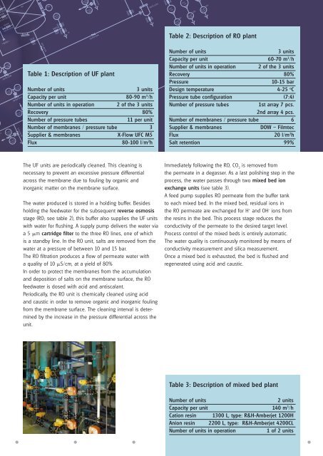
Table 1: Description of UF plantNumber of units3 unitsCapacity per unit 80-90 m 3 /hNumber of units in operation 2 of the 3 unitsRecovery 80%Number of pressure tubes11 per unitNumber of membranes / pressure tube 3Supplier & membranesX-Flow UFC M5Flux80-100 l/m 2 h Table 2: Description of RO plantNumber of units3 unitsCapacity per unit 60-70 m 3 /hNumber of units in operation 2 of the 3 unitsRecovery 80%Pressure10-15 barDesign temperature4-25 o CPressure tube configuration (7:4)Number of pressure tubes1st array 7 pcs.2nd array 4 pcs.Number of membranes / pressure tube 6Supplier & membranesDOW – FilmtecFlux20 l/m 2 hSalt retention 99%The UF units are periodically cleaned. This cleaning isnecessary to prevent an excessive pressure differentialacross the membrane due to fouling by organic andinorganic matter on the membrane surface.The water produced is stored in a holding buffer. Besidesholding the feedwater for the subsequent reverse osmosisstage (RO; see table 2), this buffer also supplies the UF unitswith water for flushing. A supply pump delivers the water viaa 5 µm cartridge filter to the three RO lines, one of whichis a standby line. In the RO unit, salts are removed from thewater at a pressure of between 10 and 15 bar.The RO filtration produces a flow of permeate water witha quality of 10 µS/cm, at a yield of 80%In order to protect the membranes from the accumulationand deposition of salts on the membrane surface, the ROfeedwater is dosed with acid and antiscalant.Periodically, the RO unit is chemically cleaned using acidand caustic in order to remove organic and inorganic foulingfrom the membrane surface. The cleaning interval is determinedby the increase in the pressure differential across theunit.Immediately following the RO, CO 2is removed fromthe permeate in a degasser. As a last polishing step in theprocess, the water passes through two mixed bed ionexchange units (see table 3).A feed pump supplies RO permeate from the buffer tankto each mixed bed. In the mixed bed, residual ions inthe RO permeate are exchanged for H + and OH - ions fromthe resins in the bed. This process stage reduces theconductivity of the permeate to the desired target level.Process control of the mixed beds is entirely automatic.The water quality is continuously monitored by means ofconductivity measurement and silica measurement.Once a mixed bed is exhausted, the bed is flushed andregenerated using acid and caustic.Table 3: Description of mixed bed plantNumber of units2 unitsCapacity per unit 140 m 3 /hCation resin 1300 L, type: R&H-Amberjet 1200HAnion resin 2200 L, type: R&H-Amberjet 4200CLNumber of units in operation1 of 2 units