BiN-Wall Bridge aBUtMeNts teCHNiCal gUide - Armtec
BiN-Wall Bridge aBUtMeNts teCHNiCal gUide - Armtec
BiN-Wall Bridge aBUtMeNts teCHNiCal gUide - Armtec

You also want an ePaper? Increase the reach of your titles
YUMPU automatically turns print PDFs into web optimized ePapers that Google loves.
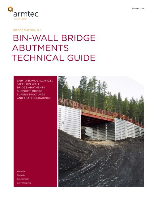
_ARMTEC.COM<strong>Bridge</strong> Materials /BIN-WALL BRIDGEABUTMENTSTECHNICAL GUIDELIGHTWEIGHT, GALVANIZEDSTEEL BIN-WALLBRIDGE ABUTMENTSSUPPORTS BRIDGESUPER-STRUCTURESAND TRAFFIC LOADINGSVersatileDurableEconomicalEasy shipping
_BIN-WALL BRIDGE ABUTMENTShistory and applicationFor economy in the construction of access roads or highways, it is essential thatefficient designs be employed to reduce material costs and time on the project.The most costly ingredient in building roads is often bridge construction, whichalso can extend the job completion considerably.To solve these problems, <strong>Armtec</strong> developed galvanized steel Bin-<strong>Wall</strong> Abutments.This type of abutment has been used on hundreds of bridges built in Canada overthe past 30 years. Working alongside the owner’s technical representative, <strong>Armtec</strong>will develop a custom Bin-<strong>Wall</strong> Abutment solution that conforms to the specifieddesign criteria and site conditions. The Bin-<strong>Wall</strong> Abutment Inquiry Data Sheetlocated in this brochure will assist to identify and collect key site parameters._typical applications• Remote wilderness roads• Logging, mining and otheraccess roads• Provincial and municipalhighways and roadsAdvantages of Bin-<strong>Wall</strong> <strong>Bridge</strong> Abutments• Easily transported because individualcomponents are nested into acompact, lightweight load• Economical material supplyand installation costs• All components can be easily handled,eliminating the need for heavyequipment• Components are easily boltedtogether for fast construction,assembled in place or off-site andlifted into position• No waiting for formwork, curingtime, etc.• All-weather construction• Proven strength and durability• All components are galvanized• No footings are required• Abutments are flexible and willaccommodate minor settlementand movement• Can be salvaged and reused atanother locationElbow Falls and Bragg Creek, AB –bin-wall bridge abutmentbin-wall <strong>Bridge</strong> abutmentBak Creek Nungessor Rd, Red Lake, ON –bin-wall bridge abutment
_BIN-WALL BRIDGE ABUTMENTSBIN-WALL BRIDGE ABUTMENTInquiry Data SheetVARIESREAR FACE3,048 mmTYPBEARINGPADWING WALLDEFLECTIONANGLE(x)WING WALL LENGTH (ix)REQUIRED BRIDGE DATATOTAL BRIDGE WEIGHT (i)BRIDGE DECK WIDTH (ii)NO. OF DRIVING LANES (iii)FRONTFACEBRIDGE DECK WIDTH (ii)ABUTMENT LENGTH (viii)PLAN VIEWLIVE LOADDESIGN VEHICLE (vi)1,000mmMINFILL HEIGHT (v)200mmLIFTSTYPBRIDGE SPAN (iv)(c/c BEARING PAD)BINWALLHEIGHT (vii)150 DIA PERFORATED SUB-DRAINGRADE PLATE BEARING ON 200mmGRANULAR CUSHION (LOOSE)200ELEVATION VIEWALLOWABLE BEARINGPRESSURE (xi)Required Data Required Data Typical Design Vehiclesi Total <strong>Bridge</strong> Weightvii Abutment (Bin-<strong>Wall</strong>) HeightCL-625 (Highway)ii <strong>Bridge</strong> Deck Widthviii Abutment (Bin-<strong>Wall</strong>) LengthCL-800 (Highway)iii No. of Driving LanesWingwall Height (Not Shown)Logging Truck - 75 Toniv <strong>Bridge</strong> Spanix Wingwall LengthLogging Truck - 100 Tonv Fill Heightx Wingwall Deflection AngleLogging Truck - 150 Tonvi Live Load Design Vehiclexi Allowable Bearing PressureOther (Specify)SelectProject Name370 Speedvale Ave. W. Suite 3Guelph ON N1H 7M7Canada<strong>Armtec</strong> is a leading Canadian infrastructure and construction materials companycombining creative engineered solutions, relevant advice, dedicated people, provenproducts and a national presence with a local focus on exceptional customer service.
_BIN-WALL BRIDGE ABUTMENTStypical bin-wall abutmentcross-sectionFigure 2Figure 1StringerstiffenerReinforced concrete ortimber bearing padFigure 21.3m1.0mTop of RoadSpacer stiffenerFill HeightRear cornerverticalconnectorNote 4*Note 11*TheoreticalFailure PlaneGranular BackfillStringersVertical connectorGrade plateSpacersFront cornervertical connector* See Design Notes (opposite)Subdrainmaximum allowable bin heightsHighway LoadingFillDesign Vehicle–L-60 or CL-625Height Design B Design C Design D Design Emm mm mm mm mm600 3,758 4,977 5,791 6,197900 4,167 4,977 5,791 6,1971,200 4,167 4,977 5,791 6,1971,500 4,167 4,977 5,386 6,197NOTE• Live Load between 45–65kN/m• See Design Notes (Note 4)Off Highway LoadingFillDesign Vehicle–L-75Height Design B Design C Design D Design Emm mm mm mm mm600 3,758 4,977 5,791 6,197900 4,167 4,977 5,386 6,1971,200 4,167 4,977 5,386 6,1971,500 4,167 4,572 5,386 5,791NOTE• Live Load between 60–80kN/m• See Design Notes (Note 4)FillDesign Vehicle–L-100Height Design C Design D Design E Design Fmm mm mm mm mm600 4,977 5,386 5,791 6,197900 4,572 5,386 5,791 6,1971,200 4,572 4,977 5,791 6,1971,500 4,572 4,977 5,386 6,197NOTE• Live Load between 75–105kN/m• See Design Notes (Note 4)FillDesign Vehicle–L-150Height Design C Design D Design E Design Fmm mm mm mm mm600 4,167 4,572 4,977 5,386900 3,758 4,572 4,977 5,3861,200 3,758 4,167 4,977 5,3861,500 3,758 4,167 4,572 5,386NOTE• Live Load between 120–160kN/m• See Design Notes (Note 4)FillDesign Vehicle–L-165Height Design C Design D Design E Design Fmm mm mm mm mm900 3,353 3,758 4,167 4,5721,200 2,947 3,353 4,167 4,5721,500 2,947 3,353 4,167 4,5721,800 2,947 3,353 3,758 4,572NOTE• Live Load between 150–190kN/m• See Design Notes (Note 4)
_BIN-WALL BRIDGE ABUTMENTSdesign notes1. The design procedure to determinethe stability of the bins follows theCoulomb Wedge Analysis. Lateral earthpressures on the wall are based on theequilibrium of a failure wedge of soilbehind the bin. The principle assumptionsof this method are:i. The backfill will be a good quality,free draining, evenly graded granularmaterial possessing a minimum angleof internal friction = 33˚.ii. Backfill density = 19kN/m3.Backfill is compacted to 95%Standard Proctor Density.iii. Soil failure plane is along a straightline originating at the heel of the bin.2. Minimum allowable factors of safetyagainst overturning and sliding are 2.0and 1.5 respectively.3. The maximum bin contact pressure onthe foundation for the wall heights listedis 230kPa. For allowable soil bearingcapacities less than 230kPa, consult your<strong>Armtec</strong> representative.4. The dead load and live load endreactions from the bridge superstructureare applied as line loads over the top ofthe bin. The line load equals the bridgereaction divided by the bearing padlength. The maximum allowable binheights listed in the tables are basedon a bridge dead load between 10–30kN/m.The bridge live load is noted directlybelow each table. (See Cross-SectionFigure 2 for location of applied dead andlive line loads.)5. Bearing pads must not be in contactwith Bin-<strong>Wall</strong> members.6. <strong>Bridge</strong> girder extends into theabutment 1.3m. (See Cross-SectionFigure 2.)7. All loads are unfactored.8. Bin-<strong>Wall</strong> stringers and/or spacers mayrequire reinforcement—consult your<strong>Armtec</strong> representative for details.9. It is the owner’s responsibility toensure that actual site conditions meetor exceed the above requirements. It isalso the owner’s responsibility to checkdesign for global stability.10. CL-625 is a typical design live load inthe CSA Code CAN/CSA-S6 for thedesign of highway bridges. L-75, L-100,L-150 and L-165 are off highway truckloading designations of the Province ofBritish Columbia, Ministry of Forests andLands, for the Logging Industry.11. For walls constructed in or near water,the foundation elevation (bottom of theBin-<strong>Wall</strong>) must be established such thatit is below potential scour depths. It isimportant to prevent the loss offoundation material supporting the binsand the loss of fill being retained by thewall. The design of an appropriateembedment (depth below grade to thefoundation) and of scour protection isthe responsibility of others.snare river, Nwt – bin-wall<strong>Bridge</strong> abutmentCanmore Ski Trail, AB – bin-wall <strong>Bridge</strong> abutment
_BIN-WALL BRIDGE ABUTMENTSERECTION INSTRUCTIONS1. Preliminary Stepsi. Separate the parts and stack like partstogether. See drawings fornomenclature of parts. Bundle andstacks should be positioned so thatwater will drain off parts. After parts arestacked and accessible, all parts shouldbe checked against the bill of material.ii. The Part Number is stenciled on eachstringer and spacer, for thicknessidentification, see Drawing BW40001E.Drawing BW40002E shows the locationof each stringer by thickness. Note thatstringers are counted from the top ofthe wall, not from the bottom.As an example, a 2.539m high wall willhave six 1.6mm stringers in the front andfour 1.6mm stringers in the rear face. A4.572m high wall will have eight 1.6mmand three 2mm stringers in the front andsix 1.6mm and three 2mm stringers inthe rear face. Spacer thickness does notvary within any one wall depth. Allspacers for a Design D wall, for example,are 2.8mm and 3,264mm long.iii. Establish the front and rear lines ofthe wall and the location of each verticalconnector. If wall is on a curve, orcontains specially fabricated corners, asupplemental drawing is furnished.Prepare a bed for each grade place atthe proper elevation, as determined fromdrawing BW40002E. Note that forDesigns A and B walls on a one to eightbatter, the front grade plate is lower thanthe rear plate. On all other one to sixbatter walls, the rear grade plate is lower.If the base of the wall is below existingground, 450mm – 600mm wide trenchesmay be dug for the lower wall members.Trenches must be wide enough, inrelation to depth, to allow for propercompaction of backfill adjacent to themembers. If solid rock or otherunyielding soil is within 200mm of thefinal elevation of the grade places, thismust be removed at grade platelocations for an area of approximately600mm x 600mm and replaced with a200mm thick layer of uncompacted fill._typical tools required• Structural wrenches (spud wrenches)• Drift pins• Socket wrenches with ratchet handles• Transit and level• Carpenter’s level• Chalklines, tapes, etc.• Power or impact wrenches• Mobile crane or “cherry-picker”• ¾ electric drill with bits and reamers• Hacksaw or other metal-cutting saw_NOTEIn the horizontal overlaps of spacers,double holes are punched, but for insidespacers (fill on both sides) only singlebolting is required2. Assemblyi. Distribute grade plates and verticalconnectors to proper locations. Verticalconnectors longer than 3,758mm willcontain 2 or more pieces. See drawingBW40001E for make up of verticalconnectors.Note that on normal walls, rear verticalconnectors are 812mm shorter than front.On two-piece (or three-piece) verticalconnectors, erection will often be easier ifthe entire length is not preassembled. Theupper corner connector type on onecorner will be the same as lower cornerconnector on opposite corner.ii. Attach grade plates to verticalconnectors (finger tight) then attach twolower spacers (finger tight) to front andrear vertical connectors. Stand up first twounits and brace. (For preassembly, refer to4. Alternate Methods of Assembly.)iii. Attach two stringers (finger tight)in both front and rear. Refer to drawingBW40002E for proper stringer thickness.iv. Now, check alignment of this first bin.Make sure vertical connectors are plumb(for vertical walls) or on proper batter. Thetemporary attachment of a stringerstiffener at the top of each face isadvantageous. When alignment of all partsis correct, tighten all bolts except top boltsin top stringers and spacers.On high walls use more than one stringerto ensure that connectors are parallel.iv. (Continued) Note that if the Bin-<strong>Wall</strong> isa standard configuration, the spacers mustbe parallel to each other and perpendicularat 90˚ for correct installation.v. Continue wall assembly, checkingsubsequent bins for alignment beforetightening bolts. The sequence ofoperations is not critical, and may vary.Some precations should be observed,however, for ease of assembly. These are:v.1 Make sure vertical connectors areproper distance apart at top, beforetightening any bolts.v.2 Backfilling, particularly of tall bins,is less difficult if bin sides are not builttoo high.v.3 End Transverse Sections requirespacer closures over ends of allspacers which do not have earth onboth sides. Closures should beinstalled with spacers.v.4 Some special corners will requirestringer ends to be closed withstringer closures. This detail will beshown on special drawings orinstructions.v.5 Double check that all bolts inareas to be backfilled have beenfinally tightened.v.6 On spliced vertical connectors,the splice plate should be on the sideof the web opposite the spacers.vi. Special corners or other details willbe shown on supplementary drawings.Study these thoroughly before startingerection of the special sections.Procedures will vary, but in general, it isdesirable to erect and fix firmly inposition one of the vertical connectorsat such a point. The special plates andattachments, plus the second verticalconnector will then be supported duringassembly.vii. Under some conditions, spacers inend transverse sections requirereinforcing with tie rods to the nexttransverse section. Special details arefurnished for this procedure. Rods mustbe placed before any backfilling of endbins is started.viii. When walls of different designdepth join, a split vertical connector isused to connect the stringers of thenarrower wall to the spacers of the nextbin. The split vertical connector is thelength of the lower wall height, and isbolted to the spacers with its longer legagainst the spacers. Backfilling in thisarea must be done with special care, toavoid losing fill material through theopen corrugations of the spacers.
_BIN-WALL BRIDGE ABUTMENTS3. Backfillingi. Backfill material—a good granularmaterial is recommended, see <strong>Armtec</strong>Bin-<strong>Wall</strong> Product Guide.ii. If the design calls for drains behindor through the wall, install these beforestarting to backfill.iii. Backfilling should start in the bins,and generally 1200mm or more ofBin-<strong>Wall</strong> should be in place before fillingoutside or behind the bin. Next, fill thearea immediately in front of the wall, tothe approximate final grade if possible.iv. Backfill should be placed in maximum200mm layers, and each layer must beleveled and thoroughly compactedbefore the next is placed. Leave no voidsanywhere, in the bins or outside. Fill allcorrugations in spacers and stringers,but do not damage wall members withdumping or compaction equipment.Care must be taken not to use powercompactors inside the bins within300mm of front stringers.v. Keep the bin filling well above the filllevel behind the wall (1200mmminimum). This ensures the stability ofthe wall. However, if the rear face of thewall is close to an earth or rock face andworking room is unduly restricted, thatarea should be backfilled before the rearstringers are installed too high for access.4. Alternate Methods of Assemblyi. With adequate handling equipment,a fast economical method of erection isto preassemble the transverse sections,wholly or in part. All work is at a goodworking level and bolting is downhandand therefore faster whether hand orpower wrenches are used.i.1 Sawhorses and timber generallymake an adequate assembly table.Spacers are laid (holes up) with endssquare and flush, and bolted togetherthrough the intermediate holes.i.2 Vertical connectors are then laidon the spacer ends, checked forparallel, and then bolted tight to thespacers. Grade plates are thenattached loosely to verticalconnector bottoms.i.3 The assembled transverse sectionis then set on the preparedfoundation and loosely connected tothe previous transverse section or binby one or two stringers at bottom,front and rear, and stringers orstringer stiffeners at the top. Plumbthe new transverse section, thentighten bolts. The rest of the stringersare then bolted into place.ii. Under some circumstances, the levelpreassembly of section of front and rearwalls will be extremely advantageous.If lifting equipment is available, and anadequate working area is accessible,this method should be considered.ii.1 Provide a working platform ofsawhorses and timbers.ii.2 Lay out vertical connectors withlegs of tees up, and loosely bolt ontop and bottom stringers (or stringerstiffeners).ii.3 Check that vertical connectorsare parallel and square to stringersthen continue installing stringers,tightening nuts as you go. Attachgrade plates.ii.4 Lift completed section of front orrear wall into place on preparedgrade plate beds, check for properbatter, and brace.ii.5 Lift other face similarly, and tie toalready erected face with spacers,starting at bottom.LARSEN’S FALL, NB - ERECTION OF Abin-wall <strong>Bridge</strong> abutmentLARSEN’S FALL, NB - ERECTION OF A bin-wall <strong>Bridge</strong> abutment
_BIN-WALL BRIDGE ABUTMENTSexploded isometricInside View of Front FaceStringerStiffenerStringer orShort Stringer_noteUse one bolt per connection forlapping of spacers at assembly(except at end walls).Stringer orShortStringerVerticalConnectorGrade PlateSpacersimportant – stringers to be lapped as shown above withbottom lip inside top lipParts ListPartVertical ConnectorCorner Verticle ConnectorStringer StiffenerStringerSpacerGrade Plate15.9mm Bolts and NutsSplit Vertical ConnectorSpacer ClosureStringer ClosureFunctionConnects stringers and spacersConnects stringers and spacersFront face top trimForms front and rear panel sectionsForms transverse sections and connects front andrear panelsBase for vertical connectorsFastenersUsed where bins of different depth meetRetains fill at ends of wallsRetains fill at special corners<strong>Armtec</strong> Limited assumes responsibility only for components defectivelymanufactured and for the specific information and facts set forth in thismanual. Since this manual is only a general guide and since precise andaccurate installation and proper backfilling is critical to satisfactoryperformance of the Bin-<strong>Wall</strong>, <strong>Armtec</strong> assumes no liability, expressed orimplied, for interpretation of the contents of this manual.If you have questions concerning the interpretation of the contents ofthis manual or installation and backfilling procedures in general youshould contact your <strong>Armtec</strong> Sales Engineer for specific guidance onany particular project. In the absence of such contact, <strong>Armtec</strong> expresslydisclaims all liability, expressed or implied, for faulty installation.Drawings and product details are for informationand/or illustrative purposes only and may vary. Pleasecontact your <strong>Armtec</strong> representative for the mostcurrent product information.<strong>Armtec</strong> is a leading Canadian infrastructure and construction materials company combining creativeengineered solutions, relevant advice, dedicated people, proven products and a national presence witha local focus on exceptional customer service.1-877-5-ARMTEC | ARMTEC.COMPROD-C01-G02_TG-2011-11-E<strong>Armtec</strong> / Products and Services / <strong>Bridge</strong> Materials / Bin-<strong>Wall</strong> <strong>Bridge</strong> Abutments / Technical Guide | 2011–11