
You also want an ePaper? Increase the reach of your titles
YUMPU automatically turns print PDFs into web optimized ePapers that Google loves.
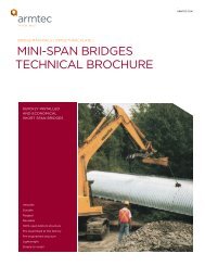
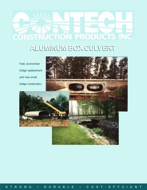
ALUMINUM BOX CULVERTFast, economicalbridge replacementand new smallbridge construction.S T R O N G • D U R A B L E • C O S T - E F F C I E N T
<strong>Aluminum</strong> <strong>Box</strong> <strong>Culvert</strong>The solution for small bridgesCONTECH <strong>Aluminum</strong> <strong>Box</strong> <strong>Culvert</strong>sare a practical and cost-efficientsolution for small bridge replacement.Lower installed costs result from<strong>Aluminum</strong> <strong>Box</strong> <strong>Culvert</strong>s being fasterand easier to install than cast-in-placeconcrete structures. There are noforms to set and remove, no delaysdue to curing time, large installationcrews are unnecessary, and nospecial equipment is needed. Also,no heavy cranes are required, as withprecast concrete structures.These wide span, low rise structuresare available in a large range ofstandard sizes (from 8’-9” span x2’-6” rise to 25’-5” span x 10’-2” rise)that permit a minimum cover of only17 inches for all spans.2
Faster installation means lower installed costClosing roads for bridge replacement causes extensive traffic detours, so minimizing installation time is critical.<strong>Aluminum</strong> <strong>Box</strong> <strong>Culvert</strong>s may be quickly erected in place and are usually ready to be backfilled in a matter of hours. Tofurther speed installation, <strong>Aluminum</strong> <strong>Box</strong> <strong>Culvert</strong>s may be completely assembled off site while the site is beingprepared. Light equipment may then be used to set the <strong>Aluminum</strong> <strong>Box</strong> <strong>Culvert</strong> in place.Lower job site unloading andassembly costs<strong>Aluminum</strong> plates and reinforcing ribs arrive at thejob site in strapped and nested bundles. Individualplates and ribs are generally light enough to behandled by one worker, while bundles can behandled with light-duty lifting equipment.Most structures can be assembled without liftingequipment.As a quality control to optimize field assemblyperformance, plates for each order are plantassembledand checked prior to shipment.Faster assembly – lessroad-closed timeStructures can be preassembled and lifted into placeall at once or in sections, allowing for stagedconstruction. If site conditions allow, structures canbe assembled in place.A qualified engineer should be engaged todetermine the most appropriate construction methodbased on specific site conditions.Assembly drawings and detailed assemblyinstructions are shipped with each structure.Pavement recommendationsCONTECH recommends that paved roadways beused above the structure to maintain minimumcover.Allowable cover (minimum and maximum) ismeasured from the exterior valley of the crown plateto the bottom of flexible pavement or from theexterior valley of the crown plate to the top of rigidpavement.Minimum cover is measured at the lowest fill areasubjected to possible wheel loads (typically at theroadway shoulder).The roadway surface must be well-maintained sothat long-term minimum cover heights are not lessthan those values recommended herein.Erosion protectionDuring construction, site runoff and stream flow must beadequately controlled to prevent disturbance of structure,bedding, and backfill.Erosion or washout of previously-placed soil support mustbe prevented to ensure that the structure maintains its loadcapacity.3
<strong>Aluminum</strong> <strong>Box</strong> <strong>Culvert</strong>s meet AASHTOand ASTM design standardsStructural designRibbed, corrugated <strong>Aluminum</strong> <strong>Box</strong> <strong>Culvert</strong>scombine the low profile shape of rigid boxculverts with the strength and economics offlexible structures.CONTECH <strong>Aluminum</strong> <strong>Box</strong> <strong>Culvert</strong>s aredesigned to meet or exceed AASHTO StandardSpecifications for Highway Bridge’s Section 12.8for HS 20 loading. Structures detailed on Page 6meet these requirements. Similar data forHS 25 loading is available. Moment capacitiesof <strong>Aluminum</strong> <strong>Box</strong> <strong>Culvert</strong>s have been confirmedusing finite element analysis.Like all structures, the box culvert’sdesign starts with the foundation. Footingcomponents, (see Pages 8 through 11), requirethat the foundation be able to support a footingbearing pressure of at least 4,000 pounds persquare foot. Foundation materials unable tosupport this load should be replaced.Guide rail usageThe FHWA has published allowable specialdesigns for guide rail usage over low coverstructures. For more information, contact yourlocal CONTECH representative.Hydraulic designHydraulic design nomographs for inlet and outletcontrol conditions are published in “HydraulicDesign of Highway <strong>Culvert</strong>s,” FHWA HDS-5.Additionally, the aluminum box culvert structuresshown in this catalog are included in the FHWAHY-8 hydraulics computer program. Hydraulicnomographs and structure geometric coordinatesfor use with HEC-RAS may be obtained from anyCONTECH Sales Office listed on the back cover.Field Testing at University of California research facility,Richmond, CA, to determine distribution of live load moments.Standard specificationsAll <strong>Aluminum</strong> <strong>Box</strong> <strong>Culvert</strong> material shall be manufactured inaccordance with: AASHTO M219 and ASTM B 864.AASHTO Standard Specification for Highway Bridges,Section 12.8 (design) and Section 26 (installation) are additionalreference specifications.Product assistanceComplete product details are available in CAD format. Consultyour CONTECH Sales Engineer to obtain this information.4
<strong>Aluminum</strong> is DurableAbrasion resistance<strong>Aluminum</strong>’s abrasion resistance has been proventhrough years of exposure to wet/dry abrasioncorrosioncycles. In normally abrasive runoffs,aluminum experiences minimum metal loss.The <strong>Aluminum</strong> Association presented a paper tothe Transportation Research Board in January 1969,reporting on more that 1,000 aluminum culverts*. (Anupdated report was presented in 1986**.) Both reportsincluded a method for predictingabrasion performance of aluminum corrugateddrainage pipe. Additional service life of structural pipecan be gained by increasing the metal thickness. Inmany cases, thickness increases for only the invertplates are sufficient.Corrosion resistanceThe aluminum alloys in aluminum structural plate havea proven history of excellent corrosion resistance.This is primarily due to a tenacious, inert oxidebarrier that naturally forms on the metal surface.The tough oxide barrier cannot be easilyremoved. If scratched or otherwise affected by anaggressive environment, the barrier heals itself. Theoxide barrier appears on the structure surface as agrayish white coating that builds up over time.Service-life expectancy studies on installedaluminum drainage products have been conductedsince the early 1960s by state and federal agencies.Based upon the performance and ongoinginspection of aluminum drainage structures firstinstalled in 1959, a minimum service life of 75 yearscan be predicted for .100”-thick aluminumstructural plate (pH between 4.0 and 9.0 andresistivity > 500 ohm-cm—protection from deicingsalts recommended).In addition, good performance may beexpected in seawater environments when thestructure is backfilled with a clean, granular material.All steel attachments, such as rebar and anchorbolts and rods, should be galvanized.If a proposed structure is expected to be installed in astream with high-velocity runoff and with heavy bed (invert)load (especially rocks with sharp corners), it is recommendedthat the <strong>Aluminum</strong> Association abrasion reports be consulted.Copies are available from CONTECH on request.When highly abrasive conditions are anticipated, archstructures on concrete footings can be used to avoidinvert damage.* “The mechanisms of Abrasion of <strong>Aluminum</strong> Alloy <strong>Culvert</strong>,Related Field Experiences, and a Method to Predict <strong>Culvert</strong>Performance”** “Abrasion Resistance of <strong>Aluminum</strong> <strong>Culvert</strong> Based onLong-Term Field Performance”CORROSIONRESISTANTThis aluminumstructural plate pipehas handled tidalocean waters underU.S. Highway 1 at theBay of Fundy in Mainesince 1966.ABRASIONRESISTANTIn an extremeexample of abrasiveflow, this CONTECH<strong>Aluminum</strong> <strong>Box</strong><strong>Culvert</strong> has beensubjected to heavybedload and highvelocity flow with nomeasurable effecton the corrugatedaluminum invert.5
Crown Rib (1)<strong>Aluminum</strong> is DurableHaunch Rib (1)9” x 2 1/2Corrugated Shell (2)Span “A”<strong>Box</strong> <strong>Culvert</strong> Shell Cross Section3 9/16”3”Type II RibType IV Rib2 1/2”2 1/2”<strong>Box</strong> <strong>Culvert</strong> Rib GeometryNotes1. All ribs are Type IV, except haunch ribs for Structures 1-39 which are Type II.2. Structure 1 is a one-plate shell. Structures 2-26 are two-plate shells. Structures 27-87 are three-plate shells3. In Shell Fill Height Table 1, the HG/CG designation indicates thickness or gage of haunch (HG) and crown (CG) plates as follows:2 = .125”, 3 = .150”, 4 = .175”, 5 = .200”, 6 = .225”, 7 = .250”.Example: 3/6 = .150” haunch and .225” crown plate thickness.The HRS/CRS designation indicates the rib spacing on the haunch (HRS) and crown (CRS) plates.Example: 27/9 = 27” o.c. haunch and 9” o.c. crown.4. Allowable cover (minimum and maximum) is measured from the outside valley of crown plate to bottom of flexiblepavement or from the outside valley of crown plate to top of rigid pavement. Minimum cover is measured at the lowestfill area subjected to possible wheel loads (typically at the roadway shoulder). The roadway surface must be maintainedto ensure minimum cover to prevent high-impact loads being imparted to structure. Maximum cover is measured athighest fill and/or pavement elevation.5. Select the structure with the lowest alphabet sub-designation and cover range that will include the actual minimum and maximum cover.Example: Structure 51-A is more economical than 51-B if the cover is between 3.0 and 4.5 feet.6. Shell Wt./Ft. shown is maximum handling weight and is based on heaviest component makeup for a specific span and rise combination.Weight per foot of shell includes plates, reinforcing ribs, rib splices, bolts and nuts.7. Total structure length can be any dimension, but whenever possible, it is recommended to work with a multiple of 4.5’ (net plate width).This practice usually results in lower total structure cost.Example: 50’ proposed structure /4.5’ = 11.1, nearest whole number is 11, therefore use 11 x 4.5’ = 49.5’ for total structure length. Whenordering a structure with headwalls on each end, total structure length should be a multiple of 9”.8. Shell data in Table 1 is designed for standard highway HS-20 wheel loads. See CONTECH brochure ALBC-102 for HS-25loading design information. Call a CONTECH Regional Office (listed on the back page) for design information on otherloadings.9. The maximum cover for <strong>Aluminum</strong> <strong>Box</strong> <strong>Culvert</strong>s with full inverts and footing pads should not exceed 4 feet. Special fullinvert and footing pad designs or slotted concrete footings can accommodate maximum covers to the limits shownin Table 1.7
AccessoriesVersatile CONTECH <strong>Aluminum</strong> <strong>Box</strong> <strong>Culvert</strong>s can be installed with various types of footings to meet most installationconditions. For structures installed where concrete is not readily available, or when forming and curing concretefootings or inverts is undesirable, a corrugated aluminum footing is available (see Pages 10 and 11).Full corrugated invert (see page 10)Standard corrugated invert is .100” aluminum plate.(Supplemental plates under receiving channels serve asfooting pads.) Standard 24” toewall is supplied for eachend of the structure. Greater heights may be supplied.As an alternate, a concrete toewall can be used.Standard hook bolts are also available to attach the invertto this type of toewall.When using a full invert, it is strongly recommendedthat steps be taken to avoid undermining the invert.**A minimum bearing capacity of 4,000 PSF is required when a full corrugatedinvert is used.Footing pads (see page 11)For sites where the stream bed is non-erodible, footingpads are generally most economical. If the stream bedpermits, footing pads should be buried 12 inches(minimum) to allow the soil inside to exert outwardpressure to balance the soil pressure resultingfrom backfilling.Concrete footingsWhen concrete footings or concrete inverts are required,the <strong>Aluminum</strong> <strong>Box</strong> <strong>Culvert</strong> may be placed in a receivingchannel or in a pre-formed slot.<strong>Aluminum</strong> <strong>Box</strong> <strong>Culvert</strong>Structures with.5N legs mayrequire awider slot toaccommodaterib and shell.GalvanizedHook BoltGroutConcrete FootingWith Receiving ChannelSlotted Concrete Footing8Geotextile is placed at the junction of shell and invertto prevent infiltration of backfill material.Flat sheet toewalls are provided for both ends ofstructures using a full corrugated aluminum invert.Toewalls help prevent stream flow from underminingthe structure.
Headwall packageThe standard headwall package features a headwall andusually two wingwalls. The headwall package results in afinished-looking structure, helps prevent scouring, andassists flow channelization (see Pages 12 and 13).Cast-in-place concrete or pre-cast modular block headwallsmay also be used.Note: The box culvert end treatment must be designedand built to prevent the loss of backfill material. Specialheadwall details may be required for a structure on a grade.This structure features a modular block headwall systemand is being used as a golf cart underpass.Cast-in-place concrete headwall.This <strong>Aluminum</strong> <strong>Box</strong> <strong>Culvert</strong> installation for the North Carolina DOT (Trenton, NC) employs aluminum headwallsand wingwalls.9
Invert Invert and and footing footing details detailsFULL INVERT - TABLE 2 (3) Structure Width Weight/Ft. (4)10Structure Width Weight/Ft. (4)Number “F”(N) (Lbs.)1 13 26.12 14 27.63 14 27.64 15 29.15 16 30.56 16 30.57 17 32.08 15 29.19 16 30.510 16 30.511 17 32.012 17 32.013 18 33.514 18 33.515 17 32.016 17 32.017 18 33.518 18 33.519 19 35.020 19 35.021 19 35.022 19 35.023 19 35.024 20 37.925 20 37.926 20 43.727 21 45.228 21 45.229 21 45.230 22 46.731 22 46.732 22 46.733 22 46.734 22 46.735 23 48.236 23 48.237 23 48.238 23 48.239 23 48.240 26 55.241 26 55.242 27 56.643 27 56.644 28 58.145 28 58.146 29 59.647 27 56.648 28 58.149 28 58.150 29 59.651 29 59.652 29 61.553 30 63.054 29 61.555 29 61.5GeotextileReceiving ChannelReinforcing RibCorrugated ShellScallop PlateSupplemental Plate (5) 9 x 2 1/2” Corrugated Invert (5,7)Span “A” (See “A” on Pages 6 & 7)ToewallFull Invert Width “F” (See Table 2)<strong>Aluminum</strong> Full Invert Option (2,3,5,6)Note: Flat sheet toewalls are available only for structures having afull corrugated aluminum invert (see Page 8)Number “F”(N) (Lbs.)56 30 63.057 30 63.058 30 63.059 31 64.560 31 64.561 30 63.062 31 64.563 31 66.464 31 66.465 32 67.966 32 67.967 32 67.968 32 67.969 32 67.970 32 67.971 33 69.472 33 69.473 33 69.474 33 69.475 33 71.376 34 72.877 34 72.878 34 72.879 34 72.880 34 72.881 34 72.882 35 78.883 35 78.884 35 78.885 36 80.386 36 80.387 36 80.33/4” Bolts @ 19 1/4” o.c.3”9” x 2 1/2” Corrugated Invert3 1/2” x 3” AngleWidth“G”<strong>Aluminum</strong> FlatSheet ToewallDetailGeotextileNotes1. N = 9.625" or 9 5 / 8“. Use N as a conversion factor.For example, for structure No 1, Width “F” is 13 x N,or 125.13".2. Minimum allowable soil bearing pressure is4,000 Lbs./Sq. Ft. for structures and detailsshown in this catalog. This appliesspecifically for width “G” below thereceiving channel. Other conditions can beaccommodated. Contact a CONTECH RegionalOffice for more information.3. The maximum cover for <strong>Aluminum</strong> <strong>Box</strong><strong>Culvert</strong>s with full inverts and footing padsshould not exceed 4 feet. Special full invertand footing pad designs or slotted concretefootings can accommodate maximum coversto the limits shown in Table 1, Page 6.4. Weight per foot of full invert includes receivingchannels, scallop plates, nuts and bolts, and allplates.5. Full invert plates are .100" thick. When reactions tothe invert require additional thickness, supplementalplates of the thickness and width listed in Table 2are furnished to bolt between the full invert and thereceiving channel.6. Invert widths 20N and greater are two-piece.7. Invert plates must not be overlapped on adjacentstructures unless appropriate design modificationsare incorporated.
FOOTING PADS - Table 3 (3)Structure Plate Width Weight/Ft. (4)Number Thickness (In.) “G” (N) (Lbs.)Reinforcing RibCorrugated Shell1 0.100 2 11.92 0.100 2 11.93 0.100 2 11.94 0.100 2 11.95 0.100 2 11.96 0.100 2 11.97 0.100 2 11.98 0.100 2 11.99 0.100 2 11.910 0.100 2 11.911 0.100 2 11.912 0.100 2 11.913 0.100 2 11.914 0.100 2 11.915 0.100 2 11.916 0.100 2 11.917 0.100 2 11.918 0.100 2 11.919 0.100 2 11.920 0.100 2 11.921 0.100 2 11.922 0.100 2 11.923 0.100 2 11.924 0.100 2 11.925 0.100 2 11.926 0.125 2 13.227 0.125 2 13.228 0.125 2 13.229 0.125 2 13.230 0.125 2 13.231 0.125 2 13.232 0.125 2 13.233 0.125 2 13.234 0.125 2 13.235 0.125 2 13.236 0.125 2 13.237 0.125 2 13.238 0.125 2 13.239 0.125 2 13.240 0.200 3 22.241 0.200 3 22.242 0.200 3 22.243 0.200 3 22.244 0.200 3 22.245 0.200 3 22.246 0.200 3 22.247 0.200 3 22.248 0.200 3 22.249 0.200 3 22.250 0.200 3 22.251 0.200 3 22.252 0.225 3 24.153 0.225 3 24.154 0.225 3 24.155 0.225 3 24.1Width “G”Receiving ChannelFooting Pad (5,6) (See Table 3)Place Footing BelowAnticipated Scour<strong>Aluminum</strong> Footing Pad Option (2,3)Structure Plate Width Weight/Ft. (4)Number Thickness (In.) “G” (N) (Lbs.)56 0.225 3 24.157 0.225 3 24.158 0.225 3 24.159 0.225 3 24.160 0.225 3 24.161 0.225 3 24.162 0.225 3 24.163 0.250 3 26.064 0.250 3 26.065 0.250 3 26.066 0.250 3 26.067 0.250 3 26.068 0.250 3 26.069 0.250 3 26.070 0.250 3 26.071 0.250 3 26.072 0.250 3 26.073 0.250 3 26.074 0.250 3 26.075 0.275 3 28.076 0.275 3 28.077 0.275 3 28.078 0.275 3 28.079 0.275 3 28.080 0.275 3 28.081 0.275 3 28.082 0.300 3.5 33.883 0.300 3.5 33.884 0.300 3.5 33.885 0.300 3.5 33.886 0.300 3.5 33.887 0.300 3.5 33.8Structure with aluminum footing pads.Notes1. N = 9.625" or 9 5 / 8“. Use N as aconversion factor. For example, forStructure No 1, Width “G” is 2 x N,or “19.25”.2. Minimum allowable soil bearingpressure is 4,000 Lbs./Sq. Ft. forstructures and details shown inthis catalog. This appliesspecifically for width “G” belowthe footing pad. Other conditionscan be accommodated. Contact aCONTECH Regional Office formore information.3. The maximum cover for<strong>Aluminum</strong> <strong>Box</strong> <strong>Culvert</strong>s with fullinverts and footing pads shouldnot exceed 4 feet. Special fullinvert and footing pad designsor slotted concrete footings canaccommodate maximum coversto the limits shown in Table 1,Page 6.4. Weight per foot of footing padsincludes receiving channels,scallop plates, nuts and bolts, andplates.5. When the thickness listed is greaterthan .250”, the footing pads will betwo or more pieces equaling thecomposite thickness required. SeeTable 3.6. Footing pads must not beoverlapped on adjacent structuresunless appropriate designmodifications are incorporated.11
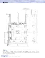
Headwall Details1’-6” Structure No. 1-392’-0” Structure No. 40-87(Additional wale beams may berequired if these values are exceeded.)Vertical JointHeadwall width (90 to structure )Wingwall (3,4)Wing Panel (2) End Panel (2) Center PanelsEnd Panel (2)Corner PanelWing Panel3”Headwall CapElbow Cap (3,4)WaleBeamHeight (2)(See Table 4)Filler reinforcing rib to bepunched and fitted to boxculvert and headwall(each side if required).Anchor Rod (Typical)Rise “B”Reinforcing RibWale Beam<strong>Box</strong> <strong>Culvert</strong>Invert PlateFooting Pad orConcrete Footing (9)Span “A”Panel Entrenchment (2)(Approx. 2’)Typical Headwall Elevation<strong>Aluminum</strong> deadman anchor required in center ofeach wing panel and corner panel. (8)Crown Rib<strong>Box</strong> <strong>Culvert</strong> ShellAnchor RodHeadwall anchor rod tostructure from cap atcenter of each panel.(see Section A-A)(4’-6” Typical)Wing PanelPlan at Topof Headwall CapElbow Cap (3,4)Wale Beamof box culvertHeadwall CapPlan ViewNotes – Headwall1. All panels are fabricated from aluminum structural plate as specified in ASTM B 746.2. Height of headwall listed in table 4 permits approximately 24” entrenchment depth below the invert.All headwall panels must be trenched into existing ground.3. Horizontal rotation on the wingwall should not exceed 90 o .4. The top of a headwall and its wingwall is always horizontal, unless beveled wingwalls are required.5. Standard headwalls shown are for vertical orientation only.6. If side slope is flatter than 2:1, a double tieback assembly is required for each deadman.7. Standard headwalls are shown. HS 20 wheel loads must be kept a minimum distance of 36” fromthe wall face. Special headwall packages can be fabricated to meet other loading requirements.8. For details on single and dual deadmen anchors, refer to CONTECH Drawings #1009423 and1009423C.9. Structures on concrete footings with headwalls require field modification of the headwall plates to fitaround the footings.12
HEADWALL - TABLE 4. See notes on page 12.No. Width Height No. Width HeightWith the headwall assembly complete, this structure is readyfor backfill.Wingwall with deadman anchors.Field drilland boltAnchor RodAttachment PieceHeadwall CapAnchor RodGeotextileCorrugated CrownPlateSection A-A<strong>Aluminum</strong> BracingAssemblyCorrugatedHeadwallField drilland boltReinforcingRib1 13' - 6" 6'-0" 46 22'-6" 12'-7"2 13' - 6" 7'-0" 47 24'-0" 8'-7"3 13' - 6" 7'-10" 48 24'-0" 9'-5"4 13' - 6" 8'-7" 49 24'-0" 10'-2"5 13' - 6" 9'-5" 50 24'-0" 11'-0"6 13' - 6" 10'-2" 51 24'-0" 11'-10"7 13' - 6" 11'-0" 52 24'-0" 12'-7"8 15' - 0" 7'-0" 53 24'-0" 13'-5"9 15' - 0" 7'-10" 54 25'-6" 8'-7"10 15' - 0" 8'-7" 55 25'-6" 9'-5"11 15' - 0" 9'-5" 56 25'-6" 10'-2"12 15' - 0" 10'-2" 57 25'6" 11'-0"13 15' - 0" 11'-0" 58 25'-6" 11'-10"14 15' - 0" 11'-10" 59 25'-6" 12'-7"15 16' - 6" 7'-0" 60 25'-6" 13'-5"16 16' - 6" 7'-10" 61 27'-0" 9'-5"17 16' - 6" 8'-7" 62 27'-0" 10'-2"18 16' - 6" 9'-5" 63 27'-0" 11'-0"19 16' - 6" 10'-2" 64 27'-0" 11'-10"20 16' - 6" 11'-0" 65 27'-0" 12'-7"21 18' - 0" 7'-0" 66 27'-0" 13'-5"22 18' - 0" 7'-0" 67 27'-0" 14'-3"23 18' - 0" 8'-7" 68 28'-6" 9'-5"24 18' - 0" 9'-5" 69 28'-6" 10'-2"25 18' - 0" 10'-2" 70 28'-6" 11'-0"26 19' - 6" 7’-0" 71 28'-6" 11'-10"27 19' - 6" 7'-10" 72 28'-6" 12'-7"28 19' - 6" 8'-7" 73 28'-6" 13'-5"29 19' - 6" 9'-5" 74 28'-6" 14'-3"30 19' - 6" 10'-2" 75 30'-0" 9'-5"31 19' - 6" 11'-0" 76 30'-0" 10'-2"32 19' - 6" 11'-10" 77 30'-0" 11'-0"33 21'- 0" 7'-10" 78 30'-0" 11'-10"34 21'- 0" 8'-7" 79 30'-0" 12'-7"35 21'- 0" 9'-5" 80 30'-0" 13'-5"36 21'- 0" 10'-2" 81 30'-0" 14'-3"37 21'- 0" 11'-0" 82 31'-6" 10'-2"38 21'- 0" 11'-10" 83 31'-6" 11'-0"39 21'- 0" 12'-7" 84 31'-6" 11'-10"40 22' - 6" 7'-10" 85 31'-6" 12'-7"41 22' - 6" 8'-7" 86 31'-6" 13'-5"42 22' - 6" 9'-5" 87 31'-6" 14'-3"43 22' - 6" 10'-2"44 22' - 6" 11'-0"45 22' - 6" 11'-10"When headwalls are ordered for both ends,the length of structure must be a multiple of 9”.13
Specifications and General InformationScopeThis specification covers the manufactureand installation of the aluminum boxculvert structure detailed in the plans.MaterialThe aluminum box culvert shall consist ofplates, ribs, and appurtenant items asshown on the plans and shall conform tothe requirements of ASTM B 864 andAASHTO M219. Plate thicknesses, ribspacings, end treatment, and type ofinvert and foundation shall be as indicatedon the plans.Bolts and nuts shall conform to the requirementsof ASTM A 307 or ASTM A 449and shall be galvanized in accordance withASTM A 153.AssemblyThe box culvert shall be assembled inaccordance with shop drawings providedby the manufacturer and per themanufacturer’s recommendations. Boltsshall be tightened using an applied torquebetween 100 and 150 foot-pounds.Simple and fast assembly of a box culvert is beingachieved with its lightweight aluminum components.14
InstallationThe box culvert shall be installed in accordance withthe plans and specifications, the manufacturer’srecommendations, and the AASHTO StandardSpecification for Highway Bridges, Section 26(Division II).BeddingThe bedding should be constructed to a uniform lineand grade using material outlined in the backfillsection. For structures with full inverts or footing pads,the foundation must be capable of providing a bearingcapacity of at least two tons per square foot.BackfillThe backfill material should be free of rocks, frozenlumps, and foreign material that could cause hard spotsor decompose to create voids. Backfill material shouldbe well graded granular material that meets therequirements of AASHTO M145 for soilclassifications A-1, A-3,A-2-4, or A-2-5. Backfill must be placed symmetrically oneach side of the structure in 6-inch to 8-inch loose lifts.Each lift is to be compacted to a minimum of 90 percentdensity per AASHTO T180.The structure must be protected from unbalancedloads and from any structural loads or hydraulic forcesthat might bend or distort the unsupported ends of thestructure.Refer to ASTM B 789 installation specification.Standard box culverts designs cannot safely carryconstruction vehicle traffic in excess of highway loadlimits. While additional cover may be used in someinstances to handle temporary construction vehicle loads,cover should not exceed the maximum allowable cover forthe specific box culvert design.During backfilling, only small tracked vehicles (D-4or smaller) should be near the structure as fill progressesabove the crown and to finished grade.15
An answer to your site develpment problemsThere is a size and type of CONTECH product to help solve many civil engineering site development problems.You can use these products with complete confidence in their strength, durability, and economy.They have been tested and proven by three-quarters of a century of research and practical field experience.HEL-COR Corrugated Steel Pipe and CORLIX Corrugated<strong>Aluminum</strong> Pipe…These products are designed for use asdrainage culverts, storm sewers, stream enclosures, andunderground conduits for highway, railway, industrial, andmunicipal applications. They are supplied in a variety of liningsand coatings to meet specific durability and hydraulicrequirements.HEL-COR CL Pipe…Concrete-lined for top flow capacity plusproven strength of corrugated steel design.End Sections…A modern end finish for culverts and seweroutfalls, either pipe or pipe-arch structures in steel oraluminum.ULTRA FLO Storm Sewer Pipe…For improved hydraulic capacityand light weight for storm sewers.Slotted Drain…An efficient system for highways, parking lots, orother surface drainage involving only narrow slots on thesurface.Perforated Pipe…For subdrainage applications, such asairports, highways, and railroads. Available in metal and plasticpipe.HEL-COR Pile Shell…For foundations under buildings andbridges.MULTI-PLATE Pipe, Pipe-Arch, and Arch…For bridges, streamenclosures, and storm sewers.Bin-Type Retaining Walls…For unstable slopes, limited rightsof-way,shore and bank protection.Liner Plate…For constructing new utility tunnels and reliningstructures under existing highways and railroads.Bridge-Plank…For reflooring bridges and for new bridgeconstruction.Metric Sheeting…For trenches, cofferdams, shore protection,and cutoff walls.A-2000 PVC Pipe…Profiled wall construction and smoothinterior for sanitary collector sewers and storm sewers. MeetsASTM F 949.D-2000(M304) PVC Storm Sewer Pipe…Profiled wallconstruction and smooth interior for sanitary collector sewersand storm sewers. Meets ASTM F 949.A2 Liner Pipe…For sliplining storm and sanitary sewers whereminimal site excavation is desirable.ABS and PVC TRUSS PIPE…Combines strength, stiffness, jointintegrity, and economy for gravity-flow sanitary sewers.Meets ASTM D 2680.SUPER-SPAN Structures…Economically and aestheticallyadvantageous for new and replacement bridges.<strong>Box</strong> <strong>Culvert</strong>s…For maximum water flow under minimumheadroom. <strong>Aluminum</strong>’s light weight means easier installation.Geosynthetics…TENSAR Geogrids for soil reinforcement, basestabilization, slope reinforcement, and retaining walls.CONTECH Woven and Nonwovern Geotextiles for drainage,separation,filtration, and stabilization. STRIPDRAIN for highwayedge drains and building foundation drainage. CONTECHERO-MAT and Contech Excelsior Mat for erosion control andvegetation reinforcement. PavePrep to control/retardreflective cracking in pavements.CONTECH CONSTRUCTION PRODUCTS INC. • P.O. BOX 800 • MIDDLETOWN, OHIO 45042Regional Offices are in the following locations:Arkansas (North Little Rock) 72113 10100 Maumale Blvd. 501-758-1985California (San Bernardino) 92408 1845 S. Business Center Dr. Suite 130 909-885-8800Colorado (Wheat Ridge) 80033 4891 Independence St., Suite 195 303-431-8999Georgia (Norcross) 30071 6825 Jimmy Carter Blvd., Suite 1800 770-409-0814Illinois (Oak Brook) 60523 1200 Harger Road, Suite 707 630-573-1110Indiana (Indianapolis) 46250 7164 Graham Rpoad, Suite 120 317-842-7766Kansas (Topeka) 66614-2466 5883 S.W. 29th St. 785-273-5950Massachusetts (Palmer) 01069 Fenton St. 413-283-7611North Carolina (Raleigh) 27609 4700 Homewood Court, Suite 108 919-781-8540Texas (Irving) 75062 4425 West Airport Freeway, Suite 340 972-659-0828Sales Offices are in principal cities.Visit us at www. contech-cpi.comNOTHING IN THIS CATALOG SHOULD IN ANY WAY BE CONSTRUED AS AN EXPRESSWARRANTY OR AS EXTENDING TO THE READER OR BUYER ANY IMPLIEDWARRANTY INCLUDING BUT NOT LIMITED TO THE IMPLIED WARRANTIES OFMERCHANT ABILITY OR FITNESS FOR ANY PARTICULAR PURPOSE.Specifications and data referring to mechanical and physical properties or chemicalanalyses relate solely to tests performed at the time of manufacture on specimensobtained from specific locations of the products in accordance with prescribed samplingprocedures. For specific terms and conditions of sale, refer to standard CONTECHdocuments.CONTECH, CORLIX, HEL-COR, MULTI-PLATE, PavePrep, TRUSS PIPE, and ULTRA FLOare registered trademarks of CONTECH CONSTRUCTION PRODUCTS INC. A2 LinerPipe, A-2000, D2000, Slotted Drain, and SUPER-SPAN are trademarks of CONTECHCONSTRUCTION PRODUCTS INC. STRIPDRAIN is a trademark of HITEK LTD.TENSAR is a registered trademark. ERO-MAT is a trademark of Verdyol.© 1999, CONTECH CONSTRUCTION PRODUCTS INC., Middletown, Ohio.