SUBMITTAL DATA gas-fired unit heaters models PD & BD 6-422.2
SUBMITTAL DATA gas-fired unit heaters models PD & BD 6-422.2
SUBMITTAL DATA gas-fired unit heaters models PD & BD 6-422.2

Create successful ePaper yourself
Turn your PDF publications into a flip-book with our unique Google optimized e-Paper software.
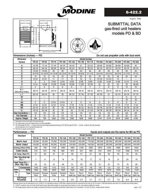
6-<strong>422.2</strong>August, 1999AHJ VENT PIPEKAAEBWFXKCG<strong>SUBMITTAL</strong> <strong>DATA</strong><strong>gas</strong>-<strong>fired</strong> <strong>unit</strong> <strong>heaters</strong><strong>models</strong> <strong>PD</strong> & <strong>BD</strong>B<strong>BD</strong> (OPENING)EELLDimensions (inches) — <strong>PD</strong>DimensionStandardL(MIN. DISTANCE TO WALL)Model NumberModel NumberDo not use propeller <strong>unit</strong>s with duct work.Symbol <strong>PD</strong> 30 <strong>PD</strong> 50 <strong>PD</strong> 75 <strong>PD</strong> 100 <strong>PD</strong> 125 <strong>PD</strong> 150 <strong>PD</strong> 175 <strong>PD</strong> 200 <strong>PD</strong> 250 <strong>PD</strong> 300 <strong>PD</strong> 350 <strong>PD</strong> 400A 12-7/8 17-1/4 17-1/4 19-1/4 19-1/4 21 23-1/2 25-5/8 25-5/8 28-5/8 33-5/8 40B 24-1/4 24-1/4 28-3/4 28-3/4 35-1/4 35-1/4 35-1/4 40-1/4 40-1/4 40-1/4 40-1/4 40-1/4C 14-3/4 14-3/4 20 20 22 22 22 25 25 25 25 25D 10-7/16 14-13/16 14-13/16 16-13/16 16-13/16 18-9/16 21-1/16 23-3/16 23-3/16 26-3/16 31-3/16 37-1/2E 13 13 16 16 20 20 20 24 24 24 24 24F 9-1/4 9-1/4 11 11 12 12 12 13-1/2 13-1/2 14 – –G 2 2 2-3/4 2-3/4 3-5/8 3-5/8 3-5/8 4-3/8 4-3/8 4-3/8 4-1/4 4-1/4H 9-1/4 13-5/8 13-5/8 15-5/8 15-5/8 17-3/8 19-7/8 22 22 25 30 36-3/8J ➀ 3 4 5 6 6 7 7 7 8 9 10 10K ➂(Mounting Holes)3/8-16 3/8-16 3/8-16 3/8-16 3/8-16 3/8-16 3/8-16 3/8-16 3/8-16 3/8-16 3/8-16 3/8-16L ➃ 28-1/4 28-1/4 36 36 36-1/2 37-1/8 37-1/8 40-7/8 41 42-1/4 42-1/4 47-1/4W – – – – – – – – – – 5 5X – – – – – – – – – – 16 16AA 5 5 6-1/4 6-1/4 8 8 8 9 9 9 9 9BB 6-1/4 6-1/4 6-1/2 6-1/2 7-1/4 7-1/4 7-1/4 7-1/4 7-1/4 7-1/4 7-1/4 7-1/4EE 22-1/4 22-1/4 29 29 30-1/2 30-1/2 30-1/2 32-7/8 32-7/8 32-7/8 32-7/8 32-7/8LL 19-1/2 20-1/8 30 30 30 31-1/8 31-1/8 34-7/8 34-7/8 36-1/4 36-1/4 41-1/4Gas Connections ➁ 1/2 1/2 1/2 1/2 1/2 1/2 1/2 1/2 1/2 1/2 3/4 3/4Fan Diameter 9 12 12 14 14 16 18 20 20 22 22 24Approx. Weight 58# 72# 102# 116# 152# 162# 169# 231# 231# 261# 330# 410#➀ Diameter of round vent pipe to fit oval opening.➁ For natural <strong>gas</strong>; may vary depending on control availability.➂ <strong>PD</strong> 30 through <strong>PD</strong> 300 — 2 holes (and the level hanging adjustment feature). <strong>PD</strong> 350 through <strong>PD</strong> 400 — 4 holes. Listed is the hole diameterand threads per inch to accept threaded rod.➃ Dimension equals overall plus 6".Performance — <strong>PD</strong>Inputs and outputs are the same for <strong>BD</strong> as <strong>PD</strong><strong>PD</strong> 30 <strong>PD</strong> 50 <strong>PD</strong> 75 <strong>PD</strong> 100 <strong>PD</strong> 125 <strong>PD</strong> 150 <strong>PD</strong> 175 <strong>PD</strong> 200 <strong>PD</strong> 250 <strong>PD</strong> 300 <strong>PD</strong> 350 <strong>PD</strong> 400Btu/Hr. Input 30,000 50,000 75,000 100,000 125,000 150,000 175,000 200,000 250,000 300,000 350,000 400,000Btu/Hr. Output 24,000 40,000 60,000 80,000 100,000 120,000 140,000 160,000 200,000 240,000 280,000 320,000Entering Airflow (CFM) 440 740 1100 1460 1850 2180 2550 2870 3700 4460 4870 5440Outlet Velocity 515 610 736 860 870 931 959 819 1053 1123 1068 1016Air Temp. Rise (°F) 51 50 51 51 50 51 51 52 50 50 53 54Max. Mounting Hgt.(Ft.) ➀ 7 9 12 14 14 16 17 15 19 21 20 19Heat Throw (Ft.) ➀(Max. Mtg. Hgt.) 25 33 41 49 51 55 59 51 67 74 70 69MotorData➁Horsepower 1/40 1/40 1/12 1/12 1/8 1/8 1/6 1/6 1/3 1/2 3/4 3/4RPM 1550 1550 1625 1625 1625 1625 1075 1075 1075 1075 1125 1125Type Shaded Shaded Shaded Shaded Perm. Perm. Perm. Perm. Perm. Perm. Perm. Perm.Pole Pole Pole Pole Split Cap. Split Cap. Split Cap. Split Cap. Split Cap. Split Cap. Split Cap. Split Cap.Unit PowerRe’q (amps) 1.3 1.3 1.9 1.9 2.6 2.6 3.1 3.1 5.7 7.8 8.4 8.4Ratings shown are for elevations up to 2,000 ft. For elevations above 2,000 feet, ratings should be reduced at the rate of 4% for each 1,000 feet above sea level. (In Canada see rating plate.)➀ At 65°F ambient and <strong>unit</strong> <strong>fired</strong> at full-rated input. Mounting height as measured from bottom of <strong>unit</strong>, and without deflector hoods.➁ All single phase motors are totally enclosed and thermal overload protected. Data listed is for standard 115-volt, 60 hertz, single-phase motors.page 1 of 2
6-<strong>422.2</strong> — <strong>SUBMITTAL</strong> <strong>DATA</strong> MODELS <strong>PD</strong>/<strong>BD</strong>AHCFNEEJ VENT PIPEKWXSP4-5/8''AAGOEBKRxTQxVB<strong>BD</strong> (OPENING)M (APPROX.)L (MIN. DISTANCE TO WALL)BLOWERENCLOSURE(OPTIONAL)L (MIN. DISTANCE TO WALL)FILTER RACK(OPTIONAL)Dimensions (inches) — <strong>BD</strong>DimensionModel NumberSymbol <strong>BD</strong> 50 <strong>BD</strong> 75 <strong>BD</strong> 100 <strong>BD</strong> 125 <strong>BD</strong> 150 <strong>BD</strong> 175 <strong>BD</strong> 200 <strong>BD</strong> 250 <strong>BD</strong> 300 <strong>BD</strong> 350 <strong>BD</strong> 400A 17-1/4 17-1/4 19-1/4 19-1/4 21 23-1/2 25-5/8 25-5/8 28-5/8 33-5/8 40B 24-1/4 28-3/4 28-3/4 35-1/4 35-1/4 35-1/4 40-1/4 40-1/4 40-1/4 40-1/4 40-1/4C 14-3/4 20 20 22 22 22 25 25 25 25 25D 14-13/16 14-13/16 16-13/16 16-13/16 18-9/16 21-1/16 23-3/16 23-3/16 26-3/16 31-3/16 37-1/2E 13 16 16 20 20 20 24 24 24 24 24F 9-1/4 11 11 12 12 12 13-1/2 13-1/2 14 – –G 2 2-3/4 2-3/4 3-5/8 3-5/8 3-5/8 4-3/8 4-3/8 4-3/8 4-1/4 4-1/4H 13-5/8 13-5/8 15-5/8 15-5/8 17-3/8 19-7/8 22 22 25 30 36-3/8J ➀ 4 5 6 6 7 7 7 8 9 10 10K Mounting Holes ➃ 3/8-16 3/8-16 3/8-16 3/8-16 3/8-16 3/8-16 3/8-16 3/8-16 3/8-16 3/8-16 3/8-16L w/ Blwr Encl & Filt Rk 47-5/8 52-5/8 55-5/8 51-5/8 62-5/8 62-5/8 69-5/8 69-5/8 69-5/8 69-5/8 69-5/8L w/o Blwr Encl & Filt Rk 38 43-1/8 45-3/4 49-7/8 53-1/8 53-1/8 61 61 61 61 65M ➂ 32 37-1/8 39-3/4 43-7/8 47-1/8 47-1/8 55 55 55 55 59N ➄ 11-3/4 14-7/8 17-5/8 18-5/8 21-1/2 21-1/2 25-7/16 25-7/16 24-15/16 17-15/16 22O 4-1/2 5-3/4 5-3/4 7-1/2 7-1/4 7-1/4 8-1/2 8-1/2 8-1/2 8-1/2 8-1/2P 22 22 25 25 30 30 34 34 34 34 34Q Blower Encl Ht 14-1/8 17-1/8 17-1/8 21-3/8 21-3/8 21-3/8 25-1/8 25-1/8 25-1/8 25-1/8 25-1/8R Inlet Duct Height 15-3/4 15-3/4 15-3/4 20 20 20 23-3/4 23-3/4 23-3/4 23-3/4 23-3/4S Center to CenterBlower Mtg. Holes 10-15/16 13-15/16 18-7/16 18-7/16 17-5/16 17-3/8 20-3/8 20-3/8 20-3/8 20-3/8 20-3/8T Inlet Duct Width 16 16 19-3/4 19-3/4 27-1/2 27-1/2 32-3/4 32-3/4 32-3/4 42-7/8 42-7/8V Blower Encl Width 17-1/2 17-1/2 21-1/4 21-1/4 29 29 34-1/4 34-1/4 34-1/4 44-3/8 44-3/8W – – – – – – – – – 5 5X – – – – – – – – – 16 16AA 5 6-1/4 6-1/4 8 8 8 9 9 9 9 9BB 6-1/4 6-1/2 6-1/2 7-1/4 7-1/4 7-1/4 7-1/4 7-1/4 7-1/4 7-1/4 7-1/4EE 41-3/8 46-5/8 49-5/8 56-5/8 56-5/8 56-5/8 63-5/8 63-5/8 63-5/8 63-5/8 63-5/8Gas Connections ➁ 1/2 1/2 1/2 1/2 1/2 1/2 1/2 1/2 1/2 3/4 3/4Std. Mtr. Sheave Dia. ➅ 3 3 3 3 3 3 3 3 3 3 4-1/2Std. Blower Sheave Dia. 8 10 8 7 11 7 14 10 7 6 10Blower Wheel Diameter 8 8 9 9 13 13 15 15 15 15 15Approx. Weight 116# 146# 158# 205# 215# 231# 307# 307# 331# 420# 490#➀ Diameter of round vent pipe to fit oval opening.➁ For natural <strong>gas</strong>; may vary depending on control availability.➂ This is an approximate dimension for standard motors, allow 3" for sheave and optional motors.➃ <strong>BD</strong> 50 thru <strong>BD</strong> 300 — 4 holes (2 on blower and 2 on <strong>unit</strong>).<strong>BD</strong> 350 and <strong>BD</strong> 400 — 6 holes (2 on blower and 4 on <strong>unit</strong>).Listed is the hole diameter and threads per inch to accept threaded rod.Standard Blower Motor Data — <strong>BD</strong> ➀MotorDataStandard➄ Distance between mounting hole in <strong>unit</strong> casing and mounting hole on blower. On the <strong>BD</strong> 350 and<strong>BD</strong> 400, the distance is from rear mounting hole in casing to the mounting hole on blower.➅ Motor pulley is adjustable.NOTE: Mounting heights and throws for <strong>BD</strong> <strong>models</strong>, without ductwork or nozzles, and at a cfmyielding a 55° temperature rise are the same as those listed for equivalent size <strong>PD</strong> <strong>unit</strong>s.Model Number<strong>BD</strong> 50 <strong>BD</strong> 75 <strong>BD</strong> 100 <strong>BD</strong> 125 <strong>BD</strong> 150 <strong>BD</strong> 175 <strong>BD</strong> 200 <strong>BD</strong> 250 <strong>BD</strong> 300 <strong>BD</strong> 350 <strong>BD</strong> 400Horsepower 1/4 1/4 1/4 1/4 1/4 1/3 1/4 1/3 3/4 1 1-1/2RPM 1725 1725 1725 1725 1725 1725 1725 1725 1725 1725 1725TypeSplitPhaseSplitPhaseSplitPhaseSplitPhaseSplitPhaseSplitPhaseSplitPhaseSplitPhaseSplitPhaseCap.StartCap.StartUnit PowerRe’q (amps) 5.7 5.7 5.7 5.7 5.7 5.3 5.7 5.3 11.3 13.7 15.7➀ Data listed is for standard 115-volt, 60-Hertz, single-phase motors.page 2 of 2Commercial HVAC&R Division • Modine Manufacturing Company • 1500 DeKoven Avenue • Racine, Wisconsin 53403-2552Phone: 1-800-828-4328 (HEAT) • Fax: 414-636-1665 • E-mail: hvac&r@modine.com© Modine Manufacturing Company 1999 C7/99 - 4M Litho in USA