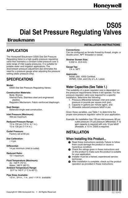
DS05 Dial Set Pressure Regulating Valves - Wolseley Express
DS05 Dial Set Pressure Regulating Valves - Wolseley Express
DS05 Dial Set Pressure Regulating Valves - Wolseley Express

Create successful ePaper yourself
Turn your PDF publications into a flip-book with our unique Google optimized e-Paper software.
<strong>DS05</strong><strong>Dial</strong> <strong>Set</strong> <strong>Pressure</strong> <strong>Regulating</strong> <strong>Valves</strong>APPLICATIONThe Honeywell Braukmann <strong>DS05</strong> <strong>Dial</strong> <strong>Set</strong> <strong>Pressure</strong><strong>Regulating</strong> Valve is a high quality pressure regulatingvalve that maintains a constant outlet pressure over awide range of inlet supply pressures. It is suitable forpotable water and irrigation applications. Thedownstream pressure adjustment dial eliminates theneed for a pressure gauge when adjusting the pressuresetting (static pressure only).SPECIFICATIONSModel:<strong>DS05</strong> <strong>Dial</strong> <strong>Set</strong> <strong>Pressure</strong> <strong>Regulating</strong> <strong>Valves</strong>.Construction Materials:Body: Bronze.Internal Parts: Stainless steel and engineeredplastics.Regulator Mechanism: Fabric-reinforced diaphragm.Seat Design:Balanced single seat construction.Inlet <strong>Pressure</strong> (Maximum):400 psi maximum.Reduced <strong>Pressure</strong> Range:15 to 150 psi (1/2 in. to 1 in.).15 to 130 psi (1-1/4 in.).Outlet <strong>Pressure</strong>:Factory set at 60 psi.<strong>Dial</strong> Calibration:± 4 psi.Differential:14 psi minimum (inlet to outlet).Reduced Ratio:10:1 maximum.Fluid Temperature (Maximum):Air: 158°F (70°C).Water: 180°F (82°C).Ambient Temperature Range:33°F to 140°F (1°C to 60°C).INSTALLATION INSTRUCTIONSConnections:Can be configured as female thread-by-thread, single- ordouble-union, NPT threaded or sweat.Strainer Screen Size:0.032 in. (0.8 mm).Gauge Tap:1/4 in. NPT.Approvals:ASSE (Std. 1003) Certified.IAPMO, CSA, and City of L.A. Listed.Water Capacities (See Table 1.)The suitability of a given regulator size is dependent onthe pressure requirements where it will operate. For thepressure regulator valve size required for a specificinstallation, determine the following:1. <strong>Pressure</strong> differential between inlet and outletpressure in pounds per square inch (psi),2. Capacity in gallons per minute (gpm), and3. Allowable reduced pressure falloff in psi.Given these variables, use Table 1 to determine theproper size pressure regulator valve for your application.Example: An installation has 135 psi inlet pressure, 60 psioutlet pressure (75 psi pressure differential). If 12gpm capacity is required with only 10 psi falloffallowable, a 1/2 in. <strong>DS05</strong> is required.INSTALLATIONWhen Installing this Product... Read these instructions carefully. Failure to followthem could damage the product or cause ahazardous condition. Check the ratings given in these instructions andon the product to make sure the product is suitablefor your application. Installer must be a trained, experienced servicetechnician. After installation is complete, check out the productoperation as provided in these instructions.Pipe Sizes Available:1/2 in., 3/4 in., 1 in., and 1-1/4 in. available.Copyright © 1996 Honeywell Inc. • All Rights ReservedX-XX UL62-3042
<strong>DS05</strong> DIAL SET PRESSURE REGULATING VALVE<strong>Pressure</strong>RegulatorValveSizeReduced<strong>Pressure</strong>Falloff(psi)FlowCapacity(U.S. gpm)Table 1. Water Capacities.<strong>Pressure</strong> Differential Between Inlet and Outlet25 psi 50 psi 75 psi 100 psi or moreFlowCapacity Velocity(U.S. gpm) (ft/sec) aFlowCapacity Velocity(U.S. gpm) (ft/sec) aFlowCapacity(U.S. gpm)VelocityVelocity(ft/sec) a(ft/sec) a1/2 inch 6 7.0 7.3 8.0 8.3 9.0 9.4 10.0 10.410 10.0 10.4 11.0 11.5 12.0 12.5 13.0 13.515 13.0 13.5 15.0 15.6 16.0 16.7 17.0 17.720 15.5 16.0 18.0 19.5 19.0 21.0 20.0 22.03/4 inch 6 9.0 5.4 10.0 6.0 11.0 6.5 12.0 7.110 15.0 8.9 16.0 9.5 17.0 10.0 18.0 10.715 20.0 11.9 22.0 13.7 23.0 13.7 24.0 14.320 23.0 13.9 26.0 17.6 27.0 16.7 28.0 17.31 inch 6 11.5 4.2 13.0 4.7 14.5 5.3 16.0 5.810 20.0 7.2 21.5 7.8 23.0 8.3 24.5 8.915 28.0 10.7 30.0 10.9 33.0 12.0 35.0 12.720 32.0 14.0 37.0 13.5 40.0 15.5 41.0 15.01-1/4 inch 6 13.5 2.9 16.0 3.4 20.0 4.3 22.0 4.710 22.0 4.7 29.0 6.2 34.0 7.3 38.0 8.115 37.0 7.9 56.0 12.0 62.5 13.4 73.0 15.620 55.0 11.8 78.0 16.7 87.0 18.6 101.0 21.6a Velocity in feet per second is based on schedule 40 pipe size. Recommended pressure falloff for general use is approximately104 kPa (15 psi). Recommended velocities for the flow of water: Residential and general use, 5 to 10 ft/sec; industrial use, 7 to15 ft/sec; boiler feed, 7 to 15 ft/sec.Procedure Flush the system clear of sediment or debris. Close the supply valve and downstream isolatingvalve (if one is installed). Install the <strong>DS05</strong> with the arrow on the bodypointing in the direction of water flow. (The <strong>DS05</strong>can be mounted in any position.)The <strong>DS05</strong> can be installed directly onto the pipe by usingthe female NPT threads on each end. If space limitationsrestrict turning the <strong>DS05</strong>, install single- or double-unions.NOTE:Heat from soldering can damage internal partsof the <strong>DS05</strong>. Always solder the tailpiecesseparately from the <strong>DS05</strong>. Open the supply valve slowly and check forleakage and proper operation of the <strong>DS05</strong>.Changing the Downstream <strong>Pressure</strong>(See Fig. 1)Remove the dust cap from the <strong>DS05</strong>. The <strong>DS05</strong> isfactory set to 60 psi.To adjust the outlet pressure to a desired setting: Loosen the locking screw by turning counterclockwise(Do not remove this screw.) Turn the adjusting knob counterclockwise toreduce pressure or clockwise to increasepressure. Lock the setting by turning the locking screw clockwise. Replace the dust cap over the dial.Replacing the Cartridge (See Fig. 2)The working parts of the <strong>DS05</strong>, including diaphragm,valve seat, strainer, and disk are all contained in areplaceable cartridge. To replace the cartridge: Shut off the supply valve and open a downstreamfaucet to relieve the system pressure. Loosen the setpoint locking screw by turningcounterclockwise (Do not remove this screw).CAUTIONTo prevent injury and/or equipment damage,loosen locknut and turn adjusting screwcounterclockwise to remove springtension. Loosen locknut and turn adjusting screw counterclockwiseto remove spring tension. Remove the bonnet and washer using the MT06AService Wrench. Remove the cartridge using two screwdrivers aslevers.62-3042 2
<strong>DS05</strong> DIAL SET PRESSURE REGULATING VALVELOOSEN LOCKINGSCREW ONE TURN1LOOSEN THE SETPOINT DIAL LOCKING SCREW.ADJUST SETPOINT AT THE DESIRED VALUE BY ACTUATING SELECTOR;CLOSE VALVE (2); OPEN VALVE (1) SLOWLY; OPEN VALVE (2) SLOWLY.2UNSTRESS THEPRESSURE SPRINGBY TURNING COUNTER-CLOCKWISE .6060INLET PRESSURE (MAXIMUM): 400 PSIREDUCED PRESSURE RANGE:15 TO 150 PSI 1/2 IN. –1 IN. SIZE15 TO 130 PSI 1 1/4 IN. SIZENOTE: DO NOT DISMANTLE KNOBSET-POINT READOUT HAS BEEN CALIBRATEDIN THE FACTORY AND SET AT 60 PSI.DISMANTLING THE SELECTOR KNOB WILLCANCEL THIS CALIBRATION. RECALIBRATEUSING A PRESSURE GAUGE. SEE RECALIBRATION.60M7315A3UNSCREW THE BONNET WITH MT06A SERVICE TOOL.60Fig. 1. Changing outlet pressure. Attach new O-rings and screen onto the newcartridge. Make sure O-rings are properly installedabove and below the screen. Insert the new cartridge. Do not scratch the sides. Place the washer on top of the cartridge.NOTE:The inner lip must be pointing up to avoiddamaging the diaphragm. Replace the spring, spring cup, and bonnet. Readjust the outlet pressure to the desired settingby using the procedure described in Changing theDownstream <strong>Pressure</strong> section.4MT06A SERVICE TOOL(ORDER SEPARATELY)REMOVE CARTRIDGE USING TWO SCREWDRIVERS AS LEVERS.5 WHEN REASSEMBLING,ENSURE O-RINGS ANDWASHER ARE PROPERLYINSTALLEDWASHER(LIP UP)O-RINGSIf the dial knob assembly has been disassembled,recalibration is necessary. Recalibrate as follows: Install a good quality pressure gauge at the gaugetap connection. Open supply pressure and adjust spindle untilgauge shows 60 psi. Reassemble dial ring and adjustment knob so dialreads 60 psi.To recalibrate without a pressure gauge (make sure the<strong>DS05</strong> is unpressurized), proceed as follows:NOTE:Recalibration without a pressure gauge is onlyan approximation and accuracy is notguaranteed. Turn spindle counterclockwise untilresistance stops. Turn spindle clockwise until a slightresistance is felt. Turn spindle ten and one-half revolutions clockwise. Reassemble dial ring and adjustment knob withadjustment knob set to 60 psi.5REASSEMBLE BONNET IN REVERSE ORDER.Fig. 2. Replacing the <strong>DS05</strong> cartridge.M7313A362-3042
<strong>DS05</strong> DIAL SET PRESSURE REGULATING VALVECleaning the Cartridge ScreenTo clean the cartridge screen: Shut off the supply valve and open a downstreamfaucet to relieve the system pressure.CAUTIONTo prevent injury and/or equipment damage,loosen locknut and turn adjusting screwcounterclockwise to remove spring tension. Loosen locknut and turn adjusting screwcounterclockwise to remove spring tension. Remove the bonnet and washer using an MT06AService Wrench. Remove the cartridge using two screwdrivers aslevers as shown in Fig. 2. Remove and clean the cartridge screen. Replace the cartridge screen and make sure theO-rings are installed properly. Carefully clean the cartridge seat area. Insert the cartridge. Do not scratch the sides. Place the washer on top of the cartridge.NOTE:The inner lip must be pointing up to avoiddamaging the diaphragm. Replace the spring and bonnet (see Fig. 3). Readjust the outlet pressure to the desired settingby using the procedure described in the Changingthe Outlet <strong>Pressure</strong> section.RecalibrationIf the dial knob assembly has been disassembled,recalibration is necessary. Recalibrate as follows: Install a good quality pressure gauge at the gaugetap connection. Open supply pressure and adjust spindle untilgauge shows 60 psi. Reassemble dial ring and adjustment knob so dialreads 60 psi.TROUBLESHOOTINGTable 2 provides a troubleshooting guide for the <strong>DS05</strong><strong>Dial</strong> <strong>Set</strong> <strong>Pressure</strong> <strong>Regulating</strong> Valve.ProblemTable 2. Troubleshooting the <strong>DS05</strong> <strong>Dial</strong> <strong>Set</strong> <strong>Pressure</strong> <strong>Regulating</strong> Valve.SolutionWhistling noise. • Slightly increase or decrease the outlet pressure until the noise disappears.Will not hold pressure. • Clean the filter cartridge as shown on page 2.Chatters. • Replace the screen and O-rings.• Replace the cartridge as shown in Fig. 3.Freezes up. • Replace bonnet or cartridge if damaged.• To avoid future freeze-up:— Temporarily (slightly) open a downstream faucet if the <strong>DS05</strong> is going tobe exposed to temperatures below 32°F [0°C]. The slight water flow willeliminate freeze-up.— Move the <strong>DS05</strong> to a location with an ambient temperature above 32°F[0°C] if it is currently exposed to prolonged temperatures below 32°F[0°C].<strong>Pressure</strong> gauge measures a lowerpressure under flow conditions thanwas originally set during staticconditions.• <strong>DS05</strong> is functioning properly. No action is necessary. The pressuredecrease is characteristic of all direct acting pressure regulating valves andis referred to as falloff.62-3042 4
<strong>DS05</strong> DIAL SET PRESSURE REGULATING VALVE60DUST CAP(BLACK)LOCKING SCREWADJUSTINGKNOBDIAL RINGBONNETSPINDLESPRINGOPERATIONThe Honeywell Braukmann <strong>DS05</strong> <strong>Dial</strong> <strong>Set</strong> <strong>Pressure</strong><strong>Regulating</strong> Valve is a balanced, direct acting pressureregulating valve. The <strong>DS05</strong> provides constantdownstream pressure regardless of varying inletpressures and downstream flow demands.The spring force holds the valve in the open position untildownstream pressure, sensed by a port, is sufficient topress on the underside of the diaphragm and close thevalve. As downstream pressure drops due to demand,the force on the diaphragm is reduced and the valveopens. Adjustment is made by manually turning theadjustment knob clockwise to increase the thespring force and require a higher downstream pressureto close the valve. Similarly, reducing the spring forcelowers the outlet set pressure. A factory-calibrated dial isbuilt into the adjustment mechanism to allow outletpressure (no flow) to be set without a gauge. A lockscrew maintains the setting. A black plastic cover isprovided for additional protection.Once the outlet pressure is set, the <strong>DS05</strong> automaticallyregulates to maintain the downstream pressure. SeeFig. 4 for the internal construction of the <strong>DS05</strong>.WASHERNOTE:Minimum ambient rating is 33°F (1°C).CARTRIDGE60O-RINGSCREENO-RINGTAILPIECENUTGASKETNUTTAILPIECEGASKETGAUGE TAP PLUGBODYM7314INLETOUTLETFig. 3. <strong>DS05</strong> exploded viewM7327Fig. 4. Internal construction of <strong>DS05</strong>.562-3042
<strong>DS05</strong> DIAL SET PRESSURE REGULATING VALVE<strong>DS05</strong> Parts and AccessoriesOrder Number DescriptionReplacement Parts272838 Bonnet for 1/2 in. and 3/4 in. <strong>DS05</strong>.272839 Bonnet for 1 in. and 1-1/4 in. <strong>DS05</strong>.272840 Gasket for 1/2 in. D05/<strong>DS05</strong> (quantity 24).272841 Gasket or 3/4 in. D05/<strong>DS05</strong> (quantity 24).272842 Gasket for 1 in. D05/<strong>DS05</strong> (quantity 24).272843 Gasket for 1-1/4 in. D05/<strong>DS05</strong> (quantity 24).K05A1009 Replacement Cartridge, Screen and O-ring for 1/2 and 3/4 in. <strong>Valves</strong>.K05A1017 Replacement Cartridge, Screen and O-ring for 1 and 1-1/4 in. <strong>Valves</strong>.K05B1007 Replacement Screen and O-ring for 1/2 and 3/4 in. <strong>Valves</strong>.K05B1015 Replacement Screen and O-ring for 1 and 1-1/4 in. <strong>Valves</strong>.Union KitsK06U1069K06U1077K06U1085K06U1135K06U1093K06U1101K06U1119K06U1143Union Kit — 1/2 in., includes nut, female NPT threaded tailpiece and gasket.Union Kit — 3/4 in., includes nut, female NPT threaded tailpiece and gasket.Union Kit — 1 in., includes nut, female NPT threaded tailpiece and gasket.Union Kit — 1-1/4 in. for D05/D505, includes nut, female NPT threaded tailpiece and gasket.Union Kit — 1/2 in., includes nut, sweat tailpiece and gasket.Union Kit — 3/4 in., includes nut, sweat tailpiece and gasket.Union Kit — 1 in., includes nut, sweat tailpiece and gasket.Union Kit — 1-1/4 in. for D05/D505, includes nut, sweat tailpiece and gasket.Accessories202868 Filter Washer, 3/4 in., for use with U06P1045 Plastic Stand-in Pipe.202869 Filter Washer, 1 in., for use with U06P1052 Plastic Stand-in Pipe.U06P1045 Plastic Stand-in Pipe (spacer) for use with <strong>DS05</strong> Double Union <strong>Pressure</strong> <strong>Regulating</strong> <strong>Valves</strong>, 3/4 in.U06P1052 Plastic Stand-in Pipe (spacer) for use with <strong>DS05</strong> Double Union <strong>Pressure</strong> <strong>Regulating</strong> <strong>Valves</strong>, 1 in.<strong>Pressure</strong> GaugesM39A1032 <strong>Pressure</strong> Gauge with Bottom Inlet; 0 to 160 psi.MT194A1006 Water <strong>Pressure</strong> Test and Recording Gauge with Hose Bib Connection; 0 to 300 psi.Service ToolMT06A1022MT06A1009Service Tool for 1/2 in. and 3/4 in. <strong>DS05</strong>.Service Tool for 1 in. and 1-1/4 in. <strong>DS05</strong>.62-3042 6
<strong>DS05</strong> DIAL SET PRESSURE REGULATING VALVE762-3042
<strong>DS05</strong> DIAL SET PRESSURE REGULATING VALVEHome and Building ControlHoneywell Inc.1985 Douglas Drive NorthGolden Valley, MN 55422Home and Building ControlHoneywell Limited-Honeywell Limitée155 Gordon Baker RoadNorth York, OntarioM2H 2C962-3042 G.R. Rev. 2-96 Printed in Germany8Helping You Control Your Worldwww.honeywell.ca/braukmannwww.sparco-inc.com