DS05 Dial Set Pressure Regulating Valves - Wolseley Express
DS05 Dial Set Pressure Regulating Valves - Wolseley Express
DS05 Dial Set Pressure Regulating Valves - Wolseley Express

You also want an ePaper? Increase the reach of your titles
YUMPU automatically turns print PDFs into web optimized ePapers that Google loves.
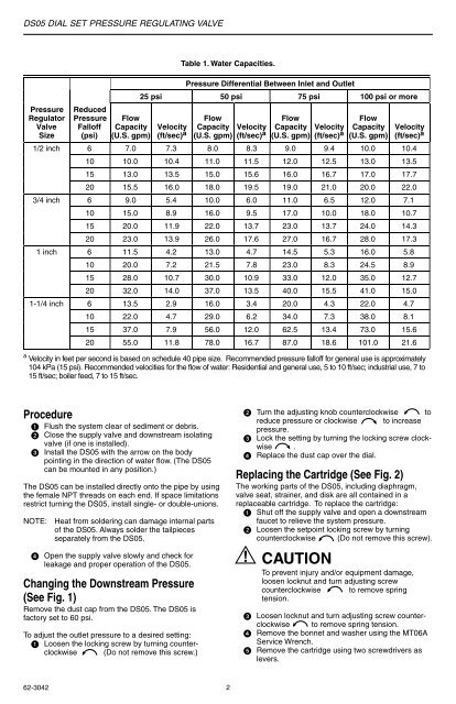
<strong>DS05</strong> DIAL SET PRESSURE REGULATING VALVE<strong>Pressure</strong>RegulatorValveSizeReduced<strong>Pressure</strong>Falloff(psi)FlowCapacity(U.S. gpm)Table 1. Water Capacities.<strong>Pressure</strong> Differential Between Inlet and Outlet25 psi 50 psi 75 psi 100 psi or moreFlowCapacity Velocity(U.S. gpm) (ft/sec) aFlowCapacity Velocity(U.S. gpm) (ft/sec) aFlowCapacity(U.S. gpm)VelocityVelocity(ft/sec) a(ft/sec) a1/2 inch 6 7.0 7.3 8.0 8.3 9.0 9.4 10.0 10.410 10.0 10.4 11.0 11.5 12.0 12.5 13.0 13.515 13.0 13.5 15.0 15.6 16.0 16.7 17.0 17.720 15.5 16.0 18.0 19.5 19.0 21.0 20.0 22.03/4 inch 6 9.0 5.4 10.0 6.0 11.0 6.5 12.0 7.110 15.0 8.9 16.0 9.5 17.0 10.0 18.0 10.715 20.0 11.9 22.0 13.7 23.0 13.7 24.0 14.320 23.0 13.9 26.0 17.6 27.0 16.7 28.0 17.31 inch 6 11.5 4.2 13.0 4.7 14.5 5.3 16.0 5.810 20.0 7.2 21.5 7.8 23.0 8.3 24.5 8.915 28.0 10.7 30.0 10.9 33.0 12.0 35.0 12.720 32.0 14.0 37.0 13.5 40.0 15.5 41.0 15.01-1/4 inch 6 13.5 2.9 16.0 3.4 20.0 4.3 22.0 4.710 22.0 4.7 29.0 6.2 34.0 7.3 38.0 8.115 37.0 7.9 56.0 12.0 62.5 13.4 73.0 15.620 55.0 11.8 78.0 16.7 87.0 18.6 101.0 21.6a Velocity in feet per second is based on schedule 40 pipe size. Recommended pressure falloff for general use is approximately104 kPa (15 psi). Recommended velocities for the flow of water: Residential and general use, 5 to 10 ft/sec; industrial use, 7 to15 ft/sec; boiler feed, 7 to 15 ft/sec.Procedure Flush the system clear of sediment or debris. Close the supply valve and downstream isolatingvalve (if one is installed). Install the <strong>DS05</strong> with the arrow on the bodypointing in the direction of water flow. (The <strong>DS05</strong>can be mounted in any position.)The <strong>DS05</strong> can be installed directly onto the pipe by usingthe female NPT threads on each end. If space limitationsrestrict turning the <strong>DS05</strong>, install single- or double-unions.NOTE:Heat from soldering can damage internal partsof the <strong>DS05</strong>. Always solder the tailpiecesseparately from the <strong>DS05</strong>. Open the supply valve slowly and check forleakage and proper operation of the <strong>DS05</strong>.Changing the Downstream <strong>Pressure</strong>(See Fig. 1)Remove the dust cap from the <strong>DS05</strong>. The <strong>DS05</strong> isfactory set to 60 psi.To adjust the outlet pressure to a desired setting: Loosen the locking screw by turning counterclockwise(Do not remove this screw.) Turn the adjusting knob counterclockwise toreduce pressure or clockwise to increasepressure. Lock the setting by turning the locking screw clockwise. Replace the dust cap over the dial.Replacing the Cartridge (See Fig. 2)The working parts of the <strong>DS05</strong>, including diaphragm,valve seat, strainer, and disk are all contained in areplaceable cartridge. To replace the cartridge: Shut off the supply valve and open a downstreamfaucet to relieve the system pressure. Loosen the setpoint locking screw by turningcounterclockwise (Do not remove this screw).CAUTIONTo prevent injury and/or equipment damage,loosen locknut and turn adjusting screwcounterclockwise to remove springtension. Loosen locknut and turn adjusting screw counterclockwiseto remove spring tension. Remove the bonnet and washer using the MT06AService Wrench. Remove the cartridge using two screwdrivers aslevers.62-3042 2