Promat Flamebraker.pdf - SIG Technical Insulation
Promat Flamebraker.pdf - SIG Technical Insulation
Promat Flamebraker.pdf - SIG Technical Insulation

Create successful ePaper yourself
Turn your PDF publications into a flip-book with our unique Google optimized e-Paper software.
PARTITIONS &EXTERNAL WALLS5
EXTERNAL WALLSThe Fire Protection Handbook5EXTERNAL WALLSFire Testing MethodsNon-loadbearing external walls should normally be tested orassessed in accordance with BS 476: Part 22: 1987 and arerequired to satisfy the failure criteria of integrity and insulationwhen exposed to fire from either side. In some instances therewill be additional criteria concerning the heat radiation from theunexposed face of the walls. For additional advice, pleaseconsult <strong>Promat</strong> <strong>Technical</strong> Services Department.Design ConsiderationsIn the case of external walls, the proximity of a building tothe relevant (facing) boundary determines the probabilityof it being a danger to other buildings on adjoining sitesor of it being at risk from a neighbouring building on fire.Building Regulations specify different fire resistance periods forexternal walls depending upon their distance from the relevantboundary. Where the walls are required to provide fireresistance only from the inside, loadbearing capacity andintegrity are required to be satisfied for the full period; whereasinsulation is required for only 15 minutes. This means thatsatisfactory constructions will be very different from thoserequired to maintain insulation for the full period and wherefire resistance is required from either side.The following points should be considered when determiningthe correct specification to ensure an external wall will providethe required fire performance. Further advice can be obtainedfrom <strong>Promat</strong> <strong>Technical</strong> Services Department.1. Distance from the Relevant BoundaryBuilding Regulations does sometimes relax therequirements for external walls which are one metre ormore from the relevant property boundary. In most casesthe wall only needs to be tested or assessed for itsperformance when exposed to fire from within the building.In addition, the maximum insulation period required is only15 minutes.2. External CladdingThe external cladding can significantly affect the overallfire performance of an external wall. For example, somecomposite external cladding panels with expanded plasticcores may perform much worse than a single skin steelsheet due to the low melting point of the core.3. Structural SteelAll structural steel within a fire protected external wallshould also be protected. This includes walls which mayonly require to be partially protected. If the steel frame ofa single storey building has not been designed inaccordance with the document, ‘Fire and steelconstruction: The behaviour of steel portal frames inboundary conditions, 1990’ (2 nd Edition) published by theSteel Construction Institute, the rafters of the roof may alsoneed protection as their collapse could lead to the collapseof the external wall.Generally, any steelwork located on the non-fire side ofa SUPALUX ® wall lining will be adequately fire protected.4. Single Storey BuildingsThe external walls of single storey buildings whichmay otherwise not require to be fire protected, maystill require to be protected if they are too close to therelevant boundary.5. Cavity BarriersBuilding Regulations specify where cavity barriersare required.6. Thermal <strong>Insulation</strong>U-values will depend upon the complete wall design.These U-values can be improved by the addition of moremineral wool. For additional information, please consult<strong>Promat</strong> <strong>Technical</strong> Services Department.7. Impact ResistanceSUPALUX ® is robust and reasonably impact resistant.Where there is risk of heavy impact however, and in mostcases below a height of 2m above floor level, it is advisableto introduce additional framing members as stiffening.Protection barriers or masonry walls up to 2m in heightare often advisable.8. Wind LoadingThe <strong>Promat</strong> systems offer good resistance to wind inducedinternal pressures. If there are predominant openings in theexternal envelope of the building however, the advice of<strong>Promat</strong> <strong>Technical</strong> Services Department should be sought.NOTE: Scottish Regulations may require different periods of fire insulation.THE PASSIVE FIRE PROTECTION HANDBOOKPROMAT UK LIMITED94
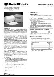
EXTERNAL WALLSThe Fire Protection HandbookWITHIN 1M FROM THE RELEVANT BOUNDARYTECHNICAL DATA30, 60 or 120 minutes fire rating, integrity and insulation in2➛8➛accordance with the criteria of BS 476: Part 22: 1987 firefrom either side.51. Horizontal sheeting rail at maximum 2.2m centres.2. External cladding, single skin of steel, aluminium or fibre8➛cement.➛3. SUPALUX ® 9mm thick, screw fixed to 38mm x 38mm x1 ➛0.8mm steel tees cut around and secured to the horizontalsheeting rail.3 ➛4 SUPALUX ® 9mm thick x 600mm wide, retained by springwedges inserted in to prepunched holes in the stems➛7of the FLAMEBRAKER ® GRID.5. SUPALUX ® cover fillet, 9mm thick x depth of sheeting rail.510 ➛➛6➛➛94Cover fillet to be positioned on both sides of sheeting rail.6. Vertical main tees at 603mm centres(FLAMEBRAKER ® GRID).7. Horizontal cross tees at every panel joint(FLAMEBRAKER ® GRID).8. Purlin strap (FLAMEBRAKER ® GRID).9. Galvanised perimeter angle, 25mm x 25mm x 0.6mm.Installation Method – Exposed grid.10. 30 minutes fire rating:Mineral wool not required.60 minutes fire rating:Mineral wool, 80mm x 23 kg/m 3 , should be suspendedin cavity by fixing to the underside of sheeting rails andextending down past lower rails behind internal lining andfixed between the sheeting rails using galvanised angle,50mm x 25mm x 0.6mm or similar, fixed through the angleand mineral wool to the rail at maximum 500mm centres.120 minutes fire rating:As for 60 minutes but with wired mineral wool quilt,50mm thick x 110 kg/m 3 .THE PASSIVE FIRE PROTECTION HANDBOOKPROMAT UK LIMITED96
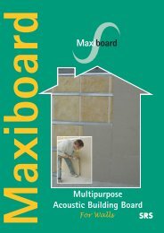
ROOF LININGSThe Fire Protection HandbookFire stop roof profilewith mineral woolROOF LININGSJunction of Compartment Wall with RoofWhere a compartment wall meets a roof, the roof may requireprotection over a distance of 1.5m from each face of the wall.If the roof does not have a continuous fire-protective lining, thenecessary protection can be provided with a board lining inFLAMEBRAKER ® GRID; details of the return up to the roofcovering are described below and shown in the illustrations.4Fire stop roof profilewith mineral wool1.5m minimumCompartment wallPurlins parallel to wall – (boards and mineral wool omitted forclarity).Purlins Parallel to the WallThe FLAMEBRAKER ® GRID is cut and turned through 90º andfitted next to the purlin by means of a strap and angle bracketas shown in the drawing. Boards are fixed parallel to thepurlins and held in place vertically in the grid by means ofspring wedges and supported horizontally on angles (notshown in the drawing) fixed to and spanning between the maintees of the grid. Boards are laid horizontally in the grid in thenormal fashion beneath the purlins with the mineral woolinsulation being laid on top of the boards, and used to linethe vertical boards. Roof profile should be fire stopped withmineral wool.Purlins at Right Angles to the WallBoards are fixed horizontally below the purlin with theinsulation laid on top as shown. Vertical boards are cut to fitwithin the purlin and fitted flush with the underside of the roofdeck and lined with mineral wool. Any gaps in the purlin are firestopped with mineral wool. Boards are fixed at the base to anangle fixed to the main tee of the grid and also fixed to anotherangle spanning between, and fixed to, the purlins.1.5m minimumCompartment wallPurlins at right angle to wallTHE PASSIVE FIRE PROTECTION HANDBOOKPROMAT UK LIMITED74
ROOF LININGSThe Fire Protection HandbookSTEEL SHEET ROOFINGFire resistances quoted are derived from independent assessments based on BS 476: Part 8, and refer to fire exposure from inside.Fire Resistance (minutes)Stability& integrity <strong>Insulation</strong> Specification Detail30 30 Lining: 6mm Masterboard, maximum size1200mm x 600mm.Infill: mineral wool 80mm thick (23kg/m 3 ).60 30 Lining: 6mm Supalux, maximum size1800mm x 600mm.Infill: mineral wool 80mm thick (23kg/m 3 ).120 30 Lining: 6mm Supalux, maximum size1800mm x 600mm.Infill: mineral wool 75mm thick (33kg/m 3 ).4Note: These specifications do not cover the use of composite cladding systems with combustible cores.PROMAT UK LIMITEDTHE PASSIVE FIRE PROTECTION HANDBOOK75
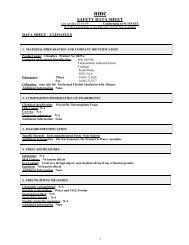
ROOF LININGSThe Fire Protection HandbookFLAMEBRAKER ® GRID COMPONENTSAll hot dip galvanised steel to BS 2989: 1982, minimum galvanic coat G200.Main tees35mm x 35mm x 3600mm long,punched at 150mm centres for crosstees and spring wedges. Main tees havesplice tabs at both ends to forminterlocking joints.Cross tees35mm x 35mm x 603mm effectivelength, punched to hold spring wedges.4Fixing straps18mm wide x 300mm or 450mm long,split and notched at one end to allowsnapping on to main tee stalk. No drillingor screwing is required.Spring wedges11mm x 17mm x 60mm long,corrugated to prevent slipping. Suitablefor both 6mm and 9mm thick boards.Angle trims90º, 120º or 135º angles are available ingalvanised steel (size 25 x 25 x 3600mmlong).<strong>Insulation</strong>retaining clipsUsed to retain insulation in vertical orsteply sloping installations, 15mm wide x140mm long with 80mm split ends.Clipped on to main tees, ends simplybend out to retain the insulation.Spring wedgeMain teeFixing strapSquare punched hole for crosstee, spring wedge or insulationretaining clipsInterlockingsplice tabsMain teeCross teeExpansioncut out<strong>Insulation</strong>retaining clipsFLAMEBRAKER ® Components DetailTHE PASSIVE FIRE PROTECTION HANDBOOKPROMAT UK LIMITED76