
Create successful ePaper yourself
Turn your PDF publications into a flip-book with our unique Google optimized e-Paper software.
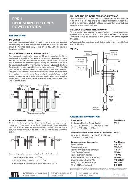
FPS-IREDUNDANT FIELDBUSPOWER SYSTEMINSTALLATIONMOUNTINGMTL-Relcom Redundant Fieldbus Power Systems (FPS) are designedfor mounting on 35mm DIN rail. For maximum cooling, the DIN railshould be mounted horizontally so that air can flow vertically betweenthe <strong>power</strong> modules.INPUT POWER SUPPLY CONNECTIONSFor redundant operation, two separate DC <strong>power</strong> supplies should beconnected to each FPS. Four pairs of terminals are provided on eachFPS for this purpose; two pairs for each input <strong>power</strong> supply. The extrapair of terminals for each input <strong>power</strong> supply are intended to be usedfor connection to another FPS installed immediately adjacent to the first.Prefabricated jumper assemblies are included with each FPS-I for thispurpose. When multiple Fieldbus Power Systems are wired togetherusing jumper assemblies, redundant connections should be made to thetwo input <strong>power</strong> supplies using the terminal pairs located at each end ofthe row of systems. Up to eight segments can be wired together usingthe supplied jumper assemblies An example of three systems wired thisway is shown below:H1 HOST AND FIELDBUS TRUNK CONNECTIONSTwo 3-conductor (+, shield, and -- ) connectors are provided forconnection to the H1 host and to the fieldbus trunk cable. A green LEDnext to the connector labeled ‘Fieldbus’ indicates that <strong>power</strong> is beingsupplied to the fieldbus segment.FIELDBUS SEGMENT TERMINATORSTwo terminators are required for each Fieldbus H1 network segment.One terminator is built into the RCT backplane of each FPS. The secondTerminator should be positioned at the opposite end of the segmenttrunk cable.A Redundant Coupler without a built-in terminator is also available (partnumber FPS-RC).WIRING18-30 VDCPower Supply A18-30 VDCPower Supply BSystemAlarm-+-+A2A1-+-+212019181716- S+22 23 24-S+FieldbusH1 Host456789A2A1-+-+Host System ConnectionsIntermodule JumperRCT RCT RCTAlarm24V A24V BIPM IPM IPM IPM IPM IPM24V A24V B15 14 13+ S -FPS-RCorFPS-RCTFieldbusTrunk Cable+ S -Fieldbus Segment ConnectionsORDERING INFORMATIONALARM WIRING CONNECTIONSNext to the input <strong>power</strong> terminals, terminal pairs are provided forconnection of the alarm circuit. Each prefabricated jumper assemblyincludes a pair of wires for the alarm circuit. To complete the alarmcircuit, a jumper wire must be installed on the end module as shownbelow:AlarmSenseRCT RCT RCTLast ModuleJumperIn normal operation, the alarm circuit is closed. It will open if:• either input <strong>power</strong> supply < 18V dc• output of either <strong>power</strong> module < 22V dc• the fieldbus is shorted (short circuit resistance