
You also want an ePaper? Increase the reach of your titles
YUMPU automatically turns print PDFs into web optimized ePapers that Google loves.
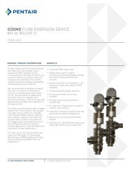
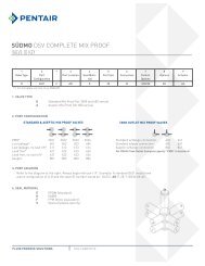
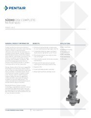
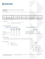
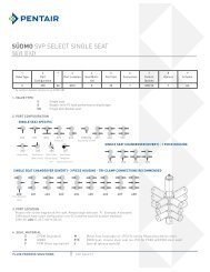
SÜDMODSV COMPLETEdouble seat valvesFOOD & BEVERAGEdsv complete Double seat valves
Upper shaft passageSupport ringEnsures better guidance and optimisedfriction behaviourProfile sealMinimised contact areas to ensure long lifeand improved wear and friction behaviour;special design prevents press-out (pressurepulses) or pull-out (sticky media).O-ringSeal between valve housing and housingholderSeat area (on TYPE D 620)Double O-ring sealIn the upper valve disc, the upper O-ringensures a product seal in closed valveposition, and lower O-ring ensures aleakage chamber seal in open valve positionRSC radial sealSpecial shape ensures improvedperformance and doubling of swellcompensation compared with conventionalradial O-ring seals. Smaller contact areaensures longer lifeLOWER shaft passageProfile sealMinimised contact areas to ensure long lifeand improved wear and friction behaviour;special design prevents press-out (pressurepulses) or pull-out (sticky media).Support ringEnsures improved guidance and optimumfriction behaviourO-ringSeal between valve housing and housingcoverDSV COMPLETE double seat valves5
asic valve functionsBasic valve positionsValve closed• Media are separated, secure against mixing• Any leaks escape to the environment without pressureValve open• Lower valve disc lifts and closes the leakage chamber• Product in the leakage chamber is discharged to the outsideValve closedValve openValve cleaning - Cyclic functionsCleaning via lower valve seat• Lower valve disc is raised while cleaning the lower line (cyclic lift via predefined ring gap)• Lower valve seat, disc seal, leakage chamber and leakage drain are cleanedCleaning via upper valve seat• Upper valve disc is raised while cleaning the upper line(cyclic lift via predefined ring gap)• Upper valve seat, disc seal, leakage chamber and leakage drain are cleanedCleaning via lowervalve seatCleaning via uppervalve seatextended valve functionsLEAKAGE cleaning via externalflushing connectionSterilisation / FLUSHING upperand lower shaft areaShaft flushing oflower valve discCleaning of leakagechamber byexternal flushingconnectionValve sterilisationCleaning of leakage chamber via externalflushing connection• Leakage chamber and leakage drain arecleaned via an external connectionSterilisation or flushing via externalconnections• Sterilisation or flushing of lower andupper shaft areaFlushing of lower shaft area(Scallop design)• Flushing of shaft area during activation ofcyclic lift of lower valve plate6
DESIGN D 620• Product loss free switching(leakage free)• Cycling of valve disc during cleaningallows cleaning of leakage chamber• Lower valve disc radial sealRSC (Radial Seal Complete)1. Valve closed2. Valve open3. Cycling lower seat4. Cycling upper seat1. 2.3. 4.DESIGN D 630• Product loss free switching(leakage free)• No cyclic lift function• Cleaning via external flushing connection• Lower valve disc radial sealRSC (Radial Seal Complete)1. Valve closed2. Valve open3. Cleaning via flushingconnection1.3.2.DSV COMPLETE double seat valves9
DESIGN D 620 S-sp (suitable for sterilising – flushing)• Product loss free switching (leakage free)• Cycling of valve disc during cleaning allows cleaning ofleakage chamber• Flushing chamber for flushing/sterilisation of shaft areas• Cleaning/sterilisation via external flushing connection (Sp)• Lower valve disc radial sealRSC (Radial Seal Complete)1. Valve closed2. Valve open3. Cyclic lift of lower valve disc4. Cyclic lift of upper valve disc5. Sterilisation/flushing1. 2.5.3. 4.DESIGN D 620 U (change over valve)• Product loss free switching(leakage-free)• Cyclic lift functions for cleaning ofleakage chamber• Switchover function• Lower valve disc radial sealRSC (Radial Seal Complete)1. Valve closed2. Valve open3. Cyclic lift of lower valve disc4. Cyclic lift of upper valve disc1. 2.3. 4.10
Design D 640 (bottom seat valve / tank outlet valve)• Product loss free switching(leakage free)• Cyclic lift functions for cleaning ofleakage chamber• Lower valve disc radial sealRSC (Radial Seal Complete)1. Valve closed2. Valve open3. Cyclic lift of lower valve disc4. Cyclic lift of upper valve disc1. 2.3. 4.DESIGN D 650 (for ring pipes)• Product loss free switching(leakage free)• Cyclic lift functions for cleaning ofleakage chamber• Lower valve disc radial sealRSC (Radial Seal Complete)1. Valve closed2. Valve open3. Cyclic lift of lower valve disc4. Cyclic lift of upper valve disc1. 2.3. 4.DSV COMPLETE double seat valves11
design D 660 (for CIP-areas)• Low product loss switching (low leakage)• Flushing of the leakage chamber during cyclic lift (opening/closing)• Lower valve disc conical seal (O-ring)• Vertical mounting position (other mounting positions on request)• Only with EPDM sealing available (standard)1. Valve closed2. Valve open3. Cyclic lift opening/closingof the valve-> short-time flushing effectof the leakage chamber/exit1.2. 3.DESIGN D 365it PMOVARIANTS• Product loss free switching (leakage free)• Cyclic lift functions for cleaning of leakage chamber• Lower valve disc radial seal RSC (Radial Seal Complete)• Shaft flushing (for maximum security)• Three-seat valve (deflector)• Meets aligned requirements of PMO and 3A 85-021. Valve closed2. Valve open3. Cyclic lift of lower valve disc4. Cyclic lift of upper valve discD 365it toBottom Seat Valve / Tank Outlet ValveSpecial design for direct integration intothe tank. The design with no dead zonesallows optimum tank cleaning.Type D 640 Type D 6501. 2.3. 4.D 365itCheese curd designThe large open cross section of the 365itComplete Cheese Curd Outlet PMO Mix ProofValve provides gentle handling of the curd,and allows particles of up to approximately 1.5inches to pass unobstructed through the valve.12
General technical dataMaterialArea in contact with product1.4404 (AISI 316L)Area not in contact with product1.4301 (AISI 304) / 1.4307 (AISI 304 L)OptionalHigher quality materialsSeals*EPDM / HNBR / FKM*All seal qualities are FDA-compatibleOperating temperaturesPressuresControl air pressureStandard 6 bar (87 psi) – 8 bar (116 psi)Operating pressureStandard 10 bar (145 psi)*Lower operating pressures apply to thefollowing types:D640 5 bar (72.5 psi)D650 5 bar (72.5 psi)D660 5 bar (72.5 psi)*Depending on type and nominal widthSURFACESProduct wettedRa ≤ 0,8 μmOthersRa ≤ 1,6 μmOptionalHigher-quality surfaces, e-polishedCONNECTIONSPipe dimensions in accordance with- DIN 11850-2 (DIN 11866-A)- ASTM A270 (DIN 11866-C) (ASME BPE-2009)- DIN EN ISO 1127 (DIN 11866-B)EPDMStandardHNBRoptionalFKMoptionalHot water+95 °C (203 °F) continuousSteam+130 °C (266° F) continuous+150 °C (300° F) brief sterilisation(15-20 minutes)Cold water+1 to +2 °C (33.8 – 35.6°F) continuousHot water+95 °C (203 °F) continuousSteam+121 °C (250° F) continuous+140 °C (284 °F) brief sterilisation (15-20minutes)Cold water+1 to +2 °C (33.8 – 35.6°F) continuousHot water+80 °C (176 °F) continuousSteam+121 °C (250° F) brief sterilisation (15-20minutes)Cold water+1 to +2 °C (33.8 – 35.6°F) continuousConnection layoutConnection markingsd 621 d 622 d 623 d 624HEIaFKGCJBDLDifferent customer needs can be metthanks to the housing constructed of solidmaterial. Discuss your needs with us at anytime.Optional accessoriesAir pressure amplifier / booster• Supports main lift function• Used for low control air pressure**Control air pressure depending on type &nominal widthPosition feedback OPEN/CLOSED• Proximity initiator M12Position feedback upper valve disc• Feedback CLOSED• Proximity initiator M8DSV COMPLETE double seat valves13
IDEAL FOR VALVE manifoldsDSV COMPLETEPentair Südmo valve manifolds- Our Know-How, your successPLANNING, DESIGN & PRODUCTIONCUSTOMER BENEFITSA successful process begins with thedesign and assembly of the valves intolarger function units. As well as the purefunctionality of the system, many otherpoints must be taken into account:• Selection of suitable components• Correct installation position of allindividual components• Arrangement with no dead zones• No sumps or domes• Complete drainability• Arrangement compatible with orbitalwelding• Reduction in number of weld seams• Compensation for heat expansion• Adequate support and stabilisation ofcomponents• Capture and discharge of leakage• Simple maintenance work3D drawing of a valve manifoldBefore production comes planning. Usingmodern 3D systems, the valve manifoldis planned in every detail and the resultpresented to the customer. Then productionof the valve manifold can begin.Building the frameA stainless steel tube frame holds the valvemanifold. Each frame is made individuallyto meet the customer's needs.Mounting the valvesThe individual parts of the valves formounting come together on the workbench.The valve housing is sent directly to theplant construction.Housing preparationBefore combining the valve housings into amanifold, the housings are equipped withflanges, elbows and other componentsusing welding machines.Orbital weldingThe valve housing is welded using orbitalwelders. Together with accurate weld seampreparation, this ensures reproducible weldseams of the highest quality.PreparationAll weld seams of the valve manifold areexternally prepared mechanically. The valvemanifold is then cleaned.Fitting valve upper partsFinally, the valve manifold is fitted with thevalve upper parts, the air hoses suitableto the customer's needs, and the electricwiring for the process control heads isprepared; the finished valve manifold isthen subjected to a final test.Finished valve manifoldsThe finished valve manifolds can beinstalled in your plant directly afterdelivery and brought into operation.• Cost-efficient complete package• Decades of experience in design andproduction• Compact construction• Simple and rapid installation• Perfect integration in process control(e.g. IntelliTop2.0 with 24VDC, ASinterface, DeviceNet, or 110VAC)• Countless possible variations inconsultation with our experts• Simple access for maintenance(e.g. with access platforms or steps)• Excellent WIG weld seam qualities toDIN EN 287• Valve manifold production observingPressure Vessel Directive 97/23/EC14
Intelligent Control TechnologyINTELLITOP ® 2.0The innovative controlunit offers the customercountless possibilitiesfor automation ofprocess systems, andhence considerablepotential for increasingefficiency.The IntelliTop 2.0 was awarded the IFProduct Design Award 2010 for its perfectcombination of function and aesthetics.The IntelliTop 2.0 control unit from PentairSüdmo combines control and monitoringof process valves in one unit. The decentralarrangement of the control heads on theprocess valves allows a reduction in hoseand cable lengths and leads to a clearsystem structure.The heart of the IntelliTop 2.0 is the travelmeasurement system to detect up to threeswitch positions of the process valve. Greatemphasis has been placed on simpleprogramming by means of three Teach-Inkeys. This guarantees rapid and processreliablecommissioning. At the same time,the closed travel measurement systemserves as a protective tube which preventsrisk of injury when the control head is open,and protects the internal technology oninstallation of the head.BENEFITSCommunication24 V DCAS interfaceDeviceNet110 V ACTravel Measurement SystemLift range 85 mmFeedback 3 positions, adjustable,connection for externalsignalMagnetic valvesNumberFlowChoke function0-3 pcs200 l/minIntake and extraction airseparateElectrical connections24 VDC Cable passageAS interface Cable with 4-pin M12x1plugDeviceNet Cable with 5-pin M12x1plug110 V AC Cable passagePneumatic connectionsPush-fit hose connection Ø 6 mm(optional 5/16“)Push-fit hose connection Ø 8 mm (1/4“)Other dataLED status display green, yellow, redProtection classes IP65 and IP 67 combinedIP 69KEx-zone Zone 2/22Technical Data BENEFITS• Process-reliable system monitoring,simple, intuitive and rapidimplementation• Process valve switch times can be setusing integral supply and extraction airchokes• All-round LED display for visual statusmonitoring (colour allocation can beconfigured)• Simplified valve maintenance thanksto maintenance function which can beactivated externally• Plant-specific adaptations via integratedmicrocontroller• Integrated microcontroller suppliesadditional information• Short air hose and cable routes, clearstructure of process plant• Simple, rapid fault analysis and repair, soreduction in plant downtimes• Compact construction and optimumcompatibility with Pentair Südmo processvalves• Scanning of all valve positions possible indouble-seat valveDSV COMPLETE double seat valves15
SÜDMO componenTS GMBHIndustriestrasse 7, 73469 Riesbürg, Germany WWW.Suedmo.deAll Pentair trademarks and logos are owned by Pentair, Inc. All other brand or product names are trademarks or registered marks of their respective owners. Because we are continuously improving our products and services, Pentair reserves the right to change specifications without prior notice.Pentair is an equal opportunity employer.DSV Brochure E-1/12 © 2012 Pentair, Inc. All Rights Reserved.