
Create successful ePaper yourself
Turn your PDF publications into a flip-book with our unique Google optimized e-Paper software.
1. This product may be used for model airplane or surface use if on the correct frequency.The product described in this manual is subject to regulations of the Ministry ofRadio/Telecommunications and is restricted under Japanese law to such purposes.2. Exportation precautions(a) When this product is exported from Japan, its use is to be approved by the Radio Law ofthe country of destination.(b) Use of this product with other than models may be restricted by Export and TradeControl Regulations. An application for export approval must be submitted.3. Modification, adjustment, and replacement of partsFutaba is not responsible for unauthorized modification, adjustment, and replacement ofparts of this product.This device complies with part 15 of the FCC rules. Operation is subject to the followingtwo conditions:(1) This device may not cause harmful interference, and(2) This device must accept any interference received, including interference that may causeundesired operation.The RBRC TM SEAL on the (easily removable) nickel-cadmium battery contained in Futabaproducts indicates that Futaba Corporation of America is voluntarily participating in anindustry program to collect and recycle these batteries at the end of their useful lives, whentaken out of service within the United States. The RBRC TM program provides a convenientalternative to placing used nickel-cadmium batteries into the trash or municipal waste whichis illegal in some areas.Futaba Corporation of America's payments to RBRC TM makes it easy for you to return thespent battery to Futaba for recycling purposes. You may also contact your local recyclingcenter for information on where to return the spent battery. Please call 1-800-8-BATTERYfor information on Ni-Cd battery recycling in your area. Futaba Corporation of America'sinvolvement in this program is part of its commitment to protecting our environment andconserving natural resources.NOTE: Our instruction manuals need to encourage our customers to returnspent batteries to Futaba or a local recycling center in order to keep a healthyenvironment.RBRC TM is a trademark of the Rechargeable Battery Recycling Corporation.Pay special attention to the safety at the parts of this manual that are indicated by thefollowing marks.:Procedures which may lead to a dangerous condition and cause death orserious injury to the user if not carried out properly.:Procedures which may lead to a dangerous condition or cause death orserious injury to the user if not carried out properly, or procedures where the probability ofsuperficial injury or physical damage is high.:Procedures where the possibility of serious injury to the user is small, butthere is a danger of injury, or physical damage, if not carried out properly.Symbol: ; Prohibited ; Mandatory
INSTRUCTION MANUAL6XAs / 6XHsFOR AIRCRAFT / HELICOPTERSFM/PCM SYSTEM, 6 CHANNELSFutaba Corporation
INTRODUCTIONThank you for purchasing a Futaba ® 6XAs/6XHs series digital proportional R/C system.This system is extremely versatile and may be used by both beginners and experts. In order foryou to make the best use of your system and to fly safely, please read this manual carefully. Ifyou have any difficulties while using your system, please consult the manual, your hobby dealer,or Futaba. This product is to be used for sport and recreational flying of radio-control modelsonly. Futaba is not responsible for the results of use of this product by the customer or for anyalteration of this product, including modification or incorporation into other devices by thirdparties. Modification will void any warranty and is done at owner’s risk..Your T6XAs or T6XHs system includes the following components:• T6XAs/T6XHs Transmitter. May be programmed for planes or helicopters, both withspecial mixing function, 6 model memories. (Transmitting frequency: 29, 35, 36, 40, 41, 50,60 or 72 Mhz band)• R127DF or R116FB Receiver (FM system). R138DP or R148DP Receiver (PCM system).(Receiving frequency: 29, 35, 36, 40, 41, 50, 60 or 72 Mhz band)• Servos, S3003 with mounting hardware and servo arm assortment (or S148 Servo)• Receiver battery (or Battery Box)• Switch harness with charging jack• Aileron extension cord (use to easily connect to an aileron servo in a detachable wing)• AC battery charger• Owner’s <strong>Manual</strong>Owner’s <strong>Manual</strong>This manual is not just a translation — it has been carefully written from scratch to be ashelpful to you, the new owner, as possible. There are many pages of setup procedures,examples, explanations, and trimming instructions. If you feel that any corrections orclarifications should be made, please jot them down on a piece of paper and send them to thefactory. The information contained in this manual is subject to change without notice due topossible changes in manufacturing procedures or updates.“Futaba” is a registered trademark of the Futaba Corporation of America.<strong>Manual</strong> text copyright ©1996 by Don Edberg, Dynamic Modelling Co. All rights reserved– ii –
TABLE OF CONTENTSIntroduction to the T6XAs/T6XHs System .........................................................................1ACRO Transmitter Controls and Switch Identification ......................................................2ACRO & HELI Transmitter Switch Functions ...................................................................2Charging the Ni-Cd Battery.................................................................................................3Operating With The Trainer Cord .......................................................................................3Adjusting Stick Length & Tension......................................................................................4Changing Transmitter Mode................................................................................................5Reversing The Throttle Stick...............................................................................................5ACRO Receiver and Servo Connections.............................................................................6Radio Installation Precautions.............................................................................................7Airplane Frequencies (U.S.A.) ............................................................................................9Transmitter Displays and Programming Keys...................................................................10Warning Displays ..............................................................................................................11Safety Precautions (DO NOT operate without reading)....................................................12AIRCRAFT FUNCTIONS INDEX (ACRO Menu) 13Aircraft (ACRO) Functions Diagram ................................................................................14Aircraft Setup Example (Pattern model) ...........................................................................15Pattern Aircraft Trimming Chart .......................................................................................22ATV................Adjustable Travel Volume.........................................................................24D/R ................Dual Rates..................................................................................................25EXP ...............Exponential Settings ..................................................................................26REV ...............Servo Reverse ............................................................................................27STRM............Subtrim ......................................................................................................27FLPR .............Flaperon (combined flaps & ailerons) .......................................................28FLTR .............Flap trim.....................................................................................................29ABRK ............Airbrake settings........................................................................................30VTAL .............V-tail mixing..............................................................................................31ELVN.............Elevon mixing (tailless models) ................................................................321->4 ...............Rudder Coupling........................................................................................336->2 ...............Flap -> Elevator mixing.............................................................................342->6 ...............Elevator -> Flap mixing.............................................................................35PMX1, 2........Programmable Mixer #1, #2......................................................................35F/S .................Failsafe function (only in PCM mode) ......................................................37PARA ............Parameter menu .........................................................................................38REST.............Data Reset..................................................................................................38– iii –
DRSW........... Dual Rate Switch Select............................................................................ 39ACRO ........... Acrobatic model mode .............................................................................. 39HELI.............. Helicopter model mode............................................................................. 39MOD ............. Modulation (FM/PPM or PCM)................................................................ 40COPY ........... Data Copy ................................................................................................. 40TMEM........... Trim Memory............................................................................................ 41MODL ........... Model select .............................................................................................. 42HELICOPTER SECTION INDEX 43Helicopter (HELI) Functions Index .................................................................................. 43Helicopter Function Menu Diagram ................................................................................. 43Helicopter Transmitter Controls and Switch Identification.............................................. 44Helicopter Setup Instructions............................................................................................ 45Helicopter Trimming Chart............................................................................................... 48PI-N, I, H ...... Pitch Rate (Normal, Idle-Up, Hovering)................................................... 49HV-T ............. Hovering Throttle...................................................................................... 49IDLE.............. Idle-Up function........................................................................................ 50HOLD............ Throttle Hold............................................................................................. 51REVO ........... Revolution mixing..................................................................................... 51R-OF............. Rudder Offset............................................................................................ 52HV-P ............. Hovering Pitch .......................................................................................... 53SWSH........... Swashplate Type & AFR .......................................................................... 53Glossary............................................................................................................................ 55Data Recording Sheets: ACRO, HELI.......................................................................... 56Factory Repair Service ................................................................................................... 57– iv –
Introduction to the 6XAs/6XHs SystemsTRANSMITTERThe versatile T6XAs/T6XHsPCM1024 multi-function 6-channeltransmitter may be used with any FutabaFM/PPM receiver! In addition, your systemwill work with Futaba PCM1024 receiverswhen you select the built-in PCMtransmission option. The liquid-crystaldisplay panel allows rapid data input into itseasy-to-read LCD display.The T6XAs/T6XHs system comescomplete with programming for ACRO(aircraft) and HELI (helicopter) mixing andcan accommodate virtually any modelconfiguration. The compact, ergonomicallydesignedtransmitter holds completelyindependent memories for six differentmodels.The T6XAs/T6XHs features a newstick design which provides an improvedfeel. The sticks’ length and tension may beadjusted. Switches are provided for dualrate (D/R), programmable mixers (PMX),and other functions. For those learning tofly, the transmitter has “buddy-box”capability where a second transmitter maybe used by an experienced pilot as aninstructor. [The trainer cord is soldseparately.]Standard programming featuresinclude servo reversing for all channels,ATV on all channels, dual rates,exponential, and fail safe on all channels(PCM transmission only). In addition, theT6XAs/T6XHs features a number of handymixing features applicable to all types offlying models. For aircraft, the extensivepreprogrammed mixing features include:flaperon, V-tail, elevon, airbrake, elevator ->flap, and flap -> elevator. Helicopterfeatures include hovering pitch and throttle,revolution mixing, swashplate typeselection, and rudder offset. [Note: theT6XAs/T6XHs may be used for sailplanes.For these we recommend Futaba’s System 8,which contains extensive sailplaneprogramming.]Transmitter Specifications:Operating system: 2-stick, 6 channels,PCM1024 systemModulation: FM/PPM or PCM, switchablePower supply: 9.6V Ni-Cd batteryCurrent drain: 250mARECEIVERThe R127DF seven-channel receiverincluded with your system is a compacthigh-sensitivity narrow-band unit, providingsuperior range and performance.Receiver Specifications (FP-R127DF)Type: FM, Dual conversionIntermediate frequencies: 455kHz, 10.7MHzPower requirement: 4.8V or 6V Ni-Cd batteryCurrent drain: 14mA @ 4.8VSize: 1.39x2.52x0.82” (35.3x64.0x20.8mm)Weight: 1.5oz (42.5g)Receiver Battery4-cell NR-4J (NR-4RB for heli version)Capacity: 500mAH (1,000mAH for NR-4RB)Weight: 3.3oz/94g (3.9oz/111g for NR-4RB)SERVO SPECIFICATIONSServo type: S3003 (Standard)Control system: Pulse width control, 1.52msneutralPower requirement: 4.8V (from receiver)Output torque: 44.4oz-in (3.2kg-cm)Operating speed: 0.23sec/60°Size: 1.59x0.78x1.41” (40.4x19.8x36mm)Weight: 1.3oz (37.2g)*Specifications and ratings are subject to change without notice.– 1 –
– 2 –
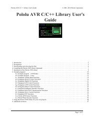
TRANSMITTER CONTROLS – AIRCRAFT (T6XAs System)Flap Knob (Ch. 6)Airbrake Switch (B)Elevator DualRate Switch (A)Landing GearSwitch (Ch. 5,Sw. E)Trainer PushbuttonSwitchON indicatorlightRudder / ThrottleStickThrottle TrimRudder TrimCarrying Liquid-CrystalHandle DisplayAntennaAileron DualRate Switch (C)Elev -> FlapMixing Switch(D)Neckstrap HookElevator Trim LeverAileron / ElevatorStickAileron Trim LeverProgramming KeysCrystal CoverCOMPUTER RADIOFun to FlyCharging JackPCM/PPM SELECTABLEOn-Off SwitchThis figure shows the default assignments for a Mode 2 aircraft system as supplied by the factory.SWITCH ASSIGNMENT TABLEThe functions activated by the switches and knobs for a Mode 2 transmitter are shown in thetable below. Note that some of the functions will not operate until activated in the mixingmenus. For a Mode 1 transmitter, elevator and throttle are reversed, as are switches D and E.Switch / Knob ACRO HELISwitch A Up = Elevator Dual Rate 1;Down = PMX1 & PMX2 on; Elev D/R 2Up = Elevator Dual Rate 1;Down = Elev D/R 2Switch B Down = Airbrake on Gyro sensitivity (if desired)Switch C Up = Aileron Dual Rate 1Down = Aileron Dual Rate 2Up = Aileron Dual Rate 1Down = Aileron Dual Rate 2Switch D Forward = 2 -> 6 (Elev -> Flap) on Forward = Throttle Hold on, andREVO offSwitch E Landing Gear Forward = Idle-up on, Rudderoffset on, and REVO offSwitch F TrainerTrainer(Push-button)CH6 knob Flap or Flap trim if flaperon function(FLPR) onHovering Pitch– 3 –
CHARGING THE Ni-Cd BATTERIES1. Connect the transmitter charging cord into the charging socket (on the right of the case,when facing the front) and airborne Ni-Cd batteries to the receiver connector on thecharger.2. Plug the charger into a wall socket.3. The charger’s LEDs should light, indicating charging current is flowing. The batteriesshould be left on charge for about 15 hours.Only charge the batteries with the charger supplied withyour system. The use of a fast charger may damage the batteries by overheating anddramatically reduce their lifetime.You should fully discharge your system’s batteriesperiodically to prevent a condition called “memory.” For example,if you only make two flights each session, or you regularly use only a small amount of thebatteries’ capacity, the memory effect can reduce the actual capacity even if the battery isfully charged. You can cycle your batteries with a commercial cycling unit, or by leaving thesystem on and exercising the servos by moving the transmitter sticks. Cycling should bedone every one to two months, even during the winter or periods of long storage. Keep trackof the batteries’ capacity during cycling; if there is a noticeable change, you may need toreplace the batteries.NOTE: If you need to remove or replace the transmitter battery, do not pull on its wires toremove it. Instead, gently pull on the connector’s plastic housing where it plugs in to thetransmitter.Operating With The Trainer CordAn optional training cord is available from your dealer. The cord may be used to helpa beginning pilot learn to fly easily by allowing a second transmitter, operated by anexperienced instructor, to be connected to this system. The instructor may override thebeginning pilot at any time to bring the model back under safe control. For training, theT6XAs/ T6XHs transmitter may be connected to another T6XAs/XHs system, as well as toany 4VF, 6VA Skysport, 6XA, Super 7, System 8, or 9Z series transmitter.To use the trainer cord:1. Set up both the student’s and instructor’s transmitters to have identical trim and controlmotions. If the instructor’s transmitter is on a different frequency than the student’s, usethe student’s as the master transmitter and the other as the student’s.– 4 –
2. Set the student transmitter modulation mode to PPM. Collapse the student’s antenna, andfully extend the instructor’s antenna. Remove the RF module from the transmitter heldby the student (if it is a module-type transmitter).3. Plug one end of the trainer cord into eachtransmitter, with power switched off. The trainerjack is in the center of the rear face of thetransmitter. Do not force, the connector is keyed.4. Turn on the instructor’s transmitter. DO NOT turnon the student transmitter power. Move the controlson the instructor’s transmitter, and verify eachcontrol moves the proper direction. Now verify thatthe student’s trims and control travels match the instructor’s by using the trainer buttonand switching back and forth while leaving the control sticks and trims alone, thenmoving the control sticks.5. The instructor’s transmitter has normal control over the model unless the trainer button ispushed, when the student’s has control. If control is lost, the instructor should release thetrainer button and resume controlling the model.OTHER T6XAS/XHS ADJUSTMENTSAdjustable length non-slip control sticksYou may change the length of thecontrol sticks to make your transmitter morecomfortable to hold and operate. To lengthenor shorten your transmitter’s sticks, first unlockthe stick tip by holding locking piece B and turning stick tip A counterclockwise. Next,move the locking piece B up or down (to lengthen or shorten). When the length feelscomfortable, lock the position by turning locking piece B counterclockwise.Stick lever tension adjustmentYou may adjust the stick tension of yoursticks to provide the “feel” that you like forflying. To adjust your springs, you’ll have toremove the rear case of the transmitter. Using ascrewdriver, remove the four screws that holdthe transmitter’s rear cover into position, and put them in a safe place. Gently ease off thetransmitter’s rear cover. You may wish to unplug the battery wire. Carefully rotate the rearof the case you you have access to the rear of the sticks. Now you’ll see the view shown.Using a small screwdriver, rotate the adjusting screw for each stick for the desiredspring tension. The tension increases when the adjusting screw is turned clockwise, and– 5 –
decreases for counterclockwise motion. When you are satisfied with the spring tensions, youmay close the transmitter. Very carefully reinstall the rear cover. When the cover is properlyin place, tighten the four screws.Changing the T6XAs/Hs transmitter’s modeIf you wish to change the mode of the transmitter, sayfrom mode 1 to mode 2, turn on the transmitter holding the twoflashingMODE buttons down. You’ll see a display “STCK X,” where Xis a number representing the current transmitter mode. Press theplus (+) or minus (–) DATA INPUT key to change the mode number as desired. You’ll see theeffect of you changes when you next turn on your transmitter. In some cases, you’ll have toswap the throttle detent mechanism with the elevator centering mechanism. This can be doneby Futaba.Reversing the throttle stick’s actionIf for some reason you wish to reverse the action of the throttlestick (for example, to get throttle trim at the top of the stick’s travel), youmay reverse it by turning on the transmitter holding the two MODEbuttons down, then pressing either of the MODE buttons to get to theTREV menu. You may then use the (+) or (–) keys to switch between normal and reversedfunctioning.– 6 –
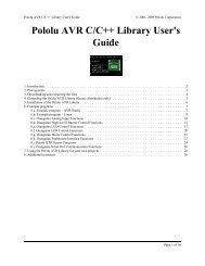
RECEIVER AND SERVO CONNECTIONSReceiver outputchannelAircraft(ACRO)Helicopter(HELI)1 Right aileron orAileroncombined right flap + aileron * orright elevon † (tailless)2 Elevator orElevatorV-tail ‡ right side orleft elevon † (tailless)3 Throttle Throttle4 Rudder orRudderV-tail ‡ left side5 Landing Gear Gyro sensitivity6 Flap orPitchcombined Left flap + aileron *Multiple entries indicate that the servo function varies with the selected programming ( * =FLPR mode,† =ELVN mode, ‡ =VTAL mode). Outputs with no mixing functions are shown first.The diagram below shows the default servo connections for a model using the ACROmode (only three or four servos are included in the T6XAs system). Two possible modelformats are shown on the ACRO contents page. Suggested helicopter connections are givenwithin the helicopter setup example.– 7 –
RADIO INSTALLATIONWhile you are installing the battery, receiver, and servos into your model’s fuselage, pleasepay attention to the following guidelines:Servo NotesMountingUse the supplied rubber grommets when you mount each servo.Be sure not to overtighten the screws. If any portion of the servo casedirectly contacts the fuselage or the servo rails, the rubber grommets will not attenuatevibration, which can cause mechanical wear and servo failure.Servo ThrowOnce you have installed the servos, operate each one overits full travel and check that the pushrod and output arms donot bind or collide with each other, even at extreme trimsettings. Check to see that each control linkage does not require undue force to move (ifyou hear a servo buzzing when there is no transmitter control motion, most likely there is toomuch friction in the control or pushrod). Even though the servo will tolerate loads like this,they will drain the battery pack much more rapidly.Switch Harness InstallationWhen you are ready to install the switch harness, remove the switch cover and use it as atemplate to cut screw holes and a rectangular hole slightly larger than the full stroke of theswitch. Choose a switch location on the opposite side of the fuselage from the engineexhaust, and choose a location where it can’t be inadvertently turned on or off duringhandling or storage. Install the switch so that it moves without restriction and “snaps” fromON to OFF and vice versa.Receiver NotesAntennaDO NOT cut or coil the receiver antenna wire. It is normal for thereceiver antenna to be longer than the fuselage.DO NOT cut it or fold it back on itself – cutting or folding changesthe electrical length of the antenna and may reduce range. Secure the antenna to the top of– 8 –
the vertical fin or the tailboom, and let the excess length trail behind the aircraft (be sure itcannot tangle with the tail rotor on a helicopter).You may run the antenna inside of a non-metallic housing within the fuselage, but range maysuffer if the antenna is located near metal pushrods or cables. Be sure to perform a rangecheck before flying. With the antenna collapsed, you should be able to walk 20 - 30 pacesfrom the model without losing control or seeing “jitter” in the servos.ConnectorsWhen you insert servo or battery connectors into thereceiver, note that each plastic housing has an alignment tab.Be sure the alignment tab is oriented properly beforeinserting the connector. To remove a connector from thereceiver, pull on the connector housing rather than the wires.Using The Aileron ExtensionIf your aileron servo (or others) are located too far awayto plug into the receiver, use an aileron extension cord toextend the length of the servo lead. Additional extension cords of varyinglengths are available from your hobby dealer or Futaba.Vibration and WaterproofingThe receiver contains precision electronic parts. Be sure to avoid vibration, shock, andtemperature extremes.For protection, wrap the receiver in foam rubber or othervibration-absorbing materials. It’s also a good idea to waterproof the receiverby placing it in a plastic bag and securing the open end of the bag with a rubber band beforewrapping it with foam. If you accidentally get moisture inside the receiver, you mayexperience intermittent operation or a crash.– 9 –
Airplane FrequenciesThe following frequencies and channel numbers may be used for flying aircraft in the U.S.:72 MHz bandCh. No. MHz 36 72.51012 72.030 37 72.53013 72.050 38 72.55014 72.070 39 72.57015 72.090 40 72.59016 72.110 41 72.61017 72.130 42 72.63018 72.150 43 72.65019 72.170 44 72.67020 72.190 45 72.69021 72.210 46 72.71022 72.230 47 72.73023 72.250 48 72.75024 72.270 49 72.77025 72.290 50 72.79026 72.310 51 72.81027 72.330 52 72.83028 72.350 53 72.85029 72.370 54 72.87030 72.390 55 72.89031 72.410 56 72.91032 72.430 57 72.93033 72.450 58 72.95034 72.470 59 72.97035 72.490 60 72.990Installing your frequency numberindicator:It’s very important that you displayyour transmitting channel number at all times.To install your indicator, peel off the channelnumber’s backing sheet, and carefully stickthe numbers to both sides of the numberholder. Now you can snap the number holderonto the lower portion of the antenna asshown in the figure – use the clip that fitsmore snugly on your antenna. You may wishto cut off the other, unused clip on theindicator.– 10 –
TRANSMITTER DISPLAYS & BUTTONSWhen you first turn on your transmitter, the screen shown below appears on the LCDdisplay. Before flying, or even starting the engine, BE SURE that the model number appearingin the lower right of the display matches the model that you are about to fly! If you don’t, servosmay be reversed, and travels and trims will be wrong, leading to an immediate crash. (If youhave trouble remembering which model memory to use, write them on a small piece of tapeaffixed to the front of the transmitter.)Startup Screen (appears when system is first turned on)ModulationindicatorPPM shownBattery voltage(Alarm goes off at 8.5V)Current model memoryModel 1 shownEdit keysMODE keys - use toselect desired functionwhile programmingPress these twokeys to enter theprogrammingmenuCURSOR key - use tostep through menu andselect item to be set orchanged in the screenDATA INPUT keys - usethese to input numbers orsettings– 11 –
WARNING DISPLAYSYour transmitter is designed to warn you about several potential problems that may occur,including low battery voltage and switching on with mixing functions active. Each display has aunique sound associated with it, as described below.Low batteryflashingWarning sound: Beep beep beep —(beeping does not stopuntil transmitter isturned off)Backup errorWarning sound: Beep beep beep beep(repeated)Mixer warningflashingWarning sound: beep beep beep pause(repeated)The LOW BATTERY warning is displayedwhen the transmitter battery voltage drops below8.5V.LAND YOUR MODEL AS SOON ASPOSSIBLE BEFORE LOSS OF CONTROLDUE TO A DEAD BATTERY.The BACKUP ERROR warning occurs whenthe transmitter memory is lost for any reason. Ifthis occurs, all of the data will be reset when thepower is turned on again.DO NOT FLY when this message isdisplayed – all programming has been erasedand is not available. Return your transmitterto Futaba for service.The MIXER warning is displayed to alert youwhenever you turn on the transmitter with any ofthe mixing switches active. This warning willdisappear when the offending switch or control isdeactivated. At power-up, warnings will beissued for the following switches:ACRO: AirbrakeHELI: Throttle hold, idle-up– 12 –
Flying SafetyTo ensure the safety of yourself and others, please observe the following precautions:Ni-cd BatteryCharge the Batteries! Don't forget to recharge the batteries before each flying session. A battery lowin charge will soon die, causing loss of control and a crash. Plug in the charger that comes in this systemand hook up the transmitter and airborne batteries the day before a planned flying session. When youbegin your flying session, keep track of how long the system’s been used, and monitor the transmitter’svoltage display. Quit flying long before your batteries become low.On-field charging of your batteries with a field charger is not recommended. A fast-charger mayovercharge the Ni-Cd batteries, causing overheating and a premature failure.Flying fieldWe recommend that you fly at a recognized model airplane flying field. You can find model clubsand fields by asking your nearest hobby dealer, or contacting the Academy of Model Aeronautics.Always pay particular attention to the flying field’s rules, as well as the presence and location ofspectators, the wind direction, and any obstacles on the field. Be very careful flying in areas near powerlines, tall buildings, or communication facilities as there may be radio interference in their vicinity. Ifyou must fly at a site that is not a club field, be sure there are no other modelers flying within a two-milerange, or you may lose control of your aircraft.Once you arrive at the flying field …Before flying, be sure that the frequency you intend to fly with is not in use, and secure anyfrequency control device (pin, tag, etc.) for that frequency before turning on your transmitter. Neverbelieve that it’s possible to fly two or more models on the same frequency at the same time. Even thoughthere are different types of modulation (AM, FM, PCM), only one model may be flown on a singlefrequency.When you are ready to fly your model, position the throttle stick to its low speed position, or dowhatever is necessary to command your motor NOT to run. Then, you may turn on the transmitter powerfollowed by the receiver power. When you have finished flying, begin by turning off the receiver power,then turn off the transmitter power. If you do not follow these procedures, you may damage your servosor control surfaces, flood your motor, or in the case of electric-powered models, the motor mayunexpectedly turn on and cause a severe injury.Before starting the engine, fully retract the transmitter antenna, power up the transmitter and receiver,and check to be sure that the servos follow the movement of the sticks. If a servo operates abnormally,don’t attempt to fly until you determine the cause of the problem. We recommend that you range-checkyour system before each flying session. Have an observer verify that the system works with thetransmitter about 30 paces away with the transmitter antenna collapsed. Finally, before starting theengine, be sure to check that the transmitter model memory is correct for the chosen model, and (for PCMreceivers only) that the fail safe system functions properly when the transmitter is shut off.While you’re getting ready to fly, if you place your transmitter on the ground, be sure that the windwon’t tip it over. If it is knocked over, the throttle stick may accidentally move causing the engine to raceunexpectedly.Before taxiing, be sure to extend the transmitter antenna to its full length. A collapsed antenna willreduce your flying range and may cause a loss of control. It is a good idea to avoid pointing thetransmitter antenna directly at the model at all times, since the signal is weakest in that direction.Don’t fly in the rain!Water or moisture may enter the transmitter through the antenna or stick openings and cause erraticoperation or loss of control. If you must fly in wet weather during a contest, be sure to cover yourtransmitter with a plastic bag or waterproof barrier.– 13 –
AIRCRAFT (ACRO) MENU FUNCTIONS*Pages 14 to 42 describe the Basic Menu functions for fixed-wing aircraft, provide adetailed setup example, and then describe the functions individually. Helicopterfunctions may be found in the following section, pages 43 to 54.Map of ACRO Menu Functions .................................................. 14Aircraft Setup Example ............................................................... 15Pattern Aircraft Trimming Chart ................................................. 22ATV ............. Adjustable Travel Volume .................................... 24D/R............... Dual Rates ............................................................. 25EXP Exponential Settings .................................................................... 26REV ............. Servo Reverse ....................................................... 27STRM .......... Subtrim.................................................................. 27FLPR............ Flaperon (combined flaps & ailerons) .................. 28FLTR............ Flap trim................................................................ 29ABRK .......... Airbrake settings ................................................... 30VTAL........... V-tail mixing ......................................................... 31ELVN........... Elevon mixing (tailless models)............................ 321 -> 4............ Rudder Coupling ................................................... 336 -> 2............ Flap -> Elevator mixing........................................ 342 -> 6............ Elevator -> Flap mixing........................................ 35PMX1, 2....... Programmable Mixer #1 & #2 .............................. 35F/S................ Failsafe function (only in PCM mode) ................. 37PARA........... Parameter menu..................................................... 38RSET............ Trim Reset............................................................. 38DRSW.......... Dual Rate Switch Select........................................ 39ACRO .......... Acrobatic model mode .......................................... 39HELI ............ Helicopter model mode......................................... 39MOD ............ Modulation (FM/PPM or PCM)............................ 40COPY........... Data Copy ............................................................. 40TMEM ......... Trim Memory........................................................ 41MODL.......... Model select .......................................................... 42– 14 –
MAP OF ACRO AIRCRAFT FUNCTIONST6XAs/Hs Acro Mode Menu [ACRO]Normal Display ModePress both ModeSelect keysThrow Adjust [ATV]Dual Rate Set [D/R]Exponential [EXP]Servo Reversing [REV]Sub-Trims [STRM]Flaperon Mix [FLPR]Flap Trim [FLTR]Airbrake [ABRK]V-Tail Mix [VTAL]Model Select [MODL]Trim Memory [TMEM]Copy Model [COPY]Parameters [PARA]Failsafe [F/S]*Prog. Mix 2 [PMX2]Prog. Mix 1 [PMX1]Elev -> Flap Mix [2-6]Flap -> Elev Mix [6-2]Memory Reset [REST]Dual Rate Sw. [DRSW]Select Model Type [ACRO]Select Model Type [HELI]Modulation: PCM or FM[MOD C or F]*Note: Failsafe menuonly appears in PCMtransmission mode.Elevon Mix [ELVN] Ail -> Rud Mix [1-4]To enter or leaveMenu, press bothMODE keyssimultaneouslyScreen at Startup– 15 –
AIRCRAFT SETUP INSTRUCTIONS (GENERAL 120 CLASS STUNT PLANE)The aircraft setup procedure presentedbelow uses a F3A-class model as an exampleits memory number prominently near its onoffswitch inside the fuselage.and assumes that there are two aileron servos,one in each wing. You may use a similarprocedure to set up your own model, but yoursetting’s numbers and percentages willprobably be different.1. Be sure that all of your servos are pluggedinto the proper receiver channels:CH1 — Aileron (Right aileron*)CH2 — ElevatorCH3 — ThrottleCH4 — RudderCH5 — GearCH6 — Flap (Left aileron*)* = if FLPR activatedWe recommend that you begin yourprogramming exercise with the servosinstalled in the model and connected to therespective control surfaces. This will enableyou to immediately see the effect of eachprogramming action we're about to take.2. Turn on your transmitter and receiver, andselect the desired model memory. To do this,enter the programming mode by pressing thetwo MODE keys, then press the down MODEkey until “MODL” appears. Press the CURSORkey and choose a vacant model memory withthe plus (+) and minus (–) DATA INPUT keys.Select it by pressing the CURSOR key until“SET” is flashing, then press both the DATAINPUT keys at once. The figure showsmemory #1 being utilized.3. Enter the Parameter (PARA, p. 38) menu bypressing the down MODE key three times.Press the key three times to select the ACROmodel type (four presses gets the HELIfunction). Select ACRO by pressing bothDATA INPUT keys. When the flashing “SET”appears, again press both DATA INPUT keys tolock it in.flashingThe reason for the separate functions withinthe PARA setup is that these are seldom used,and the parameter menu provides a convenientway of bypassing them for most programmingoperations.WARNING: selecting a different model typewill erase the settings in the model memory.BE SURE you’re in the correct modelmemory before selecting a new model type.4. If your receiver happens to be differentthan the transmission mode (as shown it’sPPM), continue to the modulation (MOD, p.40) menu to select the proper mode oftransmission (F is for FM/PPM transmission,and C is for PCM). This should be set tomatch your receiver. If you make a change, itwon’t take effect until you cycle the power offand on again. So if you have changedmodulation, cycle power now.flashingThere are a number of ways to keep track ofwhich model is in each memory. You mayattach a small piece of white tape to thetransmitter front and write the model's namealong with the model setup number, or youmay use a notebook, or label the model with– 16 –5. If your model has flaperons, turn on theFlaperon function (FLPR, p. 28) in the menu.To do this, press one of the MODE buttonsuntil “FLPR” appears in the display. Press theCURSOR key to get the “INH” flashing, thenactivate by pressing the plus (+) DATA INPUT
key (“ON” should appear flashing in thedisplay).Connect the right aileron servo to receiverCH1 and the left aileron servo to receiverCH6.aileron moves the right directions. Thedisplay shows Channel 1 reversed.Note that you can get differential by adjustingthe up and down motion of the two servos inthe FLPR menu. Now we’ll set the servo throwdirections.6. Now we’ll check that each servo moves theproper direction, and we’ll use the Reversingfunction (REV, p. 27) if they don’t.7. Next we’ll set the direction of the elevatorservo, channel 2. When you move the righthandstick towards the BOTTOM of thetransmitter, the elevator should move up.Check to make sure it moves the properdirection! (More planes are crashed due toreversed controls than for any other reason.)flashingWe’ll start by setting the right aileron servodirection. This is channel 1, and the ‘1’should be flashing for this command. Whenyou move the right-hand stick to the right, theaileron on the right wing should moveupwards, and the aileron on the left shouldmove downward. Check that the right aileronmoves the correct way!If the elevator control moves the wrongdirection, move over to Channel 2 by pressingthe CURSOR key. Now the ‘2’ should beflashing in the display. Activate the oppositedirection for the elevator servo by pressing theMinus (–) DATA INPUT key. Move the righthandstick up-and-down again and verify theelevator moves the right direction.Now we’ll set the direction of the throttleservo. When you move the left-hand sticktowards the BOTTOM of the transmitter, thethrottle should close, meaning that the hole inthe carburetor should close. Check to makesure that the throttle lever on the enginemoves the proper direction!If it does not, activate the opposite directionfor the aileron servo by pressing the DATAINPUT keys: the PLUS (+) key switches fromReversed to Normal, and the MINUS (–) keyswitches from Normal to Reversed. In thedisplay, ‘N’ for Normal is chosen when thelittle triangle is above the channel number,and ‘R’ for Reversed is chosen when the littletriangle is below the channel number. Movethe right-hand stick again and verify the rightIf the throttle servo moves the wrongdirection, activate the opposite direction forthe throttle servo by pressing the CURSORkey. Now the ‘3’ should be flashing in thedisplay. Activate the opposite direction for– 17 –
the throttle servo by pressing the Minus (–)DATA INPUT key. Verify the throttle stickmakes the servo move the carburetor openingin the correct direction.8. Now we’ll set the direction of the rudderservo. When you move the left-hand sticktowards the CENTER of the transmitter (tothe right), the trailing edge or rear ruddershould move to the right. Check to makesure!If the rudder moves the wrong direction,activate the opposite direction by pressing theMinus (–) DATA INPUT key. Move the lefthandstick left-and-right again and verify therudder moves the right direction.9. If your model has retracts, set the correctresponse direction when commanded by theretract switch, using the same approach.10. If you’re using a second aileron servo,you’ll now set the left aileron servo direction(otherwise skip this and the next step). This ischannel 6, and the ‘6’ should be flashing forthis command. When you move the righthandstick to the right, the aileron on the leftwing should move downwards. Check thatthe left aileron moves the correct way! If itdoes not, activate the opposite direction forthe aileron servo by pressing the DATA INPUTkeys. Move the right-hand stick again andverify the left aileron moves the properdirections.11. Go to the Flap Trim function (FLTR), andinput a percentage of zero (0). Then press theCURSOR key and activate the function. Thistemporarily disables the flap knob so that youcan set aileron neutrals without regard to theflap knob position. Later we’ll turn it backon.12. Now we will set the servo neutrals.Center all the trims – you can tell when eachis centered because you’ll feel a smallindentation at the center. Once you havecentered all the trims, unscrew the screwsholding the servo arms onto the elevator,aileron, and rudder (we’ll set the throttletravel later). You will want to place the servoarms on the output shaft so they are nearneutral — that is, about 90° to the servo casesides or, if the servo is mounted sideways, 90°to the pushrod (sideways mounting is notrecommended). This way you won't run outof subtrim authority. Remove all the armsthat are in the way or interfere with yourpushrods.PushrodAdjust the clevises on each servo pushrod toget the position of each control to be as closeas you can to neutral (lined up with theadjacent portion of wing or tail).13. Now we’ll set all the subtrims toelectronically set the desired neutral locations.To do so, get to the STRM menu by pressingeither MODE SELECT button repeatedly until itappears.Set the right aileron subtrim first. If the littlearrow is not pointing at channel 1, press theone of the CURSOR buttons until it is (seefigure). Then, adjust the subtrim amount byadding or subtracting with the DATA INPUTkeys. When you have reached a place whereboth ailerons match up with the fixed portionof the wing, you are done. If you can’t get– 18 –
oth to match up, then set the subtrim back tozero and mechanically adjust the clevis to getas close as you can, then readjust the subtrimif necessary.Note 1: you should NOT use subtrims insteadof mechanically adjusting the pushrods to beclose. This is because you can reduce thetravel of the radio, especially if you have toset the subtrim near 100%. As we statedbefore, get the pushrods close mechanicallyfirst, then use the subtrim adjustment to get itjust right.Note 2: if you mess up the number you’veentered or find the percentage the wrongdirection, you can get back to zero quickly bypressing BOTH the DATA INPUT keyssimultaneously.14. Repeat the subtrim adjustment with theelevator servo (Ch 2). First set the pushrodlength mechanically to get as close to neutralas possible, then set the subtrim to get theelevator lined up to be parallel with thestabilizer portion. For full-flying surfaces, usean incidence meter or another method to getthe incidence angle recommended by the kitmanufacturer or model designer.15. For the throttle, we recommend notsetting a subtrim at this time. You will use thetrim tab on the transmitter for idle andshutting off the motor, after the throwadjustments are done. You can then set thethrottle subtrim with the STRM command.The T6XAs/T6XHs automatically provides aspecial function called Adjustable TravelLimit. This function makes the trim work atlow throttle levels, but disables it at highthrottle. Most people set up their engines toidle with the throttle trim near center, andhave the engine quit when they move the trimto the bottom position. You’ll set this up laterin the Travel volume settings.16. Repeat the subtrim adjustment with therudder, gear, and 2nd aileron channels. Asbefore, first set them mechanically, thenadjust the electronic settings. Be sure youhave selected CH4, CH5, or CH6 respectively.17. Now we’ll go through and set the servotravels for each channel. This is both helpfuland important, because you can set the throwof each servo, in each direction, so that thereis no binding. Binding is important because itcauses very high current drain, and can lead toa battery dying prematurely.To set travels, get to the ATV menu bypressing the MODE SELECT button repeatedlyuntil it appears. In sequence, we’ll set Rightaileron right travel, right aileron left travel, upand down elevator travels, right and leftrudder travels, open and closed throttlepositions, and left aileron travels.Changes to"L/D" with AILstick motionflashingWhen you reach the ATV menu, you’ll see thescreen as shown. The channel indicator isbelow numeral 1 for right aileron, the percentsymbol will be flashing, and you’ll notice thatyou can change the L/D indicator to R/U (orvice versa) by moving the aileron (right) stick.You are about to see that this is how you setthe travel directions independently for eachstick motion.18. To set the RIGHT aileron motion, movethe aileron stick all the way to the right andhold it. The letters “R/U” should appear nextto the flashing percent sign, meaning you aresetting either Right or Up travel (with aileronsit’s right or left only, but the display is set upto use the same indicators for elevator andthrottle, thus the dual meanings for theletters). Now if your servo is stalled orbinding, you’ll hear a buzzing sound. Hit theminus DATA INPUT key until the buzzingstops. If the servo is not buzzing, leave thesetting at 100%. Choose a location on the– 19 –
servo arm so that the throw is adjusted in the90-100% range.19. To set the right aileron’s LEFT motion,move the aileron stick all the way to the leftand hold it. The letters “L/D” should appearnext to the flashing percent sign (as shown inthe figure above). Again listen and hit theminus DATA INPUT key until the buzzingstops. If the servo is not buzzing, leave thesetting at 100%. You may wish to increase ordecrease this number depending on howrapidly the model rolls to the left. Onepossible setting is roughly 9/16” (14-15 mm)travel in both directions. (Remember, you’reonly setting the right aileron if you have theflaperon function turned on. You set the otheraileron’s travel in channel 6’s ATV.)20. To set the UP elevator motion, press onthe CURSOR key until the indicator movesunderneath channel 2, as shown. Now movethe right stick all the way to the transmitterbottom and hold it. The letters “R/U” shouldappear next to the flashing percent sign (asshown in the figure above). Again listen for abuzzing sound to indicate the servo is stalling,and hit the minus DATA INPUT key until thebuzzing stops. If the servo is not buzzing,leave the setting at 100%. You may wish toincrease or decrease this number depending onhow tightly the model does an inside loop (orwhether it snap rolls when it shouldn’t).Changes to"L/D" with AILstick motionflashing21. Repeat the previous step for DOWNelevator by moving the stick all the way to thetop of the transmitter, full “down” elevator.Check for binding and adjust the percentageas before. The elevator settings should beadjusted so that the elevator travel is roughly9/16” (15 mm).22. To set the throttle position at IDLE, presson the CURSOR key until the indicator movesunderneath channel 3. Now move the throttlestick all the way to the transmitter bottom andhold it. The letters “R/U” should appear nextto the flashing percent sign. Listen for abuzzing sound to indicate the servo is stalling,and hit the minus DATA INPUT key until thebuzzing stops. If the servo is not buzzing,leave the setting at 100% or increase it asnecessary to fully close the throttle. You maywish to increase or decrease this numberdepending on whether you can shut off theengine using throttle at idle and the trim tab.23. To set the FULL throttle position, movethe throttle stick all the way to the transmittertop and hold it. The letters “L/D” shouldappear next to the flashing percent sign.[Notice that the T6XAs/XHs transmitterthinks of throttle stick positions to the reverseof the way it seems, in that with the throttlestick fully forwards — “up” towards thetransmitter top, is the Down position.] Listenfor a buzzing sound to indicate the servo isstalling, and hit the minus DATA INPUT keyuntil the buzzing stops. If the servo is notbuzzing, leave the setting at 100% or change itas necessary to fully open the throttle.24. To set the RIGHT rudder motion, presson the CURSOR key until the indicator movesunderneath channel 4. Now move the leftstick all the way to the transmitter right andhold it. The letters “R/U” should appear nextto the flashing percent sign. Listen for abuzzing sound to indicate the rudder servo isstalling, and hit the minus DATA INPUT keyuntil the buzzing stops. If the servo is notbuzzing, leave the setting at 100%. You maywish to increase or decrease this numberdepending on how strongly the model reactswhen the rudder is deflected. Now move thestick to the left side, and repeat the settingprocedure for left rudder. The rudder travelshould be set to roughly 45 degrees on bothsides.23. In the same manner as described above,be sure to set ATV values for channels 5(landing gear) and 6 (second aileron), if youhave either.– 20 –
If you wish to have the flaps operate with theCH6 knob, go back to the FLTR menu andinput a number greater than zero. Adjust thenumber to get the desired amount of flaptravel as you turn the knob.If you wish to have differential in yourflaperons, go to the flaperon menu and reducethe number to something less than 100%. Ifyou choose 0%, you’ll get only up aileronmotion.24. One more basic function that you willfind extremely useful is the trim memoryfunction. This is used after the model istrimmed out and flying the way you like.Unless you build perfectly, after test flyingand trimming one or more of the trim tabs willbe off-center. This is not a problem if you areonly flying one model with the T6XAs/XHstransmitter and you never accidentally moveone or more of the trim tabs, but if you haveseveral models in memory or do accidentallymove on or more of the tabs, all the trimscould be different. The trim memory functionsolves this problem by memorizing the offsetsfor each model in memory.To use the Trim Memory function, press onthe MODE SELECT button until TMEM appearson the menu. You will see the display shown.Trim memory is quite easy to use: with thetrim tabs in the desired position, simply pressboth DATA INPUT keys at the same time, andthe trim positions are stored. Now, however,you must move the trims back to their neutralposition, or else the offsets will be doubled,and you don’t want that. Simply move thetabs until you feel the detent at each one’scenter. If you do this with each of the modelsstored in memory, you will know the model istrimmed when the trims are centered. [Notethat the throttle trim position is not memorizedif you are in the ATL mode. This is so you canalways use the trim to shut the motor off.– 21 –flashingResetting Trim Memory: if you want to zeroout the trim memory, you have to go to theTMEM setting menu, and observe the marksover or under the channel numbers 1 2 4. Ifthe trim memory has a non-zero value(meaning you memorized a trim setting), alittle triangle will appear over thecorresponding channel. Now move the trimtab for that channel until the triangledisappears — this is the nominal neutral trim.Repeat for the other channel numbers. Whenyou've done all three, hit the DATA INPUT keyssimultaneously, then center the trim tabs.You've initialized the trims.25. Aileron Dual Rate setting (D/R, p. 25).You can use the dual rate function to reducethe aileron and elevator travel in flight byflipping one or two switches. Press a MODESELECT key repeatedly until the D/R menuappears, as shown.lower arrowindicateslower switchsettingflashingDual rates are typically used to reduce amodel’s sensitivity, but they can also be usedto increase it.To set the aileron dual rate (although this isset for CH1, it affects both ailerons if theflaperon function is active), move the arrowby pressing the CURSOR key until the littlearrow is under or over the numeral 1. Nowmove the aileron D/R switch up or down,noticing the position of the arrow. You canset two dual rates, one for each switchposition. By pressing the DATA INPUT keys,you can add or subtract from the numericalvalue displayed. Note that you may pick avalue anywhere from 0% to 120% (120% islarger than the normal amount, so if you dothis be careful not to exceed servo travel limitsand cause stalling or excess current drain). If
you quickly want to get back to the default100%, press both DATA INPUT keyssimultaneously. We suggest using an initialvalue of 75%, which will limit the ailerontravel to roughly 7/16” (11 mm).NOTE: if you set the dual rate to 0%, you willhave ZERO CONTROL AUTHORITY whenthe switch is in that position. DON’T DO IT!26. Elevator dual rate setting: press theCURSOR key one time to get the little arrowsabove or below the numeral 2. Now set theelevator dual rates in the same way you set theailerons. Adjust the up elevator travel to beabout 15/32” (12 mm) and the down elevatortravel to 17/32” (13 mm).27. There is an option on the T6XAs/XHswhich allows you to put both dual rateswitches on the aileron D/R switch, or to keepthem on separate switches. This option is thesecond item located in the PARA menu.travel so that there is minimal trim changewhen the airbrake switch is operated.Press the MODE SELECT button until the ABRKwindow appears, as shown. The default is forthe airbrake mode to be inhibited, as shown.To activate, press the CURSOR key until the“INH” is flashing, then press the (+) key.Set mode withDATA INPUTkeys:+ = Activate- = InhibitNow press the CURSOR key one time, and thepercent symbol will flash. You may input theamount of offset for the elevator (the arrowshould be under the numeral 2) at this time.This should be set from -7% to -10% (-10% isthe default setting).Press the CURSOR key one more time, andyou may now input the CH6 setting. The ratesmay vary considerably for different models,but for initial settings choose the flap rate tobe (+)50-55%.OFF sideON sideAIR BRAKEIf you choose the ‘2’ option as shown, bothdual rates will be operated by the aileron dualrate switch. If you choose the ‘1’ option, thetwo D/Rs will operate off their individualswitches. We suggest the ‘2’ option as it’sone less switch to keep track of.28. Airbrake (ABRK, p. 30): an airbrake effectis obtained by raising both ailerons (ordropping the flaps) and adding elevator totrim. This high-drag configuration makes thelanding approach steeper to help make safelandings in small fields. With this function, itis possible to lose some aileron effectivenessso test the airbrake effect at altitude beforetrying it on a landing approach. You shouldspend some time fine adjusting the elevatorON or OFF indicatesAirbrake switch position. Increase or decreaseamount of travel withDATA INPUT keys29. Failsafe settings: we recommend that youset the Fail Safe function (F/S, p. 37) to movethe throttle to idle if interference isexperienced. Note that the failsafe functiononly operates in the PCM transmission mode.30. 2->6 Mixing: you may couple elevator toflaps for tighter corners in the elevator-to-flapmixer (2 -> 6, p. 35). Get to the 2->6 menu,then activate it by pressing the CURSOR key,then the (+). Pull up elevator and verify thatthe flaps go down. If they go the wrongdirection, reverse them by pressing the (+) or– 22 –
(–) keys until they do go the right direction.Then press the CURSOR key again, and thepercent indicator will flash. Now you mayinput the percentage of mixing. Start out with10-20% and increase it until the corners inyour loops are square enough.31. Programmable mixers: now takeadvantage of your system’s customprogramming capabilities. You may useprogrammable mixers (PMXI or PMX2, p. 35)to get rid of unwanted tendencies (forexample, pitching up during knife-edge flight.For pitching during knife-edge, you want toapply up or down elevator when you are usingfull rudder to sustain knife-edge. Thus, themaster channel is rudder, and the slave iselevator.To program this mixing, first get to the PMXIwindow. Press the CURSOR key once, thenpress the (+) to activate it (a flashing ON orOFF will appear, depending on the position ofthe Elev D/R switch, which turns mixer #1 onand off).Next, press the CURSOR key once, then pressthe DATA INPUT key until the little arrow isover the numeral 4, indicating CH4 (rudder) isthe master channel. Press the CURSOR keyonce, then press the DATA INPUT key until thelittle arrow is under the numeral 2, indicatingCH2 (elevator) is the slave channel.Now, you’ll define the mixing direction. Ifyour model pitches up with knife edge, you’llwant to input down elevator for rudder goingboth directions. Move the rudder stick to oneside and see which way the elevator moves; ifincorrect, press the CURSOR key once, thenpress the DATA INPUT keys until it movesdown. Repeat this by moving the rudder stickto the other side. You’ll end up with a plussign for one rudder direction, and minus forthe other direction.Finally you may input the amount of elevatormixing on both sides by pressing theCURSOR key, then the (+) or (–) keys until asmall amount of mixing has been assigned.Repeat this by moving the rudder stick to theother side and verifying that the numbersmatch for both directions.Be sure you understand how to use the ElevD/R to switch to turn the mixer on and off,since you won’t want this mixing on duringnormal flight, only during knife-edge. Later,after you fly the model you may fine tune theamount of elevator travel so that the pitchingtendency is eliminated.The sky’s the limit — you’ll enjoy using yourT6XAs/XHs system!Pattern Aircraft Flight Trimming ChartThe following chart may be used to systematically set up and trim a model for straight flight andaerobatic maneuvers. Please note that for best results, trimming should be done in near-calmconditions. Before you decide to make a change, be sure to try the test several times beforemaking adjustments. If any changes are made, go back through the previous steps and verifythat they are not also affected. If they are, make further adjustments as necessary.To test for … Test Procedure Observations Adjustments1. ControlneutralsFly the model straight andlevelUse the transmitter trims for hands-offstraight & level flight.Change electronic subtrims oradjust clevises to centertransmitter trims.– 23 –
2. Control throws Fly the model and apply fulldeflection of each control inturn3. Decalage Power off vertical dive(crosswind if any). Releasecontrols when model vertical(elevator trim must be neutral)4. Center ofGravity5. Tip weight(coarseadjustment)6. Side Thrust &Warped Wing7. Up/DownThrust8. Tip weight(fine adjustment)9. AilerondifferentialMethod 1: Roll into nearvertically-banked turn.Method 2: Roll model invertedFly model straight & levelupright. Check aileron trimmaintains level wings. Rollmodel inverted, wings level.Release aileron stick.Fly model away from you intoany wind. Pull it into avertical climb, watch fordeviations as it slows down.Fly the model on normal pathinto any wind, parallel to strip,at a distance of around 100meters from you (elevator trimshould be neutral as per Test3). Pull it into a vertical climb& neutralize elevatorMethod 1: fly the model as perTest 6 and pull into areasonably small diameterloop (one loop only)Method 2: fly the model as perTest 6 and then push into anoutside loop (one only, fairlytight)Method 1: fly model towardyou & pull into a verticalclimb before it reachesyou. Neutralize controls,then half-roll the model.Method 2: fly model onnormal pass and do three ormore rollsMethod 3: fly the modelstraight and level andgently rock the aileronstick back and forthCheck the response of each control• Aileron high-rate: 3 rolls in 4 seconds;low-rate: 3 rolls/6 sec• Elevator high-rate: to give a smoothsquare corner; low-rate gives approx.130 ft diameter loop• Rudder: high-rate 30-35° for stallturns; low rate maintains knife-edgeA. Model continues straight downB. Model starts to pull out (nose up)?C. Model starts to tuck in (nose down)?A1. Nose dropsB1. Tail dropsA2. Lots of forward stick (downelevator) required to maintain levelflightB2. No forward stick (down elevator)required to maintain level flight, ormodel climbsA. Model does not drop a wing.B. Left wing drops.C. Right wing drops.A. Model continues straight up.B. Model veers leftC. Model veers rightD. Model rolls rightA. Model continues straight upB. Model pitches up (goes toward top ofmodel)C. Model pitches down (goes towardbottom of model)A. Model comes out with wings levelB. Model comes out right wing lowC. Model comes out left wing lowA. No heading changesB. Heading change opposite to rollcommand (i.e. heading veers leftafter right roll)C. Heading change in direction of rollcommandA. Roll axis on model centerlineB. Roll axis off to same side of modelas roll command (i.e. right roll, rollaxis off right wing tip)C. Roll axis off to opposite side ofmodel as roll commandA. Model flies straight ahead withoutyawingB. Model yaws away from rollcommand (i.e. right roll, yaw left)C. Model yaws towards roll command(i.e. right roll, yaw right)Change ATV (for high rates),and Dual Rate settings (forlow rates) to achieve desiredresponses.A. No adjustmentB. Reduce incidenceC. Increase incidenceA. Add weight to tailB. Add weight to noseA. No adjustmentB. Add weight to right tip.C. Add weight to left tip.A. No adjustmentB. Add right thrustC. Reduce right thrustD. Put trim tab under leftwing tip *A. No adjustmentB. Add down thrustC. Reduce down thrustA. No adjustment necessaryB. Add weight to left tipC. Add weight to right tipA. Differential settings OKB. Increase differentialC. Decrease differentialA. Differential settings OKB. Increase differentialC. Decrease differentialA. Differential settings OKB. Increase differentialC. Decrease differential– 24 –
10. Dihedral Method 1: Fly the model onnormal pass and roll intoknife-edge flight; maintainflight with top rudder (do thistest in both left & right knifeedgeflight)Method 2: Apply rudder inlevel flight11. Elevatoralignment (formodels withindependentelevator halves)12. Pitching inknife-edge flightFly the model as in Test 6 andpull up into an inside loop.Roll it inverted and repeat theabove by pushing it up into anoutside loop.Fly the model as in Test 10A. Model has no tendency to rollB. Model rolls in direction of appliedrudderC. Model rolls in opposite direction inboth testsA. No rolling tendency when elevatorappliedB. Model rolls in same direction in bothtests — halves misaligned.C. Model rolls opposite directions inboth tests. One elevator half hasmore throw than the other (modelrolls to side with most throw).A. There is no pitch up or downB. The nose pitches up (the modelclimbs laterally)C. Nose pitches down (model diveslaterally)A. Dihedral OKB1. Reduce dihedralB2. Use mixer to produceaileron opposing ruddertravel (start with 10%)C1. Increase dihedralC2. Mix ailerons with rudderdirection 10%A. Elevators in correctalignmentB. Either raise one half, orlower the otherC. Reduce throw on one side,or increase throw on theother.A. No adjustment neededB. Alternate cures:1) move CG aft;2) increase incidence;3) droop ailerons;4) mix down elevator withrudderC. Reverse ‘B’ above*Trim tab is 3/16” x 3/4” x 4” trailing edge stock, placed just in front of aileron on bottom, pointed end forward.– 25 –
ATV — Adjustable Travel VolumeThe ATV function is used to set (or limit) the travel of each servo, and maybe set independently between a value of 10% and 120% for each traveldirection. At a 100% setting, the throw of the servo for full stick motion isapproximately 40° for channels 1 – 4 and approximately 55° for channels 5 – 6. Reducing thepercentage settings reduces the total servo throw in that direction. The ATV function is normallyused to prevent any servos from binding at the ends of their travel.Setting ATV values on your system:1. Enter the programming mode, and get to the ATV screen with the up ordown arrow keys. The channel indicator is below numeral 1 for ailerons,the percent symbol will be flashing, and you’ll notice that you can changethe L/D indicator to R/U (or vice versa) by moving the aileron (right) stick.In Steps 2 & 3 you will see how you set the travel directions independently for each stick (orknob or gear switch) motion.2. To set the RIGHT aileron motion, move the aileron stick all the way to the right and hold it.The letters “R/U” should appear next to the flashing percent sign, meaning you are settingeither Right or Up travel (with ailerons it’s right or left only, but the display is set up to usethe same indicators for elevator and throttle, thus the dual meanings for the letters). Now ifyour servo is stalled or binding, you’ll hear a buzzing sound. Hit the minus DATA INPUT keyuntil the buzzing stops. If the servo is not buzzing, leave the setting at 100%. Later, afterflying the model, you may wish to increase or decrease this number depending on howrapidly the model rolls to the right (you may also use dual rates to reduce your model’sresponses).3. To set the LEFT aileron motion, move the aileron stick all the way to the left and hold it.The letters “L/D” should appear next to the flashing percent sign. Again listen and hit theminus DATA INPUT key until the buzzing stops. If the servo is not buzzing, leave the settingat 100%. You may wish to increase or decrease this number depending on how rapidly themodel rolls to the left (or use dual rates as mentioned before).4. To set travel volumes for other channels, press the CURSOR key to selectthe channel you wish to change. The little triangle moves and indicates theactive channel. Repeat steps 1-3 with each channel in sequence, taking care to set the travelfor both directions.5. You may set each channel separately, anywhere in between 10% and 120%, and if you wishto rapidly return to the default 100% setting, press both the (+) and (–) keys simultaneously.– 26 –
D/R — Dual RatesIf this is your first computer radio, you may have never been introduced to dual ratesbefore. Dual rates are used because most models respond more rapidly to control inputs whilethey’re flying at higher speeds, and it is possible to be really gentle with the controls and yet stillover-control. Dual rates are used to adjust the transmitter so that a control actuated at high speedwill not cause a radical response, so they are very useful for beginning pilots as well as experts.Dual rates are invoked by flipping a switch on the transmitter. The T6Xs/XHs has twodual rate switches, one each for elevator and ailerons. The aileron dual rate switch is locatedover the right-hand stick, and the elevator dual rate switch is located over the left-hand stick. Ifyou prefer to have both operate on a single switch, you may combine them to both operate on theaileron dual rate switch in the DRSW window (within the PARA menu).You can use D/R dual rate settings to reduce (or increase) the aileron and elevator servotravels by flipping a switch. The amount of travel reduction or increase may be set anywherebetween 0 and 120% Note: if you set the dual rate amount to zero, you will get no responsefrom that channel, which may cause a crash.Inputting Dual Rate Values1. Get to the D/R screen with the up or down arrow keys.2. Use the CURSOR key to select the channel (aileron, elevator or rudder)you wish to reverse. The active channel number is indicated by the arrowabove or below. The arrow’s position depends on the position of thatchannel’s dual rate switch. In the figure, the aileron (CH1) dual rate setting at the D/Rswitch’s lower position is being programmed.D/R Sw.Mode 1D/R Sw.Mode 2(combined switch)3. Choose the amount of dual rate with the (+) or (–) keys. You may set the travel for bothsides of the switch simply by flipping the switch to the other position (the arrow will alsoswitch sides). If you wish to return to the original 100% value, press both keyssimultaneously.4. Repeat this procedure for the dual rate settings on the other channel remaining.– 27 –
EXP — Exponential SettingsExponential settings may be used to changes the response curve of the servos to makeflying more pleasant. You can make the servo movement less or more sensitive around neutralfor aileron, elevator, throttle (except HELI type), and rudder. It can also be set for each side ofthe dual rate switches. Negative exponential (-) makes the servo movement around the stickneutral less sensitive and positive (+) makes the servo movement more sensitive.For throttle, exponential is applied from the end of travel rather than for neutral like theother controls. When the (-) side is increased, the idle sensitivity decreases and the high throttlesensitivity increases. This is best understood by experimenting with a servo.Inputting Exponential Values1. Get to the EXP screen with the up or down arrow keys.2. Use the CURSOR key to select the channel (aileron, elevator, throttle orrudder) you wish to change the response curve. The active channelnumber is indicated by the arrow above or below. The arrow’s positiondepends on the position of that channel’s dual rate switch. In the figure, the aileron (CH1)exponential setting at the D/R switch’s lower position is being programmed.3. Choose the amount of exponential with the (+) or (–) keys. You may set the amount for bothsides of the switch simply by flipping the switch to the other position (the arrow will alsoswitch sides). If you wish to return to the original 0% value, press both keys simultaneously.4. Repeat this procedure for the exponential settings on the other channel remaining.– 28 –
REV — Servo ReversingThe servo reverse function may be used when you need to change the direction that aservo responds to a control stick motion. When you use this function, BE SURE THAT YOURCONTROL IS MOVING THE CORRECT DIRECTION. If you are using any preprogrammedmixers such as flaperon, be sure to set correct travels in the REV menu setting up thepreprogrammed function.Reversing Servos1. Get to the REV screen with the up or down arrow keys.2. Use the CURSOR key to select the channel you wish to reverse. Theactive channel number will flash.3. Select normal (N) with the (+) key, or select reverse (R) with the (–) key.The arrow above the number indicates normal travel, while the arrow below indicatesreversed travel (the figure shows all channels normal, none reversed).4. Repeat this procedure for each channel needing to be reversed.STRM — Subtrim SettingsThe Subtrim window is used to make small adjustments or corrections in the neutralposition of each servo. The recommended procedure is to zero out both the trims (see TMEMmenu) and the subtrims (this menu). Next, mount the servo arms and set up your linkages so thatthe neutral position of each control surface is as close to where it should be as possible, with thearm 90° to the pushrod. Finally, use a small amount of subtrim to make fine corrections. Werecommend that you try to keep all of the subtrim values of as small as possible. Otherwise,when the subtrims are large values, the servo’s full range of travel may be restricted.Setting Subtrims1. Use the up or down arrow keys to call up the STRM window.2. Press the CURSOR key until the small arrow is underneath the channelyou wish to adjust (the figure shows subtrim adjustment for CH1).3. Adjust the neutral position using the (+) or (–) keys. You may adustbetween -120% and +120%. If you want to reset the value back to zero, press both the (+) and(–) keys simultaneously.4. Repeat steps 2 and 3 for each channel to be adjusted in turn.– 29 –
FLPR — Flaperon MixingThe Flaperon mixing function uses two servos to individually control two ailerons,combining the aileron function with the flap function. Both ailerons can be raised and loweredsimultaneously for a flap effect. Of course, aileron function, where the two controls move indifferent directions, is also performed. The down travel of the left and right ailerons can beadjusted, so you can also get a differential effect. (Left and right flap travel are adjustedindividually in the ATV menu.) To take advantage of the flaperon mixing function, you’ll needto connect the right aileron servo to CH1 (AIL) and the left aileron servo to CH6 (FLP).Ch 1 Ch 6Aileron OperationCh 1 Ch 6Flap OperationYou can combine the flaperon function with the airbrake function (ABRK), to get steeperdescents without building up airspeed. This is very convenient for making short approaches onsmall fields.Please note that you may only use one function from flaperon, elevon, or V-tail at a time.The one you activate overrides the others. If you need V-tail with a flaperon model, use theprogrammable mixers (PMXI & PMX2) to program in the V-tail function.Setting up the Flaperon function1. Use the up or down arrow keys to select the FLPR window.2. When first accessed, the flaperon function is inhibited (INH). Press theCURSOR key to get to the activation menu. The INH indicator will flash on and off.3. Now press the (+) key to activate the flaperon function. At this time, the ON indicator willblink on and off.4. Next you may set aileron differential. Aileron differential meansthat one aileron has more travel in one direction than the otherdirection. Normally the down travel is reduced to about half ofthe up travel, especially on slower-flying models.Pressing the CURSOR key one time causes the large sign in front of the number to blink.You may reduce the down travel by selecting the minus (–) sign. If you choose 0% down,the ailerons will move up only. This is preferred over reducing the up travel.5. Pressing the CURSOR key again moves to the differential setting number (the percent signshould now be flashing). For the 100% value, the up and down travel are both the same.Reducing to less than 100% causes less travel. 50 - 75% is a good starting value, but observeyour model in flight to fine tune this setting. If you wish to return to 100%, press both the(+) and (–) keys simultaneously.– 30 –
FLTR — Flap Trim FunctionThe Flap Trim function is used to specify the amount of flap travel produced by movingthe flap control (the CH6 knob). If flaperon (FLPR) function has been activated, FLTR isautomatically turned on. Sailplane folks call this effect “camber,” because the model’s airfoil ischanged across the span.Setting Flap Trim function1. Use the up or down arrow keys to select the FLTR window.2. Press the CURSOR key to get to the activation setting. The INH indicatorwill flash on and off.3. Now press the (+) key to activate the flap trim function. At this time, theON indicator will blink on and off.4. Now you’ll set the flap knob’s travel direction. This is similar to the reversing menu, but itreverses the response of both flaperons if flaperon mode is active.Pressing the CURSOR key one time causes the large sign in front of the number to blink. Youmay reverse the travel direction by selecting the minus (–) sign.5. Pressing the CURSOR key again moves to the flap travel setting number (the percent signshould now be flashing). The 30% default value produces “reasonable” travel for many models,but you must try it out on your own model to be sure. A 100% setting causes extreme travel andis not recommended. You may want to set it to a smaller number, say 10% for starters. If youwish to return to the default 50% setting, press both the (+) and (–) keys simultaneously.– 31 –
ABRK — Airbrake FunctionThe ABRK function, when activated, simultaneously moves the flaps and offsets the elevator,and may be used to make steep descents or limit airspeed in dives. All the controls move to thedefined positions by flipping the airbrake switch downwards. Normally, with a single flap, theflap is dropped. With flaperons, you’ll want to raise both to prevent tip-stalling, but you mayexperiment with small values of down flaperons to slow the model down.When the airbrake function is active, both ailerons’ travel is set by a single number. Theelevator offset should be chosen to maintain trim when the airbrake function is turned on and theailerons rise.Setting up Airbrake function1. Use the up or down arrow keys to select the ABRK window.2. Press the CURSOR key twice to get to the activation setting. The INHindicator will flash on and off.3. Now press the (+) key to enable the airbrake function. Depending on theposition of the airbrake switch, the display will show a flashing OFF or ON.4. First the amount of elevator offset is programmed. Press the CURSOR onetime. A small arrow is displayed under the numeral 2 (representingelevator), and the percent sign will blink on and off. You may adjust the amount of travelwith the (+) and (–) keys. You may use anywhere between -100% and +100%, but thedefault value of -10% is the recommended starting value. Be careful setting elevator offset,as this has a very powerful effect on the model’s trim. Press both the (+) and (–)simultaneously if you wish to reset to -10%.5. To get to the flap travel setting, press the CURSOR key. A small triangle isnow displayed underneath the numeral 6, indicating the flap channel. Inaddition, the percent indicator will flash on and off. You may input any desired flap travelwith the (+) and (–) keys. Although the default is -50%, you may set this anywhere from -100 to +100%. You may return to the default settings by hitting both the (+) and (–) keystogether.Note: if you have the flaperon function active, the ABRK function will cause both flaperons tomove. Be very cautious with large flap settings, as they may reduce the aileron authoritywhen you are flying slowly.– 32 –
VTAL — V-Tail MixingV-tail mixing is used with V-tail aircraft so thatboth elevator and rudder functions are combined for thetwo tail surfaces. Both elevator and rudder travel can beCh 2Ch 4 Ch 2 Ch 4Up ElevatorLeft Rudder (view from rear)adjusted independently. However, if you program in too much elevator or rudder travel, whenboth rudder and elevator are commanded the servos may reach their travel limits before full stickmotion has occurred. Therefore, you should keep the travel settings at 50% or below and adjustthe control linkages to get the travel you desire.Please note that you may only use one function from flaperon, elevon, or V-tail at a time.The last one activated has priority. If you need V-tail with a flaperon model, use theprogrammable mixers (PMXI & PMX2) to program in the V-tail function.Setting up V-Tail mixing1. Use the up or down arrow keys to select the VTAL window.2. Press the CURSOR key three times to get to the activation setting. The INHindicator will flash on and off.3. Press the (+) key to enable the V-tail function. The display will show a flashing ON.4. Press the CURSOR key once, to get to the elevator setting menu. A smallarrow is displayed over the numeral 2 (representing elevator), and the plusor minus sign above the large setting number will blink on and off.Pull back on the elevator stick: both sides of the V-tail should move upwards. If they don’t,you may change the elevator travel direction with the (+) and (–) keys. Note that thisreverses the response at both V-tail servos (not just one as in the REV menu). If only oneservo moves up, reverse the other one in the REV menu.5. Now you’ll input the amount of elevator travel by pressing the CURSOR key once. Now thepercent sign will blink on and off, and you may adjust the amount of elevator travel with the(+) and (–) keys. You may change the initial 50% setting to be anywhere between 0% and100% (press the plus and minus keys together if you wish to reset to 50%).6. Next: the rudder inputs. Press the CURSOR key once. A small arrowshould appear over the numeral 4 in the screen, and the sign in front of thelarge setting number will flash on and off. Holding left rudder stick, verifythat the servos move the correct direction (see figure). If they move incorrectly, change thedirection by pressing the (+) or (–) key which changes the flashing sign displayed.7. Now input the amount of rudder travel. Press the CURSOR key once; the percent sign willblink on and off. You may adjust the amount of rudder with the (+) and (–) keys, changingthe initial 50% setting to be between 0% and 100% (press the (+) and (–) keys together if youwish to reset to 50%). Remember to be sure not to have so much travel as to cause bindingwhen both elevator and rudder are commanded simultaneously.– 33 –
ELVN — Elevon MixingThe Elevon function should be used with delta wings, flying wings,and other tailless aircraft whose layouts combine the aileron and elevatorfunctions, and requires one servo for each elevon. Connect the rightaileron to receiver CH1/AIL and the left aileron to CH2/ELE.The amount of aileron and elevator response can be adjustedindependently. However, if you program in too much elevator or ruddertravel, the servos may reach their travel limits before full stick motion hasoccurred. Therefore, you should keep the travel settings at 50% or belowand adjust the control linkages to get the travel you desire.2CH1CHAileron operationElevator operationNOTE: The elevon, V-tail, and flaperon functions cannot be activated simultaneously.The function activated last has priority.Setting up elevon mixing1. Use the up or down arrow keys to select the ELVN window.2. Press the CURSOR key three times to get to the activation setting. The INHindicator will flash on and off.3. Now press the (+) key to enable the elevon function. The display willshow a flashing ON.4. Press the CURSOR key once, to get to the aileron setting menu. A smallarrow is displayed over the numeral 1 (representing aileron masterchannel), and the plus or minus sign above the large setting number willblink on and off.Move the aileron stick all the way to the right: the right elevon should move upwards, andthe left elevon should move downwards. If they move opposite to this, change the ailerontravel direction with the (+) and (–) keys. Note that this reverses the response at both elevonservos (not just one as in the REV menu). If both servos move the same direction, reversethe one that moves improperly in the REV menu.5. Now you’ll input the amount of aileron travel by pressing the CURSOR key once. Now thepercent sign will blink on and off, and you may adjust the amount of aileron travel with the(+) and (–) keys. You may change the initial 50% setting to be anywhere between 0% and100% (press the plus and minus keys together if you wish to reset to 50%).6. Next: the elevator inputs. Press the CURSOR key once. A small arrowshould appear over the numeral 2 in the screen (indicating elevator is themaster channel), and the sign in front of the large setting number will flashon and off. Verify that when you pull back on the elevator stick, both the elevon servosmove upwards. If they move the incorrect direction, change the direction by pressing the (+)or (–) key which changes the flashing sign displayed.7. Now you’ll input the amount of elevator travel by pressing the CURSOR key once. Now thepercent sign will blink on and off, and you may adjust the amount of elevator travel with the(+) and (–) keys. You may change the initial 50% setting to be anywhere between 0% and100% (press the plus and minus keys together if you wish to reset to 50%). Remember to besure not to have so much travel as to cause binding when both elevator and aileron arecommanded simultaneously.– 34 –
1->4 — Aileron -> Rudder MixingAileron-to-rudder mixing is a function which causes the rudder to move automaticallywith the motion of the aileron stick. This is done because when ailerons are used to command aturn, the down-moving aileron has more drag than the up-moving one, so the plane’s fuselagetries to yaw against the turn. Adding rudder mixing cures this problem by making the fuselagepoint straight into the oncoming air stream (this is also called “coordinating the turn”).The slower the model flies, the more mixing is needed, and the faster it moves, the less isneeded. It is ideal to make slow-flying scale models fly realistically. The amount of coupling ishighly dependent on the model configuration. Usually only a small amount of rudder is needed,especially if a large amount of differential (more up aileron motion than down motion) ispresent.Nose points outsidecircle: increase couplingand/or differentialCoordinated turn: fuselines up with turn direction(don't change anything)Nose points insidecircle: too much couplingor differential. Reduce oneor both.Setting Up 1->4 Mixing (Rudder Coupling)1. Use the MODE buttons until the 1->4 window appears, as shown. Thedefault is for the function to be inhibited, as shown. To activate, press thepress CURSOR key once, then press the (+) DATA INPUT key. The flashingletters “INH” will turn to “ON.”2. Press the CURSOR key once, and the plus or minus sign in front of the number will flash.Move the aileron stick to the right (or left). If the rudder moves the same direction, proceedto the next step. Otherwise, change the sign in front of the number by pressing one of theDATA INPUT keys.3. Press the CURSOR key once, and now the Percent sign will be flashing. Move the aileronstick all the way to the right, and adjust the mixing amount by pressing the DATA INPUT keys.You may set any amount between 0 and 100%. To return to the initial 50% value, pressingboth DATA INPUT keys.– 35 –
6->2 — Flap -> Elevator MixingFlap-to-elevator mixing trims the elevator to compensate for trim changes when the flapsare commanded to drop or rise. This usually requires a relatively small amount of elevatortravel. The mixing point may also be offset to match the neutral flap position.Inputting settings for 6 -> 2 mixing1. Press one of the MODE buttons until the 6->2 window appears. Thedefault is for the function to be inhibited. Press the CURSOR key twice tomake the INH display flash on and off. To activate, press the (+) DATAINPUT key. The ON display should flash on and off.2. Press the CURSOR key once. At this time, the plus or minus sign in front of the numbers willflash on and off. Check the direction the elevator moves: with down flaps , the elevatorshould also go downwards, and for up flaps the elevator should rise (note, however, thatsome models will need the opposite mix, so you’ll have to verify the proper direction byflight test). To change the sign, press the (+) or (–) DATA INPUT key.3. Now hit the CURSOR arrow again to get to the mixing rate setting. Now the little percentsign will flash. You can use the (+) and (–) DATA INPUT keys to increase or decrease theamount of mixing over or under the default 50% (pressing both DATA INPUT keys resets thisnumber to 50%).4. Now move the flap knob to the position you’ll use in normal flight (flaps even with the wing,probably). To make the mixing occur when you move the knob away from the normalposition, press both (+) and (–) DATA INPUT keys to enter the position. This changes theposition from which offset is applied to the elevator servo.– 36 –
2->6 — Elevator -> Flap MixingElevator-to-flap mixing makes the flaps drop or rise whenever you pull on the elevatorstick. It is used to make tighter “pylon” turns or squarer corners in maneuvers. Elevator-to-flapmixing is set up so that the flaps droop (are lowered) when up elevator is commanded.DOWN flap orflaperonUP elevatorNotice that this mixing function works with the flaperon setting. If flaperon mixing(FLPR) AND 2->6 mixing are activated, when you pull up elevator, BOTH ailerons will droop.Setting Up 2 -> 6 Mixing1. Press one of the MODE SELECT buttons until the 2->6 window appears.The default is for the function to be inhibited. To activate, press theCURSOR key, then press the (+) DATA INPUT key. This will cause theflashing INH display to change to a flashing ON display.2. Check the direction the flaps move: with up elevator, the flaps should droop downwards, andfor down elevator they should come up. In other words, they should move opposite theelevator motion. Press the CURSOR key to get the large plus or minus sign in front of thenumber flashing, then press the (+) or (–) DATA INPUT keys to get the direction correct.3. Now hit the CURSOR key again to get to the mixing rate setting. Now the little Percent signwill flash. You can use the (+) and (–) DATA INPUT keys to increase or decrease the amountof mixing over or under the default 50% (pressing both DATA INPUT keys resets this numberto 50%). You should probably start with a smaller number (say 20% or so) and slowlyincrease it to learn how the model reacts.PMX1, PMX2 — Programmable Mixes 1 & 2Your T6XAs/XHs system contains two separate programmable mixers (PMXI and PMX2)with unique capabilities. You may use mixing to correct unwanted tendencies of the aircraftduring aerobatics. Each one of these mixers may be programmed to do things that are not builtinprograms. This makes them useful for all sorts of different things.The elevator dual-rate switch in its down position turns on the mixers (if they’ve beenactivated). The method to be used to program mixers is given for Mixer #1, but the other mixermay be programmed in an identical fashion.You can use both PMXs to create a custom dual elevator function, where you use twoservos for your elevator control, one for each side. Or you may also use the mixers forcorrecting unwanted flying tendencies, like automatically applying a bit of rudder with throttle toaccount for torque/P-factor effects, to a corrective elevator motion during knife-edge flight to– 37 –
correct for an undesired pitching tendency (the latter is described in the ACRO model setupsection).Using the Programmable mixers1. Call up the mixer screen by repeatedly pressing one of the MODE buttonsuntil the PMXI or PMX2 window appears. The default is for the function tobe inhibited. To activate, press the CURSOR key, then press the (+) DATAINPUT key. This will cause the flashing INH display to change to aflashing ON display.2. Now you’ll select the Master channel for the mixing, the channel that causes the mixing tooccur. Press the CURSOR key to get the little arrow above the channel numbers flashing onand off, then press the (+) or (–) DATA INPUT keys to get to the number of the desired masterchannel.3. Next you’ll put in the Slave channel, the one that is affected bymotion of the master channel. Press the CURSOR key to get the littlearrow below the channel numbers flashing on and off, then press the(+) or (–) DATA INPUT keys to get to the number of the desired slave channel.MasterSlave4. Now press the CURSOR key, this will cause the plus or minus sign in front of the largenumber to flash on and off. You can set the direction the mixer works on each side of themaster channel’s control’s motion by changing this flashing sign with the (+) or (–) DATAINPUT keys. For example, for a model that pitches during knife-edge flight, you’ll want toinput either up or down elevator for either direction of full rudder. Therefore, you’ll eitherset plus or minus for both sides of the master channel’s motion (indicated by the R/U or L/Dindicator in the window). Verify that you get the proper motion of the slave channel whenyou move the master (don’t worry if the amount of travel is incorrect, you’ll set this in thenext step).5. Again press the CURSOR key; this will cause the small percent sign in front of the largenumber to flash on and off. At this point you choose the percentage of mixing for bothdirections of motion of the master channel. You may set a value of 0% to 100% for eachdirection by moving the master channel in both directions, one at a time, and changing thepercentage number to suit. Now verify that the slave channel responds both the correctdirection and amount for travel on both sides with the master control. If you wish to returnthe mixing percentage to the default 50% value, press both the (+) and (–) keyssimultaneously.– 38 –
F/S — Fail Safe Function (PCM mode only)The Fail Safe function is used to prescribe what the PCM receiver will do in the event radiointerference is received, and doesn’t work with FM receivers. In this menu, you may select fromone of two options of operation for each channel. The “NORM” (normal) setting holds the servoin its last commanded position, while the “F/S” (Fail Safe) function moves each servo to apredetermined position. The default setting is NORM (normal) for all channels.The use of the fail safe function is recommended from the standpoint of safety. You maywish to set the throttle channel so that the throttle is moved to idle when there’s interference.This may give enough warning to allow you to fly towards yourself and recover from the radiointerference. If you choose to specify a failsafe setting, the fail safe data are automaticallytransmitted once each minute.Battery FailsafeYour system provides a second safety function called Battery Failsafe. When the airbornebattery voltage drops below approximately 3.8V, the battery fail safe function moves the throttleto a predetermined position or fast idle, if you haven’t set it. If this happens, you shouldimmediately land! If you need to increase throttle for your landing approach, you maytemporarily reset the failsafe function by moving the throttle stick to idle, after which you’ll haveabout 30 seconds of throttle control before the battery function reactivates.Setting the Failsafe Function1. Enter the failsafe (F/S) program mode by hitting the two MODE SELECTkeys, then press one MODE key repeatedly until the F/S menu appears, asshown.2. To set the failsafe mode for a channel, move the arrow by pressing the CURSOR keyrepeatedly until the small arrow appears under or over the channel number you want.3. Now select the type of failsafe you want by pressing one of theHOLDDATA INPUT keys: the (+) key gives you the normal function(holds the last command), and the (–) key gives you the F/S orFailsafe function. Repeat this step for each channel that you are using.4. If you have chosen only HOLD settings, you’re done. But if you have chosen FAILSAFEsettings, you will need to tell the transmitter the exact position that you want each servo toassume when there is interference.5. Now you’ll input all the control positions. Let’s say that you want the throttle servo tocommand idle when interference is received. Use the CURSOR key to command the setmode (SET will begin flashing in the display). Hold the throttle stick in the position youdesire (say a bit above idle), and then press the two DATA INPUT keys. The servo position isindicated in the numbers to the lower right, the position is stored in memory, andsimultaneously sent to the receiver. If you have more than one channel you wish to set,you’ll have to set them all at once by holding all the controls where you want them, andpressing the two DATA INPUT keys.6. Verify that your failsafe programming works by switching off transmitter power andobserving the motion of the servos.– 39 –FAILSAFE
PARA — Parameter MenusThe parameter function includes a number of submenus that are used to input basicmodel data settings. This is best understood by viewing the menu structure on p. 14. These areplaced in a submenu under PARA because they are not changed very often.There are five submenus within the PARA menu, including REST (Data Reset), DRSW(Dual Rate Switches), ACRO/HELI (Model Type), and MOD (Modulation). To access thesemenus, you press the CURSOR key to step through them in sequence. Each of these commandsis described in more detail below.Use the CURSOR key to move tothe other submenus within thePARA functionPARA includes fivefunctions:•Data reset [RSET]•Dual Rate Switch•ACRO/HELI model type•ModulationREST — Data Reset (PARA sub-function)The Reset function is used to clear out an existing set of model data. This may be used toget a “fresh start” so that you may be begin with a clear memory before you input new modelsettings into a memory that had been used for another model. It resets all data to initial values.A safety feature allows you to verify that you wish to reset before all data are lost.Resetting the memory1. Press on the MODE buttons until the PARA window appears, then press theCURSOR button until REST appears.2. To reset the memory, press both DATA INPUT keys simultaneously. Theword SET? appears blinking on and off in the display.3. If you are sure you wish to reset, press both DATA INPUT keyssimultaneously again. This resets the memory. If you do not wish to reset the data, press theCURSOR key or a MODE key or return to the regular window.CAUTION: WHEN YOU COMMAND RESET, YOU’LL ERASE THE MEMORYYOU’RE IN AND LOSE ANY PROGRAMMING YOU HAVE ENTERED. DON’T DOTHIS UNLESS YOU ARE POSITIVE YOU WANT TO FLUSH OUT THAT MEMORYAND START FROM SCRATCH.– 40 –
DRSW — Dual Rate Switch (PARA sub-function)If this is your first computer radio, you may have never used dual rates before. Dual ratesare used because most models have different response characteristics depending on theirairspeed. Usually they respond more rapidly to control inputs at high speeds, and it is possible tobe really gentle with the controls and yet still over-control. Dual rates are used to adjust thetransmitter so that a control actuated at high speed will not cause a radical response, so they arevery useful for beginning pilots.The T6XAs/XHs has two dual rate circuits, one each for elevator and ailerons. Theswitches that activate them are located facing forwards on either side of the display on the topfront face. In Mode 1 operation, the two dual rate circuits are activated by separate switches.The DRSW option is convenient in that it allows you to select Mode 2 operation, whichcombines aileron, elevator and rudder dual rates to operate when the Aileron dual rate switch ismoved.Combining the Dual Rate Switches1. Press on the MODE buttons until the PARA window appears, then press theCURSOR button until DRSW appears.2. To switch between Modes 1 and 2, press the (+) or (–) DATA INPUT keys. The blinking 1(and arrow under the small 1 only) indicates Mode 1 (individual switches), and a blinking 2along with arrows under numerals 1 and 2 indicates Mode 2 (combined switch) operation.D/R Sw.Mode 1: IndividualDual Rate SwitchesD/R Sw.Mode 2: Dual RateSwitches CombinedACRO, HELI — Model Type Select (PARA sub-function)This function is used to select the type of model to be programmed in the current modelmemory. You may select from aircraft (ACRO) and helicopters (HELI). Note that when themodel select function is executed, the contents of that model memory are reset.Selecting the Model Type1. Press on the MODE buttons until the PARA windowappears, then press the CURSOR button until the modeltype you want, either ACR0 or HELI, appears. A steadydisplay indicates the current model type, a flashing display indicates a changed model type.2. To select your desired model type, press both the (+) or (–) DATA INPUT keyssimultaneously. The word SET? appears blinking on and off in the display. If you do notwish to reset the data, press the CURSOR key or a MODE key or return to the regular window.– 41 –
3. If you are sure you wish to choose a new model type, press both DATA INPUT keyssimultaneously again. This resets the model type and erases the memory. The model typeletters will stop flashing to indicate the changed model type.MOD — Modulation Select (PARA sub-function)The Modulation menu is used to select the PCM or PPM mode of transmission, to match thereceiver being used (PCM = Pulse Code Modulation, and PPM = Pulse Position Modulation,also called FM for Frequency Modulation). The T6XA/XH system ships with a PPM receiver,but if you also will be using a PCM receiver, you should select the PCM mode for that receiver.Note that you have to turn your transmitter on and off before a modulation change becomeseffective.Changing your transmitter’s modulation1. Press on the MODE buttons until the MOD window appears.2. To select PCM modulation, press the (+) DATA INPUT key. The letter C isdisplayed. To select PPM modulation, press the (–) DATA INPUT key.The letter P is displayed.3. To get the transmitter to operate in the new mode, switch transmitter power off and then on.The small indicator will indicate the new mode, either PPM or PCM.COPY — Copy ModelThe COPY function is used to copy the current model data into another model memory.This function is handy to use to start a new model that’s similar to one you have alreadyprogrammed, and is also handy for copying the current model data into another model memoryas a backup.Copying from one model memory to another1. Press on the MODE buttons until the COPY window appears.2. The source model memory (the memory that will be duplicated)is the current one. To select your destination model number,SourceDestinationpress the (+) or (–) DATA INPUT keys. The selected destination memory number will flash onand off, and a small triangle will appear under it.3. Press the CURSOR key, and the word SET? appears blinking on and off in the display. If youdo not wish to reset the data, press the CURSOR key or a MODE key or return to the regularwindow.– 42 –
3. If you are sure you wish to copy the current memory contents into the destination memory,press both DATA INPUT keys simultaneously again. This carries out the copy function andoverwrites the destination memory. A beep indicates that copying is complete.TMEM — Trim MemoryThe trim memory function is one that you will find extremely useful. It is used after themodel is trimmed out and flying the way you like. Unless you build perfectly, after test flyingand trimming one or more of the trim tabs will be off-center. This is not a problem if you areonly flying one model with the transmitter and you never accidentally move one or more of thetrim tabs, but if you have several models in memory or do accidentally move on or more of thetabs, all the trims could be different. The trim memory function solves this problem bymemorizing the trim tab positions needed for each model in memory.When the trim memory function is executed, the trim position is now reproduced whenthe trim tabs are moved back to their center position. If the model memory is changed, wheneverthat model number is recalled, the original trims are reproduced if the trim tabs are centered.This means that you never have to worry about where the trim tabs were with the model, thetransmitter keeps track of that information.Note that the trim levers perform a different function than the subtrims. Subtrims affectthe position the servos are commanded to, the receiver OUTPUTS. Trims affect the transmitterinputs. (As an example, if you have dual aileron servos and the flaperon function active, ailerontrim moves BOTH servos, but subtrim only affects the individual servo being adjusted.)Memorizing Trim Positions1. Press on the (+) or (–) MODE buttons until TMEM appears in the window.2. With the trim tabs in the desired position, simply press both DATA INPUTkeys at the same time, and a beep-beep sound indicates that the trimpositions have been stored.3. Now you must move the trims back to their neutral position to get the previous trimlocations. Move the tabs until you feel the detent at each one’s center. If you do this witheach of the models stored in memory, you will know the model is trimmed when the trimsare centered. The throttle trim position is not memorized, so you can always use the trim toshut the motor off.Resetting Trim Memory:If you want to zero out the trim memory, go to the TMEM menu, and observe the marks overor under the channel numbers 1 2 4. If the trim memory has a non-zero value (meaning youmemorized a trim setting), a little triangle will appear over the corresponding channel. Now– 43 –
move the trim tab for that channel until the triangle disappears — this is the nominal neutraltrim. Repeat for the other channel numbers. When you've done all three, hit the DATAINPUT keys simultaneously, then center the trim tabs. You've initialized the trim.MODL — Model SelectYour T6XAs/XHs system can store up to six independent sets of model data in itsmemory. The Model Select (MODL) function allows you to choose from any of the six sets ofmodel data.There are several ways to keep track of which model is in each memory. You may attacha small piece of white tape to the transmitter front and write the model's name along with themodel setup number, or you may use a notebook, or label the model with its memory numberprominently near its on-off switch inside the fuselage.Choosing another model memory to load1. Press on the MODE buttons until MODL appears on the menu.2. Select the desired model number by pressing the (+) or (–) keys. At thistime, the selected model number will blink on and off.3. Press the CURSOR key, and the word SET? appears blinking on and off inthe display.4. Press both the (+) and (–) DATA INPUT keys at the same time. A beep-beep sound indicatesthat the selected memory is now the active one.– 44 –
HELICOPTER (HELI) MENU FUNCTIONSThe following section (pages 43 – 54) describes how to use the helicopter-specific menufunctions for helicopters (model types HELI). Descriptions of the other functions are contained inthe aircraft (ACRO) section which precedes this one, pages 14 –42.Helicopter Functions Map......................................................43Helicopter Setup Example......................................................45Helicopter Trimming Chart....................................................48P-AT .............Pitch Adjustable Travel Volume .....................49HV-T ............Hovering Throttle ............................................49IDLE.............Idle-Up function...............................................50HOLD...........Throttle Hold ...................................................51REVO ...........Revolution mixing ...........................................51R-OF.............Rudder Offset...................................................52HV-P.............Hovering Pitch.................................................53SWSH...........Swashplate Type & AFR.................................53Normal Display ModeT6XAS/HS Helicopter Mode Menu [HELI]Press both ModeSelect keysThrow Adjust [ATV]Model Select [MODL]Dual Rate Set [D/R]Exponential [EXP]Servo Reverse [REV]Sub-Trims [STRM]Pitch ATV [P-AT]Hovering Thr. [HV-T]Trim Memory [TMEM]Copy Model [COPY]Parameters [PARA]Failsafe [F/S]*Swash Type [SWSH]Hovering Pitch [HV-P]Memory Reset [REST]Dual Rate Sw. [DRSW]Select Model Type [ACRO]Select Model Type [HELI]Modulation: PCM or FM[MOD C or F]Idle Up [IDLE]Throttle Hold [HOLD]Rudder Offset [R-OF]Revolution Mix [REVO]*Note: Failsafe menuonly appears in PCMtransmission mode.(HELI functions have bold boundaries)– 45 –
TRANSMITTER CONTROLS – HELICOPTER (T6XHs System)Hovering Pitch (Ch. 6)Elevator DualRate Switch (A)Idle-Up Switch(Ch. 5, Sw. E)CarryingHandleAntennaGear Switch/ Ch. 5 (Sw. B)Liquid-Crystal Aileron DualDisplay Rate Switch (C)Throttle HoldSwitch (D)Trainer PushbuttonSwitchNeckstrap HookON indicatorlightElevator Trim LeverRudder / ThrottleStickAileron / ElevatorStickThrottle TrimAileron Trim LeverRudder TrimProgramming KeysCrystal CoverCOMPUTER RADIOFun to FlyCharging JackPCM/PPM SELECTABLEOn-Off SwitchThis figure shows the default assignments for a Mode 2 helicopter system as supplied by the factory.– 46 –
HELICOPTER SETUP INSTRUCTIONSThe following example shows how the T6XAs/XHs may be programmed for a helicopter model.Your model’s settings will be dependent on the setup and linkages. Ask an experienced pilot forassistance.Receiver7Pitch Servo65(CH6)FP-R127DFDual ConversionFM 7CHANNELRECIVER4321BChargingJackTo BatterySwitchHarnessRudder Servo(CH4)Throttle Servo(CH3)Elevator Servo(CH2)Aileron Servo(CH1)OptionalGyroSystem1. Memory SelectionUse the model select function [MODL] toselect an available model memory.2. Hook up controls.In the helicopter, install each servo andhook up the aileron, elevator, throttle, rudder,and pitch pushrods to the servos in accordancewith the model’s instructions or plans.Choose Helicopter settings from withinthe parameter menu.CAUTION: if you select a new type ofmodel, you’ll lose all the data already in themodel memory.3. Plug In Servos (see figureabove).CH1................AileronCH2................ElevatorCH3................ThrottleCH4................RudderCH5................spare (or Gyro Sensitivity)CH6................Pitch4. Set Servo Throw DirectionCheck the proper direction of throw foreach servo. Use the reversing function [REV]– 47 –
to reverse channels as necessary to get properthrow directions.Pitch: the pitch angle (CH6) should varyfrom -2° to +10° with full stick motion.Adjust servo arms and ATV values to get thismotion, measured with a pitch meter. If youneed to change it on the ground while theengine is running, use the convenient P-ATfunction.After you’ve set the pitch, be sure to checkthat both aileron and elevator motions do notcause binding at extreme pitch settings. Ifthey do, use ATV to reduce travels. Check forbinding on full left and right rudder as well.Set up the carburetor pushrod with trimcentered or above center so that at full throttlethere is no binding, and so the engine idlessmoothly at low throttle. Be sure that trimmay be used to fully close the carburetor, toshut off the engine without binding.5. Servo NeutralsFirst, set up all linkages so that all servosare as close to mechanical neutral as possible.Then, use the Subtrim (STRM) window tomake fine adjustments on the servo neutrals.7. Hovering PitchWe recommend setting the hovering pitchto +4.5° by moving the hovering pitch knob(CH6). If it takes a lot of knob travel, resetthe the knob to center, then adjust yourlinkages to get the 4.5°. Then check to seethat pitch travel is still correct at high and lowstick, and correct with ATV as needed.6. Servo TravelUse the ATV command to limit servotravels to prevent binding.8. Hovering ThrottleHovering throttle should adjusted to getthe desired head RPM around hover.– 48 –
9. Revolution Mix SettingRevolution mixing (REVO) uses the tailrotor to suppress the torque reaction of themain rotor due to changes in collective pitch.It is disabled whenever Idle-Up or ThrottleHold are activated.REVO may be set on either side of the stick(note the letters R/U and L/D displayed).Adjust REVO mixing for both travel directionsas described in the trimming instructionsfollowing.11. Throttle Hold SettingThrottle hold (HOLD) commands thethrottle to a preset position near idle anddisconnects it from pitch when activated.Move to the HOLD menu and activate bypressing the (+) key, then move switch D tothe forward position. Set the hold position tomaintain engine speed near idle withoutengaging the main rotor clutch.Idle-Up & Throttle HoldYour system is already programmed toprovide Idle-up [IDLE] and Throttle Hold[HOLD]. Idle-up is typically used for 540°stall turns, looping, and rolling stall turns;throttle hold is used to disengage the throttleduring autorotations. After activation, thesefunctions are switched on as follows:• Idle-up [IDLE] – ON at Switch E’s forwardposition. Idle-up also turns on Rudder offsetfunction• Throttle Hold [HOLD] – ON at Switch Dforward position.When these two switches are OFF, theradio is set up for regular hovering and flight.As these functions are switched on or off,HOLD has highest priority, followed by IDLE.Regular settings are when both are off.10. Rudder Offset SettingThe Rudder Offset menu [R-OF] is onlyturned on when Idle-up has been activated.Rudder trim may be offset to differentpositions so that the model flies straight aheadduring normal flight. Recommended settingsare small, from 6% to 10% or as needed.12. Dual Rate SettingsIf you find that your aileron and elevatorcontrols are too sensitive, you may set dualrates to reduce them. Use the dual rate (D/R)window to adjust them to the desired amountof response when the switch is flipped.If you want both dual rate circuits to becontrolled by a single switch, use mode 2 inthe DRSW menu. Otherwise, leave it at mode1.12. Trim MemoryOnce your chopper is flying the way youlike, memorize the trim positions with theTMEM window.This concludes the example setupprocedure for helicopters. Be sure to browsethrough the pages following this example tosee the details about the menus for helicopters.– 49 –
Helicopter Flight Trimming ChartThis procedure assumes helicopter is trimmed for hovering. Trimming must be done innear-calm conditions. Repeat tests several times before making adjustments. If any changes aremade, go back over the previous steps and verify, or further adjust as necessary.To test … Test Procedure Observations Adjustments1. Revomixing — Upsettings (Part 1)Observe rotation as copterdescends2. Revomixing — Upsettings (Part 2)3. Revo Downmixing settingsFly the modelstraight and levelinto the wind at 100ft altitude, lowerpitch to 0°Bring the copter intohover, add full pitchand ascend 75 ftBegin Down Revomixing with samenumber as UP mix.From inverted flight(top of loop, or midpointof roll, orinverted part of split-S), add full negativepitchA. No rotationB. Model rotatescounterclockwiseC. Model rotates clockwiseObserve rotation as copterascendsA. No rotationB. Model rotatescounterclockwiseC. Model rotates clockwiseObserve rotation as copterascendsA. No rotationB. Model rotates clockwiseC. Model rotatescounterclockwiseA. NoneB. Add right ruddertrimC. Add left ruddertrimA. NoneB. Increase UP revomixC. Decrease UP revomixA. No adjustmentB. Increase Downrevo mixC. Decrease Downrevo mix– 50 –
PI-N, I, H — Pitch Rate (Normal, Idle-Up, Hovering)The Pitch Rate may be used to adjust the rotor pitch high-end pitch angle without havingto shut off the engine. When active, you may directly input the top-end ATV percentage. Thisconvenient function allows you to bypass the ATV menu, whose use would require that youmove the throttle stick above its halfway position to input numbers for its top end. As you mightimagine, this is very inconvenient with the engine running as it will cause the chopper to takeoff!Inputting Pitch Rate Values1. Get to the PI-N screen with the up ordown arrow keys.2. Use the CURSOR key to select the pitchrate screen you wish to change.Normal Idle-Up HoveringThe arrow’s position indicates the directionof the pitch servo.High side Low side3. Choose the amount of pitch rate with the(+) or (–) keys. If you wish to return tothe original 100% value, press both keyssimultaneously.4. Repeat this procedure for the pitch ratesettings on the other rate remaining.HV-T — Hovering ThrottleThe Hovering Throttle function may be used to trim thethrottle near hover without affecting pitch. This function ishandy to make up for changes in rotor speed caused by variationsin temperature, humidity, or other conditions. Changing thepercentage in the window moves the throttle curve above orbelow the straight line as shown in the figure. Its value is storedin the model memory so that when the model is recalled, the original setting is repeated. Thisfunction is best used with the hovering pitch function, so that more exact trimming may becarried out.Working with Hovering Throttle1. Press one of the MODE SELECT buttonsuntil the HV-T window appears. A flashingpercent indicator should appear.FullPwrThrottleServo ResponseIdleLow Hover HighThrottle Stick MotionChanging the HV-Tvalue moves theThrottle responseabove or belowthe straight line– 51 –
2. Adjust the hovering setting value bypressing the (+) or (–) DATA INPUT keys.You may select any value between -100%and +100%. You may return to the defaultsetting of 0% by pressing both DATAINPUT keys.IDLE — Idle-UpThe Idle-Up function changes the response of the engine servobelow one-half throttle and disengages it from the throttle stick. Idle-upis commonly used during autorotation or any other time you want tokeep engine speed above normal idle when pitch is reduced.This function is turned on whenever switch E is moved to itsforward position (and the function has been activated). You can set thefixed throttle position over a 0 to +100% range (as shown in the figure).The smaller the selected percentage, the closer to idle you may comewhen you retard the throttle stick.Using the Idle-Up Function1. Press one of the MODE SELECT buttonsuntil the IDLE window appears. Thedefault is for the function to be inhibited.To activate, press the CURSOR key, thenpress the (+) DATA INPUT key. This willcause the flashing INH display to changeto a flashing ON display.Servo ResponseServo ResponseFullPwr50%25%0%IdleLowHighThrottle Stick MotionFullPwr100%75%50%(0 - 50%)IdleLowHighThrottle Stick Motion(50 - 100%)2. Now press the (+) key to enable the Idle-Up function. The display will show aflashing ON or OFF display, depending onthe idle-up switch’s position.3. Press the CURSOR key once. A flashingpercent indicator should appear.4. Now you can adjust the amount of Idle-Up with the (+) or (–) DATA INPUT keys,anywhere between 0 and 100% (to returnto the default 25%, press both DATAINPUT keys).– 52 –
HOLD — Throttle HoldThe Throttle Hold function moves the engine throttle servo to a selected position nearidle, and disengages it from the throttle stick. It is commonly used during autorotation, andactivated with switch D . You can set the throttle position to be held over a -50 to +50% rangecentered about the throttle idle position. Activating throttle hold also disables revolution mixing(REVO).Setting Up Throttle Hold1. Press one of the MODE SELECT buttonsuntil the H0LD window appears. Thedefault is for the function to be inhibited.To activate the throttle hold function,press the CURSOR key, then press the (+)DATA INPUT key. This will cause theflashing INH display to change to aflashing ON or OFF display, depending onthe throttle hold switch’s position.2. Press the CURSOR key once. A flashingpercent indicator should appear.3. Now you can adjust the throttle holdposition with the (+) or (–) DATA INPUTkeys, anywhere between -50 and +50% (toreturn to the default 0%, press both DATAINPUT keys).REVO — Revolution MixingThe revolution mixing function mixes pitch commands into rudder in order to suppressthe torque generated by changes in the main rotor’s pitch angle and rotational speed. You caninput separate values for revolution mixing above and below one-half throttle. Revolutionmixing is disabled whenever throttle hold is on.For a clockwise-turning rotor, revolution mixing should apply right rudder when pitch isincreased; for a counterclockwise-turning rotor, the opposite should occur. The operatingdirection is changed by changing the sign of the numbers in the display from plus (+) to minus (–) and vice versa.NOTE: A procedure for adjusting revolution mixing is given in a table after the sectionon helicopter setup and trimming.Revolution Mixing Programming1. Call up the revolution mixing screen byrepeatedly pressing one of the MODESELECT buttons until the REV0 windowappears. The default is for the function tobe activated. (To turn it off, press the– 53 –CURSOR key, then press the (–) DATAINPUT key. This will cause the flashingON display to change to a flashing INHdisplay.)
2. Now press the CURSOR key twice, thiswill cause the plus or minus sign in frontof the large number to flash on and off.You can set the direction of revolutionmixing on each side of the half-throttleposition by changing this flashing signwith the (+) or (–) DATA INPUT keys.Therefore, you’ll either set plus or minusfor both sides of the throttle stick’s motion(indicated by the R/U or L/D indicator inthe window).Use the (+) or (–) key to match the mixingdirection to the rotor rotation: (–) givesright rudder, (+) gives left rudder. Verifythat you get the proper motion of therudder channel when you move thethrottle. You’ll set the amount of travel inthe next step.3. Again press the CURSOR key; this willcause the small percent sign in front of thelarge number to flash on and off. At thispoint you choose the percentage of revomixing for both sides of half throttle. Youmay set a value of 0% to 100% for eachside by moving the throttle stick in bothdirections, one at a time, and changing thepercentage number to suit. Now verifythat the rudder responds both the correctdirection and amount for travel on bothsides with the master control. If you wishto return the mixing percentage to thedefault 50% value, press both the (+) and(–) keys simultaneously.R-OF — Rudder OffsetThe rudder offset function is used to change the neutral position (offset) of the rudderwhen switch E is used to switch to idle-up. This function may be used to automatically changethe trim of a helicopter flying at high speed. A clockwise-rotation rotor helicopter tends to driftto the right at high speed, so a rudder offset may be applied to yaw the helicopter to the left.The necessary offset varies with model geometry, so it must be determined by notingchanges at high speed. The rudder offset is affected by both revolution mixing and trim.Rudder offset is turned on at the same time as idle-up, switched by switch D.Setting up Rudder Offset1. Press one of the MODE SELECT buttons 2. Press the CURSOR key once. The percentuntil the R-OF window appears. Theindicator should begin flashing.default is for the function to be inhibited.To activate, press the CURSOR key, thenpress the (+) DATA INPUT key. This willcause the flashing INH display to change to3. Now you can adjust the rudder offseta flashing ON or OFF display, dependingposition with the (+) or (–) DATA INPUTon the idle-up switch’s position.keys, anywhere between -100 and +100%– 54 –
(to return to the default 0%, press bothDATA INPUT keys).HV-P — Hovering PitchThe Hovering Pitch function may be used to trim the rotor pitch near hover withoutaffecting the throttle setting.Changes in rotor speed caused by temperature, humidity, or otherconditions can be accommodated. When used with the hovering throttle function, more exacttrimming is possible.Hovering pitch is controlled by the hovering pitch knob. When the hovering pitch knobis turned clockwise, the rotor pitch increases, and when turned counterclockwise, the rotor pitchdecreases. Its settings may vary between values of +100% to -100%.Using the Hovering Pitch Function1. Press one of the MODE SELECT buttons until the HV-P window appears.The percent indicator should be flashing.2. Move the hovering pitch knob to its center position. Now you can adjust the hovering pointwith the (+) or (–) DATA INPUT keys, anywhere between -100 and +100% (to return to thedefault 0%, press both DATA INPUT keys).SWSH — Swashplate Type & AFRThe Swashplate Type function allows you to choose from any of the four swashplatetypes. (S1, S2, SR3 or SN3) You can also use Swash AFR rate settings to reduce (or increase)the function rate when S2, SR3 or SN3 type is selected as the swash type. The function ratereduction or increase for the aileron, elevator, and pitch may be controlled by this menu.S1 Type: This type’s helicopter has independent aileron and elevator servos linked to theswashplate. Most kits are S1 type. (SWSH1)S2 Type: Use SWSH2 mixing when the pushrods are positioned as shownin the figure. Elevator operates with a mechanical linkage.With Aileron inputs, the aileron and pitch servos tilt the swashplate leftand right. With Pitch inputs, the aileron and pitch servos raise theswashplate up and down.PitchAileronFrontSR3 Type: If the servo inputs match the figure, use SWSH3 Mixing.With Aileron inputs, the aileron and pitch servos tilt the swashplate leftand right. With Elevator inputs, the three servos tilt the swashplate foreand aft. With Pitch inputs, all three servos raise the swashplate up anddown.Pitch(Aileron)120120120ElevatorFrontAileron(Pitch)SN3 Type: Use SWSH3E Mixing if the servo inputs match the figure.With Aileron inputs, the three servos tilt the swashplate left and right. With Elevator inputs, theelevator and pitch servos tilt the swashplate fore and aft. With Pitch inputs, all three servos raisethe swashplate up and down.– 55 –
Aileron120Elevator120Front120PitchUse the reversing function (REV) as necessary to get the proper aileron, elevator, and pitchoperations.Choosing the swashplate type1. Press on the MODE buttons until SWSH appears on the menu.2. Select the desired swashplate type by pressing the (+) or (–) keys. Atthis time, the selected type will blink on and off.3. Press the CURSOR key, and the word SET? appears blinking on and off in the display.4. Press both the (+) and (–) DATA INPUT keys at the same time. A beep-beep sound indicatesthat the selected type is now the active one.Inputting AFR rate Values5. Use the CURSOR key to select the channel (aileron, elevator or pitch) youwish to change the AFR rate. The active channel number is indicated bythe arrow below. In the figure, AFR rate of SWSH2 type is beingprogrammed.SWSH 2 SWSH 3 SWSH 3E6. Choose the amount of AFR rate with the (+) or (–) keys. If you wish to return to the original50% value, press both keys simultaneously.7. Repeat this procedure for the AFR rate settings on the other channel remaining.– 56 –
GLOSSARYThe abbreviations used with the T6XAs/T6XHs are defined below alphabetically. Related pagesare given in parenthesis following the definition.AABRK....Airbrake function (30)ACRO ...Acrobatic aircraft menu (39)ATL.......Adjustable Travel Limit. Limits throttletrims to only the throttle idle position.(built in to your system)ATV.......Adjustable Travel Volume. Function thatadjusts the servo travel at the left andright sides. (24)BBACK....Backup error. All programming was lost.Return transmitter for repair. (11)Ccamber .see FLTRCOPY ...Data copy: command used to copy onememory to another (40)CURSOR.... Key used to step through menus (10)DD/R .......Dual rate: switch-controlled functionreduces control travels. (25)DATA INPUT Editing keys change numbers (10)DRSW ..Dual rate switch mode menu (39)EELVN ....Elevon function combines ailerons &elevators for tailless models. (32)EXP ......Exponential Setting (26)FF/S........Fail safe moves servos to presetpositions during interference. (37)FLPR ....Flaperon function gives the ailerons aflap function. (28)FLTR.....Flap trim function; controls flap neutralposition (29)GGear......Landing gear control. (2)HHELI......Helicopter settings menu. (39)HOLD ...Throttle hold function holds the throttle ina near-idle position (used forautorotation). (51)HV-P.....Hovering pitch. Pitch trim function nearhovering. (53)HV-T .....Hovering throttle. Throttle trim functionnear hovering. (49)IIDLE......Idle-up: use for loops, 540° stall turns,and other maneuvers by helicoptersINH .......Inhibit. Function will not operateLL/D........Stick left or down motionLBAT ....Low battery warning. The battery voltageis unsafe. (11)MMAS......Master channel in mixer (35)MIX .......Mix indicator when mixing active (11)MOD .....Modulation: PCM or PPM (40)MODE...Programming key changes menu (10)MODL ...Model select menu (42)NNOR .....Normal failsafe (holds). (37)OOFF ......Function or Switch in OFF position.ON ........Function or Switch in ON position.PPARA....Parameter function. (38)PCM .....Pulse Code Modulation. (40)PI ..........Pitch Rate Settings (49)PMX......Programmable mixer. Mixing betweenarbitrary channels. (35)PPM......Pulse Position Modulation, also known asFM (40)RR...........Reversed channel indicator (27)R-OF.....Rudder offset function. (52)R/U .......Right or Up stick motionREST....Data reset: clear model memory (38)REV ......Reverse. Servo operating directionswitching function. (27)REVO ...Revolution. Mixing function that cancelsthe main rotor torque. (51)SSEL.......Select a model number. (42)SET? ....Used to reset a memory or enter a stickor knob position.SBTR....Subtrim function used to adjust servoneutrals. (27)SLV.......Slave channel in mixer (35)STCK....Stick (transmitter mode) function (5)STRM ...Subtrim (neutral) adjust function (27)SWSH...Swashplate Type & AFR (53)TTMEM...Trim memory function. (41)TREV....Throttle stick reversing function (5)VVTAL ....V-tail function combines the elevatorsand rudder. (31)Numerical1->4 ......Aileron -> Rudder mixing (33)2->6 ......Elevator -> Flap mixing (35)6->2 ......Flap -> Elevator mixing (34)– 57 –
MODEL DATA RECORDING SHEETMake copies before usingModel Name ________________Memory No. 1 • 2 • 3 • 4 • 5 • 6 Model Type ACRO • HELIModulation FM • PCMMENU FUNCTION CH 1 CH 2 CH 3 CH 4 CH 5 CH 6REV Servo Reverse (circle N or R) N • R N • R N • R N • R N • R N • RSBTR Subtrims Value % % % % % %ATV Adj. Travel Volume R/U % % % % % %L/D % % % % % %D/R Dual Rate settings Up/ Down % % Dual Rate Sw Mode 1•2F/S Failsafe function Normal • F/S N • F N • F N • F N • F N • F N • FEXP Exponential Up/ Down % % % %ACRO SettingsFLPR Flaperon Mixing ACT•INH Direction + • – Amount ____%FLTR Flap Trim ACT•INH Direction + • – Amount ____%ABRK Airbrake Mixing ACT•INH CH2 ____% CH6 ____%V-TAL V-tail Mixing ACT•INH CH2 + • – ____% CH6 + • – ____%ELVN Elevon Mixing ACT•INH CH 1 % CH 2 %1->4 Ail -> Rud Mixing ACT•INH Direction + • – Amount ____%6->2 Flap -> Elevator Mixing ACT•INH Direction + • – Amount ____% Offset ____%2->6 Elevator -> Flap Mixing ACT•INH Direction + • – Amount ____%PMX1 Programmable Mixer 1 ACT•INH M CH ___ S CH ___ R/U + • – __% L/D + • – __%PMX2 Programmable Mixer 2 ACT•INH M CH ___ S CH ___ R/U + • – __% L/D + • – __%HELI SettingsHV-T Hovering Throttle Always on Setting ___ %IDLE Idle Up ACT•INH Setting ___ %HOLD Thr. Hold ACT•INH Setting ___ %REVO Revolution Mixing ACT•INH Low Side (R/U) + • – __% High Side (L/D) + • – __%R-OF Rudder Offset ACT•INH Setting ___ %HV-P Hovering Pitch Always on Setting ___ %PI-N Pitch Rate Always on (N) __ % __ % (I ) __ % __ % (H) __ % __ %SWSH Swash Type & AFR Always on Type 1 • 2 • 3 • 3E CH1 % CH2 % CH6 %– 58 –
REPAIR SERVICEBefore you decide to have your system repaired, if there is no apparent physical damage,read this instruction manual again and check to be sure that you are operating the system as it issupposed to be operated. If you are still having trouble, pack up your system in its originalshipping materials and send it to your nearest authorized Futaba R/C Service Center.Be sure to include a note in your package that describes the trouble in as much detail aspossible, including:-Symptoms of the problem, any unusual mounting conditions-A list of items you are sending, and what you want to be repaired.-Your name, address, and telephone number.-When requesting warranty repair, please include the warranty card.Read the warranty card supplied with your system.If you have any questions regarding this product, please consult Futaba. The address andtelephone numbers of our service center is given below. Telephone inquiries are accepted from9:00 AM to 5:00 PM weekdays, except on holidays.Futaba Corporation of AmericaP.O. Box 19767, 4 StudebakerIrvine CA 92613-9767Telephone: 1-949-455-9888FAX 1-949-455-9899– 59 –