DX5e User Guide - Robot MarketPlace
DX5e User Guide - Robot MarketPlace
DX5e User Guide - Robot MarketPlace

Create successful ePaper yourself
Turn your PDF publications into a flip-book with our unique Google optimized e-Paper software.
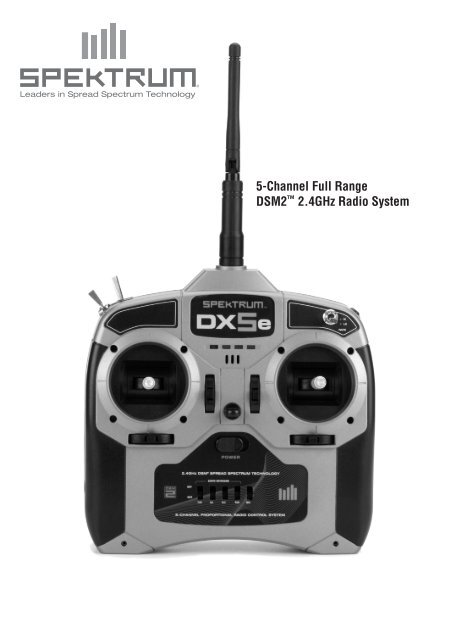
Leaders in Spread Spectrum Technology5-Channel Full RangeDSM2 2.4GHz Radio System
Table of ContentsSpektrum’s <strong>DX5e</strong> 5-channel DSM2Full Range System...................................... 2DSM2 DuaLink ® Technology............................ 4Receiver Compatibility...................................... 4Installing the Transmitter Batteries................... 5Charging Batteries............................................ 5Digital Trims..................................................... 6Low Battery Alarm............................................ 6Trainer.............................................................. 7Receiver Installation......................................... 7Binding............................................................. 8How to Range Test the <strong>DX5e</strong>............................ 9AR500 Failsafe................................................ 10HOW AR500 FAILSAFE WORKS..................... 10Servo Reversing............................................. 10Hi/Lo Rate....................................................... 10Elevon/ Delta mixing....................................... 11Receiver Power System Requirements........... 11Tips on Using 2.4GHz Systems...................... 12General Information........................................ 13Warranty Information..................................... 15Instructions for Disposal of WEEE by<strong>User</strong>s in the European Union.................... 17Optional Accessories...................................... 18Spektrum’s <strong>DX5e</strong> 5-channelDSM2 Full Range SystemSpektrum’s <strong>DX5e</strong> 5-channel system incorporates 2.4GHzDSM2 technology offering full beyond-the-limits-of-sightrange and is ideal for sport-sized electric, gas and glowpowered5-channel or fewer airplanes. No longer willyou have to wait for a frequency pin or be concerned thatsomeone may inadvertently turn on to your same frequency.With Spektrum DSM2 technology, when you’re ready to flysimply turn on, and go flying!Transmitter Control IdentificationRudder andElevator StickElevator TrimRudderTrimTrainer PortHI/LO Rate SwitchReversing SwitchesMode 1Mix SwitchAntennaTrainer SwitchChannel 5 SwitchThrottle andAileron StickThrottle TrimAileron TrimOn/Off SwitchCharge JackAntennaTrainer SwitchChannel 5 SwitchHI/LO Rate SwitchThrottle andRudder StickAileron andElevator StickThrottle TrimRudder TrimOn/Off SwitchElevator TrimAileron TrimTrainer PortCharge JackReversing SwitchesMode 2Mix Switch2 SPEKTRUM <strong>DX5e</strong> • RADIO USER’S GUIDE SPEKTRUM <strong>DX5e</strong> • RADIO USER’S GUIDE3
DSM2 DuaLink ® TechnologyYour <strong>DX5e</strong> transmits on the 2.4GHz band and utilizesDSM2 second-generation Digital Spread SpectrumModulation, giving beyond-visual range in all types andsizes of aircraft. Unlike conventional narrow band systems,Spektrum’s 2.4GHz digital DuaLink technology is virtuallyimmune to internal and external radio interference.Included with your <strong>DX5e</strong> is an AR500 5-channel fullrangesport receiver. The <strong>DX5e</strong> transmitter simultaneouslytransmits on two frequencies and the AR500 receivesboth frequencies, creating dual RF paths. This dual pathredundancy creates a bulletproof RF link. The AR500features two aileron outputs making it convenient whenusing airplanes with two aileron servos.Receiver CompatibilityThe <strong>DX5e</strong> is compatible with all current Spektrum and JR ®brands of DSM ® aircraft receivers. However, when using the<strong>DX5e</strong> with one of the Spektrum park flyer receivers, like theAR6000, AR6100, AR6100E, etc., it is imperative that thesereceivers be limited to flying Parkflyer-type aircraft.Park flyer ReceiversInstalling the TransmitterBatteriesThe <strong>DX5e</strong> requires 4 heavy duty or alkaline AA batteries.Battery InstallationCharging BatteriesIf using rechargeable batteries (optional), it is imperative thatyou fully charge the transmitter prior to each flying session.To do so, using the optional wall charger, leave the chargerand batteries connected overnight (16 hours).The optional charger (SPM9526) is designed to rechargeyour batteries at a rate of 150mA for the transmitter and150mA for the receiver battery pack. Do not use this chargerfor equipment other than Spektrum transmitters that use4-cell battery packs. The charging plug polarity may notbe the same and equipment damage can result. During thecharging operation, the charger’s temperature is slightlyelevated. This is normal.Charger Pigtail for Transmitter• AR6000• AR6100E• AR6100• AR6300Remove the battery door and install 4 AA batteries. Makesure the polarity of each corresponds with the diagram in thebattery holder. Replace the battery door.BLACK TO POSITIVEFull Range DSM2Aircraft ReceiversNote: Optional NiCd or NiMH 1.2-volt AA rechargeablebatteries can also be used. A charge jack is locatedon the right side of the transmitter for convenientrecharging. Spektrum offers optional replacement NiMHrechargeable batteries, part number SPM9525.BLACK W/WHITE STRIPE TO NEGATIVESpektrum Transmitter Charge Jack Polarity- +• AR6200 • AR7000 • AR9000A charging jack is located on the right side of the transmitter.If rechargeable batteries are used they can be convenientlycharged without removing them from the transmitter usingthe charge jack.• AR7100 • AR7100R • AR91004 SPEKTRUM <strong>DX5e</strong> • RADIO USER’S GUIDE SPEKTRUM <strong>DX5e</strong> • RADIO USER’S GUIDE5
IMPORTANT: All Spektrum charge jacks are center-pinnegative. This is the opposite of many chargers. Beforeusing a charger make sure the connector is center-pinnegative. This can be done using a voltmeter. Alsounlike conventional radio systems that use 8 cells topower the transmitter, the <strong>DX5e</strong> uses 4 cells. This is dueto the electronics being more efficient. When charging,be sure to use a charger designed for a 4-cell 4.8-voltbattery pack when charging the transmitter.Transmitter PolarityThe center pin on all Spektrum transmitters is negative.Therefore, the center pin on all Spektrum chargers isnegative, not positive. This is different from many othermanufacturers’ chargers and radio systems. Beware ofimproper connections based on “color coded” wire leads,as they may not apply in this instance. You must make surethat the center pin of your Spektrum transmitter is alwaysconnected to the negative voltage of your charger for correctpolarity hookup.Digital TrimsThe <strong>DX5e</strong> features digital trims. Each time a trimmer ismoved the servo output will change one step. If the trimmeris held, the output will scroll in that direction until thetrimmer is released or the output reaches its end.Throttle TrimRudder TrimElevator TrimAileron TrimMode 2TrainerThe <strong>DX5e</strong> offers a trainer function that allows the transmitterto operate as a master or slave. The trainer switch is locatedon the back left of the transmitter. When using the trainerfunction, plug the trainer cord (SPM6805) into the trainerport in both the master (controlling) and the slave (training)transmitters. The master transmitter must have the powerturned on and the slave transmitter must have the powerturned off.Note: The <strong>DX5e</strong> trainer system is compatible with allJR and Spektrum transmitters.MasterThe <strong>DX5e</strong> transmitter can be used as a master but the slavetransmitter must have the same programming (i.e. reverseswitch positions) as the master.SlaveWhen using the <strong>DX5e</strong> transmitter as a slave with another<strong>DX5e</strong>, it’s necessary to match all the reverse switchpositions.Receiver InstallationInstall the receiver using the same method you would useto install a conventional receiver in your aircraft. Typically,wrap the receiver in protective foam and fasten it in placeusing rubber bands or hook and loop straps. Alternately, inelectric models, it’s acceptable to use thick double-sidedfoam tape to fasten the main receiver in place.Mount the antennas such that the tip of the feeder (long)antenna is perpendicular (90 degrees) to the short antennaand the antennas are at least 2 inches apart. Essentially, eachantenna sees a different RF environment and this is key tomaintaining a solid RF link.Receiver InstallationElevator TrimRudder TrimThrottle TrimAileron TrimThe AR500 incorporates dual receiver antennas, offeringthe security of dual path RF redundancy. By locating theseantennas in slightly different locations in the aircraft, eachantenna is exposed to its own RF environment, greatlyimproving path diversity (the ability for the receiver tosee the signal in all conditions). The receiver features twoaileron outputs making it convenient when installing thereceiver in airplanes that have two aileron servos.Mode 1Low Battery AlarmWhen the battery voltage drops below 4.7 volts, an alarmwill sound and the voltage LEDs will flash.6 SPEKTRUM <strong>DX5e</strong> • RADIO USER’S GUIDE SPEKTRUM <strong>DX5e</strong> • RADIO USER’S GUIDE7
BindingThe AR500 receiver must be bound to the transmitterbefore it will operate. Binding is the process of teaching thereceiver the specific code of the transmitter so it will onlyconnect to that specific transmitter.Note: RTF and Radio Systems are pre-bound at thefactory. Rebinding is necessary if any settings arechanged to ensure proper failsafe settings are achieved.1. To bind an AR500 to a DSM2 transmitter, insert theBATT/BIND port in the charge plug receptacle.2. Power the receiver by plugging in a receiver batteryin any port on the receiver. Note that the LED onthe receiver should be flashing, indicating that thereceiver is in bind mode and ready to be bound to thetransmitter.4. Pull and hold the trainer switch on the top of thetransmitter while turning on the power switch. Releasethe trainer switch once the LEDs on the front of thetransmitter flash, and a series of tones are heard.Within a few seconds the system should connect.Once connected the LED on the receiver will go solidindicating the system is connected.Note: Continuing to hold the trainer switch during thebinding process will prevent preset failsafe positionsfrom being learned by the receiver.How to Range Test the <strong>DX5e</strong>Before each flying session, and especially with a newmodel, it is important to perform a range check. The <strong>DX5e</strong>incorporates a range testing system which, when placed inthe RANGE CHECK mode with the trainer switch activatedand held, reduces the output power, allowing a range check.Range Testing the <strong>DX5e</strong>1. With the model restrained on the ground, stand 30paces (approx. 90 feet/28 meters) away from the model.Note: Prior to performing the range check ensure thecorrect failsafe stick positions are established.Shown above using a separate receiver packNote: When binding using a switch harness andseparate receiver pack, a three-wire switch harnessmust be used such as SPM9530. (Not shown) You mayneed to purchase the Male/Female bind plug SPM6803in addition to the switch harness.2. Face the model with the transmitter in your normalflying position. Pull and hold the trainer switch whiletoggling the HI/LO Rate Switch four times. The LEDswill flash and the alarm will sound indicating the systemis in range check mode.Note: The trainer switch must be held the entire timeduring the range check process; releasing the trainerswitch will exit the range check mode.Trainer Switch5. Remove the bind plug from the BATT/BIND port on thereceiver before you power off the receiver and store it ina convenient place.6. After you’ve set up your model, it’s important to rebindthe system so the true low throttle and neutral controlsurface positions are programmed.HI/LO Rate SwitchNote: To bind an aircraft with an electronic speedcontroller that powers the receiver through the throttlechannel (ESC/BEC), insert the bind plug into the BATT/BIND port in the receiver and the throttle lead into thethrottle port. Proceed to Step #2.Shown above using an ESC/BEC and a flight pack3. Move the sticks and switches on the transmitter tothe desired AR500 failsafe positions (low throttle andneutral control positions).3. You should have total control of the model with thetrainer switch pulled at 30 paces (90 feet/28 meters).4. If control issues exist, call the Horizon ProductSupport Team at 1 877 504 0233 or go tohorizonhobby.com to find a local Spektrumdistributor for service in your country.30 paces (90 feet/28 meters)8 SPEKTRUM <strong>DX5e</strong> • RADIO USER’S GUIDE SPEKTRUM <strong>DX5e</strong> • RADIO USER’S GUIDE9
AR500 Failsafe• Prevents unintentional electric motor response onstart-up.• Eliminates the possibility of over-driving servos onstart-up.• Establishes low-throttle failsafe if the RF signal is lost.• The AR500 removes servo output pulses to all channelsexcept the throttle channel during failsafe.• The AR500 throttle failsafe position is stored via thethrottle stick position on the transmitter.How AR500 Failsafe WorksReceiver Power Only• In electric aircraft, when the receiver only is turned on(no transmitter signal is present), the throttle channelhas no output, to avoid operating or arming theelectronic speed control.• In glow-powered models, the throttle servo receives noinput so it remains in its current position.Note: Some analog servos will coast slightly eventhough there is no signal present. This is normal.• All other channels will move to the positions setduring bindingAfter Connection• When the transmitter is turned on, and after the receiverconnects to the transmitter, normal control of allchannels occurs.• After the system makes a connection, if loss of signaloccurs, the AR500 failsafe drives the throttle servo onlyto its preset failsafe position (low throttle) that was setduring binding.• All other channels receive no output pulses/ commands,and are not active during failsafe.Servo ReversingThe <strong>DX5e</strong> features servo reversing on channels 1-4. Theswitches are located at the lower front of the transmitterand are used to select the direction of each channel. Usea small screwdriver to change the switch position tonormal or reverse.Hi/Lo RateThe <strong>DX5e</strong> offers a high/low rate function on aileron,elevator and rudder. When the HI/LO rate switch is in theupper position or “HI” position, 100% travel is achievedon the aileron, elevator and rudder channels. When theswitch is in the lower position a reduced travel of 70% isachieved on the aileron, elevator and rudder channels. Thisis useful allowing the aircraft to have a high control rate(switch in the “HI” position) for aggressive maneuvers anda low control rate (switch in “LO” position) for smooth,precise maneuvers.• High 100% rate on aileron, elevator and rudder• Low 70% rate on aileron, elevator and rudderElevon/ Delta mixingThe <strong>DX5e</strong> offers an Elevon mix. Elevon (also called deltawing) mixing combines the function of ailerons with thefunction of the elevator to allow precise control of both rolland pitch for delta wing aircraft. To activate the Elevon mix,move the mix switch to the on (up) position.Elevon Wing Type ConnectionAILE Servo Port(Left Elevon)• ELEV servo port (right aileron)• AILE servo port (left aileron)ELEV Servo Port(Right Elevon)Note: If proper servo direction cannot be achievedwith the servo reversing switches, swap the servo inputleads from AILE to ELEV or vice versa.Receiver Power SystemRequirementsWith all radio installations, it is vital the onboard powersystem provides adequate power without interruption to thereceiver even when the system is fully loaded (servos atmaximum flight loads). This becomes especially critical withgiant-scale models that utilize multiple high-torque/ highcurrentservos. Inadequate power systems that are unableto provide the necessary minimum voltage to the receiverduring flight loads have become the number-one cause ofin-flight failures. Some of the power system componentsthat affect the ability to properly deliver adequate powerinclude: the selected receiver battery pack (number of cells,capacity, cell type, state of charge), switch harness, batteryleads, regulator (if used) and, unless it’s a regulator, powerbus (if used).While a Spektrum receiver’s minimum operational voltage is3.5 volts, it is highly recommended the systembe tested per the guidelines below to a minimum acceptablevoltage of 4.8 volts during ground testing. Thiswill provide head room to compensate for batterydischarging or if the actual flight loads are greater than theground test loads.Recommended Power System<strong>Guide</strong>lines1. When setting up large or complex aircraft with multiplehigh-torque servos, it’s highly recommended that acurrent and voltmeter (Hangar 9 HAN172) be used. Plugthe voltmeter in an open channel port in the receiverand, with the system on, load the control surfaces(apply pressure with your hand) while monitoring thevoltage at the receiver. The voltage should remain above4.8 volts even when all servos are heavily loaded.2. With the current meter in line with the receiver batterylead, load the control surfaces (apply pressurewith your hand) while monitoring the current. Themaximum continuous recommended current for asingle heavy-duty servo/battery lead is three ampswhile short-duration current spikes of up to five ampsare acceptable. Consequently, if your system drawsmore than three amps continuous or five amps for shortdurations, a single battery pack with a single switchharness plugged into the receiver for power will beinadequate. It will be necessary to use multiple packswith multiple switches and multiple leads plugged intothe receiver.10 SPEKTRUM <strong>DX5e</strong> • RADIO USER’S GUIDE SPEKTRUM <strong>DX5e</strong> • RADIO USER’S GUIDE11
3. If using a regulator, it’s important the above tests aredone for an extended period of 5 minutes. When currentpasses through a regulator, heat is generated. Thisheat causes the regulator to increase resistance, whichin turn causes even more heat to build up (thermalrunaway). While a regulator may provide adequatepower for a short duration, it’s important to test itsability over time as the regulator may not be able tomaintain voltage at significant power levels.4. For really large aircraft or complex models (for example35% and larger or jets), multiple battery packs withmultiple switch harnesses are necessary or in manycases one of the commercially available power boxes/busses is recommended. No matter what power systemsyou choose, always carry out test #1 above making surethat the receiver is constantly provided with 4.8 volts ormore under all conditions.5. The latest generation of Nickel-Metal Hydride batteriesincorporates a new chemistry mandated to be moreenvironmentally friendly. These batteries, when chargedwith peak detection fast chargers, have a tendency tofalse peak (not fully charge) repeatedly. These includeall brands of NiMH batteries. If using NiMH packs beespecially cautious when charging making absolutelysure that the battery is fully charged. It is recommendedto use a charger that can display total charge capacity.Note the number of mAh put into a discharged pack toverify it has been charged to full capacity.Tips on Using 2.4GHz SystemsYour DSM2 equipped 2.4GHz system is intuitive to operate,functioning nearly identically to FM systems. Following area few common questions from customers:1. Q: Which do I turn on first, the transmitter or thereceiver?A: It doesn’t matter, although it is suggested to turn thetransmitter on first. If the receiver is turned on first,the throttle channel doesn’t put out a pulse position atthis time, preventing the arming of electronic speedcontrollers, or in the case of an engine powered aircraft,the throttle servo remains in its current position. Whenthe transmitter is then turned on the transmitter scansthe 2.4GHz band and acquires two open channels. Thenthe receiver that was previously bound to the transmitterscans the band and finds the GUID (Globally UniqueIdentifier code) stored during binding. The system thenconnects and operates normally. If the transmitter isturned on first, the transmitter scans the 2.4GHz bandand acquires two open channels. When the receiveris turned on, the receiver scans the 2.4GHz bandlooking for the previously stored GUID. When it locatesthe specific GUID code and confirms uncorruptedrepeatable packet information, the system connects andnormal operation takes place. Typically this takes 2 to 6seconds.2. Q: Sometimes the system takes longer to connect andsometimes it doesn’t connect at all. Why?A In order for the system to connect (after the receiver isbound), the receiver must receive a large number ofcontinuous (one after the other) uninterrupted perfectpackets from the transmitter. This process is purposelycritical of the environment ensuring that it’s safe to flywhen the system does connect. If the transmitter is tooclose to the receiver (less that 4 feet) or if the transmitteris located near metal objects (metal transmitter case,the bed of a truck, the top of a metal work bench, etc.)connection will take longer. In some cases connectionwill not occur as the system is receiving reflected2.4GHz energy from itself and is interpreting thisas unfriendly noise. Moving the system away frommetal objects or moving the transmitter away from thereceiver and powering the system up again will causea connection to occur. This only happens during theinitial connection. Once connected the system is locked,and should a loss of signal occur (failsafe), the systemconnects immediately (4ms) when signal is regained.3. Q: I’ve heard that the DSM system is less tolerant of lowvoltage. Is this correct?A: All DSM receivers have an operational voltage range of3.5 to 9 volts. With most systems this is not a problemas in fact most servos cease to operate at around 3.8volts. When using multiple high-current draw servoswith a single or inadequate battery/ power source, heavymomentary loads can cause the voltage to dip belowthis 3.5-volt threshold causing the entire system (servosand receiver) to brown out. When the voltage dropsbelow the low voltage threshold (3.5 volts), the DSMreceiver must reboot (go through the start up process ofscanning the band and finding the transmitter) and thiscan take several seconds.4. Q: Sometimes my receiver loses its bind and won’tconnect, requiring rebinding. What happens if the bindis lost in flight?A: The receiver will never lose its bind unless it’s instructedto. It’s important to understand that during the bindingprocess the receiver not only learns the GUID (code) ofthe transmitter but the transmitter learns and stores thetype of receiver that it’s bound to. If the trainer switch ispulled on the transmitter at any time and the transmitteris turned on, the transmitter looks for the bindingprotocol signal from a receiver. If no signal is present,the transmitter no longer has the correct informationto connect to a specific receiver and in essence thetransmitter has been “unbound” from the receiver. We’vehad several customers using transmitter stands or traysthat unknowingly depress the bind button. The systemis then turned on, losing the necessary informationto allow the connection to take place. We’ve also hadcustomers that didn’t fully understand the range testprocess and pull the trainer switch before turning on thetransmitter, also causing the system to “lose its bind.”If the system fails to connect, one of the following hasoccurred:• The transmitter is near conductive material (transmittercase, truck bed, etc.) and the reflected 2.4GHz energy ispreventing the system from connecting. (See #2 above)• The trainer switch was pulled and the radio waspreviously turned on knowingly (or unknowingly),causing the transmitter to no longer recognize thereceiver.General InformationFCC InformationThis device complies with part 15 of the FCC rules.Operation is subject to the following two conditions: (1)This device may not cause harmful interference, and (2)this device must accept any interference received, includinginterference that may cause undesired operation.Caution: Changes or modifications not expresslyapproved by the party responsible for compliance couldvoid the user’s authority to operate the equipment.This product contains a radio transmitter with wirelesstechnology which has been tested and found to be compliantwith the applicable regulations governing a radio transmitterin the 2.400GHz to 2.4835GHz frequency range.Servo Precautions• Do not lubricate servo gears or motors.• Do not overload retract servos during retracted orextended conditions. Make sure they are able totravel their full deflection. Overloading or stalling aservo can cause excessive current drain.• Make sure all servos move freely through theirrotations and no linkages hang up or bind. A bindingcontrol linkage can cause a servo to draw excessivecurrent. A stalled servo can drain a battery pack in amatter of minutes.• Correct any control surface “buzz” or “flutter” as soonas it is noticed in flight, as this condition can destroythe feedback potentiometer in the servo. It may beextremely dangerous to ignore such “buzz” or “flutter.”• Use the supplied rubber grommets and brass servoeyelets when mounting your servos. Do not overtightenthe servo mounting screws, as this negates thedampening effect of the rubber grommets.• Ensure the servo horn is securely fastened to the servo.Use only the servo arm screws provided; the size isdifferent from other manufacturers.• Discontinue to use servo arms when they become“yellowed” or discolored. Such servo arms may bebrittle and can snap at any time, possibly causing theaircraft to crash.• Check all related mounting screws and linkagesfrequently. Aircraft often vibrate, causing linkages andscrews to loosen.12 SPEKTRUM <strong>DX5e</strong> • RADIO USER’S GUIDE SPEKTRUM <strong>DX5e</strong> • RADIO USER’S GUIDE13
General NotesRadio controlled models are a great source of pleasure.Unfortunately, they can also pose a potential hazard if notoperated and maintained properly.It is imperative to install your radio control system correctly.Additionally, your level of piloting competency must behigh enough to ensure that you are able to control youraircraft under all conditions. If you are a newcomer to radiocontrolled flying, please seek help from an experienced pilotor your local hobby store.Safety Do’s and Don’ts for Pilots• Ensure that your batteries have been properly chargedprior to your initial flight.• Keep track of the time the system is turned on so youwill know how long you can safely operate your system.• Perform a ground range check prior to the initial flightof the day. See the “Daily Flight Checks Section” forinformation.• Check all control surfaces prior to each takeoff.• Do not fly your model near spectators, parking areas orany other area that could result in injury to people ordamage of property.• Do not fly during adverse weather conditions. Poorvisibility can cause disorientation and loss ofcontrol of your aircraft. Strong winds can cause similarproblems.• Do not point the transmitter antenna directly toward themodel. The radiation pattern from the tip of the antennais inherently low.• Do not take chances. If at any time during flight youobserve any erratic or abnormal operation, landimmediately and do not resume flight until the cause ofthe problem has been ascertained and corrected. Safetycan never be taken lightly.Federal Aviation AdministrationPurposeThis advisory outlines safety standards for operations ofmodel aircraft. We encourage voluntary compliancewith these standards.BackgroundAttention has been drawn to the increase in model aircraftoperation. There is a need for added caution when operatingfree flight and radio controlled craft in order to avoidcreating a noise nuisance or a potential hazard to full-scaleaircraft and persons and/or property on the surface.Operating StandardsModelers generally are concerned with safety and exercisegood judgment when flying model aircraft. However, inthe interest of safer skies, we encourage operators ofradio controlled and free flight models to comply with thefollowing standards:a. Exercise vigilance in locating full-scale aircraft (get helpif possible) so as not to create a collision hazard.b. Select an operating site at sufficient distance frompopulated areas so you do not create a noise problem ora potential hazard.c. Do not fly higher than 400 feet above the surface.d. Always operate more than three miles from theboundary of an airport unless you are given permissionto be closer by the appropriate air traffic control facilityin the case of an airport for which a control zone hasbeen designated or by the airport manager in the case ofother airports.e. Do not hesitate to ask for assistance in complying withthese guidelines at the airport traffic control tower orair route traffic control center nearest the site of yourproposed operation.Information Provided ByDirector, Air Traffic Service Federal Aviation Administration,Washington, D.C.Daily Flight Checks1. Check the battery voltage on both the transmitter andthe receiver battery packs. Do not fly below 4.7V on thetransmitter or below 4.7V on the receiver. To do so cancrash your aircraft.Note: When you check these batteries, ensure thatyou have the polarities correct on your expanded scalevoltmeter.2. Check all hardware (linkages, screws, nuts, and bolts)prior to each day’s flight. Be sure that binding does notoccur and that all parts are properly secured.3. Ensure that all surfaces are moving in the propermanner.4. Perform a ground range check before each day’s flyingsession.5. Prior to starting your aircraft, turn off your transmitter,then turn it back on. Do this each time you start youraircraft. If any critical switches are on without yourknowledge, the transmitter alarm will warn you at thistime.6. Check that all trim levers are in the proper location.7. All servo pigtails and switch harness plugs shouldbe secured in the receiver. Make sure that the switchharness moves freely in both directions.Warranty InformationWarranty PeriodHorizon Hobby, Inc., (Horizon) warranties that the Productspurchased (the “Product”) will be free from defects inmaterials and workmanship at the date of purchase by thePurchaser.Limited Warranty(a) This warranty is limited to the original Purchaser(“Purchaser”) and is not transferable. REPAIR ORREPLACEMENT AS PROVIDED UNDER THIS WARRANTYIS THE EXCLUSIVE REMEDY OF THE PURCHASER. Thiswarranty covers only those Products purchased from anauthorized Horizon dealer. Third party transactions are notcovered by this warranty. Proof of purchase is requiredfor warranty claims. Further, Horizon reserves the right tochange or modify this warranty without notice and disclaimsall other warranties, express or implied.(b) Limitations- HORIZON MAKES NO WARRANTY ORREPRESENTATION, EXPRESS OR IMPLIED, ABOUTNON-INFRINGEMENT, MERCHANTABILITY OR FITNESSFOR A PARTICULAR PURPOSE OF THE PRODUCT. THEPURCHASER ACKNOWLEDGES THAT THEY ALONE HAVEDETERMINED THAT THE PRODUCT WILL SUITABLY MEETTHE REQUIREMENTS OF THE PURCHASER’S INTENDEDUSE.(c) Purchaser Remedy- Horizon’s sole obligation hereundershall be that Horizon will, at its option, (i) repair or (ii)replace, any Product determined by Horizon to be defective.In the event of a defect, these are the Purchaser’s exclusiveremedies. Horizon reserves the right to inspect any andall equipment involved in a warranty claim. Repair orreplacement decisions are at the sole discretion of Horizon.This warranty does not cover cosmetic damage or damagedue to acts of God, accident, misuse, abuse, negligence,commercial use, or modification of or to any part of theProduct. This warranty does not cover damage due toimproper installation, operation, maintenance, or attemptedrepair by anyone other than Horizon. Return of any goodsby Purchaser must be approved in writing by Horizon beforeshipment.14 SPEKTRUM <strong>DX5e</strong> • RADIO USER’S GUIDE SPEKTRUM <strong>DX5e</strong> • RADIO USER’S GUIDE15
Damage LimitsHORIZON SHALL NOT BE LIABLE FOR SPECIAL, INDIRECTOR CONSEQUENTIAL DAMAGES, LOSS OF PROFITSOR PRODUCTION OR COMMERCIAL LOSS IN ANYWAY CONNECTED WITH THE PRODUCT, WHETHERSUCH CLAIM IS BASED IN CONTRACT, WARRANTY,NEGLIGENCE, OR STRICT LIABILITY. Further, in no eventshall the liability of Horizon exceed the individual price ofthe Product on which liability is asserted. As Horizon hasno control over use, setup, final assembly, modificationor misuse, no liability shall be assumed nor accepted forany resulting damage or injury. By the act of use, setup orassembly, the user accepts all resulting liability.If you as the Purchaser or user are not prepared to acceptthe liability associated with the use of this Product, youare advised to return this Product immediately in new andunused condition to the place of purchase.Law: These Terms are governed by Illinois law (withoutregard to conflict of law principals).Safety PrecautionsThis is a sophisticated hobby Product and not a toy. Itmust be operated with caution and common sense andrequires some basic mechanical ability. Failure to operatethis Product in a safe and responsible manner could resultin injury or damage to the Product or other property. ThisProduct is not intended for use by children without directadult supervision. The Product manual contains instructionsfor safety, operation and maintenance. It is essential to readand follow all the instructions and warnings in the manual,prior to assembly, setup or use, in order to operate correctlyand avoid damage or injury.Questions, Assistance and RepairsYour local hobby store and/or place of purchase cannotprovide warranty support or repair. Once assembly, setupor use of the Product has been started, you must contactHorizon directly. This will enable Horizon to better answeryour questions and service you in the event that you mayneed any assistance. For questions or assistance, pleasedirect your email to productsupport@horizonhobby.com, orcall 877.504.0233 toll free to speak to a Product Support.Inspection or RepairsIf this Product needs to be inspected or repaired, pleasecall for a Return Merchandise Authorization (RMA). Packthe Product securely using a shipping carton. Please notethat original boxes may be included, but are not designedto withstand the rigors of shipping without additionalprotection. Ship via a carrier that provides tracking andinsurance for lost or damaged parcels, as Horizon is notresponsible for merchandise until it arrives andis accepted at our facility. A Service Repair Request isavailable at www.horizonhobby.com on the “Support” tab.If you do not have internet access, please include a letterwith your complete name, street address, email address andphone number where you can be reached during businessdays, your RMA number, a list of the included items, methodof payment for any non-warranty expenses and a briefsummary of the problem. Your original sales receipt mustalso be included for warranty consideration. Be sure yourname, address, and RMA number are clearly written on theoutside of the shipping carton.Warranty Inspection and RepairsTo receive warranty service, you must include youroriginal sales receipt verifying the proof-of-purchasedate. Provided warranty conditions have been met, yourProduct will be repaired or replaced free of charge. Repair orreplacement decisions are at the sole discretion of HorizonHobby.Non-Warranty RepairsShould your repair not be covered by warrantythe repair will be completed and payment willbe required without notification or estimate ofthe expense unless the expense exceeds 50% ofthe retail purchase cost. By submitting the item forrepair you are agreeing to payment of the repair withoutnotification. Repair estimates are available upon request.You must include this request with your repair. Non-warrantyrepair estimates will be billed a minimum of ½ hour oflabor. In addition you will be billed for return freight. Pleaseadvise us of your preferred method of payment. Horizonaccepts money orders and cashiers checks, as well as Visa,MasterCard, American Express, and Discover cards.United StatesElectronics and engines requiring inspection or repairshould be shipped to the following address:Horizon Service Center4105 Fieldstone RoadChampaign, Illinois 61822All other products requiring warranty inspection or repairshould be shipped to the following address:Horizon Support Team4105 Fieldstone RoadChampaign, Illinois 61822Please call 877.504.0233 or e-mail us at productsupport@horizonhobby.com with any questions or concerns regardingthis product or warranty.United KingdomElectronics and engines requiring inspection or repairshould be shipped to the following address:Horizon Hobby UKUnits 1-4 Ployters RdStaple TyeSouthern WayHarlowEssex CM18 7NSUnited KingdomPlease call +44 1279 641 097 or sales@horizonhobby.co.ukwith any questions or concerns regarding this product orwarranty.GermanyElectronics and engines requiring inspection or repairshould be shipped to the following address:Horizon Technischer ServiceOtto Hahn Str. 9a25337 ElmshornGermanyPlease call +49 4121 46199 66 or service@horizonhobby.de with any questions or concerns regarding this product orwarranty.USA: Please call 1 877 504 0233 or visithorizonhobby.com to find our distributor for yourcountry for support with any questions or concernsregarding this product or warranty.UK: Please call +44 1279 641 097 or sales@horizonhobby.co.uk with any questions or concernsregarding this product or warranty.Germany: Please call +49 4121 46199 66 orservice@horizonhobby.de with any questions orconcerns regarding this product or warranty.Instructions for Disposalof WEEE by <strong>User</strong>s in theEuropean UnionThis product must not be disposed of with other waste.Instead, it is the user’s responsibility to dispose of theirwaste equipment by handing it over to a designatedcollection point for the recycling of waste electrical andelectronic equipment. The separate collection and recyclingof your waste equipment at the time of disposal will help toconserve natural resources and ensure that it is recycled ina manner that protects human health and the environment.For more information about where you can drop off yourwaste equipment for recycling, please contact your local cityoffice, your household waste disposal service or where youpurchased the product.If you choose to pay by credit card, please include yourcredit card number and expiration date. Any repair leftunpaid or unclaimed after 90 days will be consideredabandoned and will be disposed of accordingly. Pleasenote: non-warranty repair is only available onelectronics and model engines.16 SPEKTRUM <strong>DX5e</strong> • RADIO USER’S GUIDE SPEKTRUM <strong>DX5e</strong> • RADIO USER’S GUIDE17
Optional AccessoriesBatteriesSPM9520................1100MAH 4.8V NICD RECEIVER PACKSPM9525................1500mAh Ni-MH AA 4PkSPMB1500NM........1500MAH 4.8V NIMH RECEIVER PACKSPMB1650NM........1650MAH 6.0V NIMH RECEIVER PACKSPMB2150NM........2150MAH 6.0V NIMH RECEIVER PACKSPMB2700NM........2700MAH 6.0V NIMH RECEIVER PACKSPMB4500NM........4500MAH 6.0V NIMH RECEIVER PACKChargersSPM9526................150mA Wall Chargerw/TX AdapterRemote Receiver ExtensionsSPM9010................REMOTE RECEIVEREXTENSION 6-inchSPM9011................REMOTE RECEIVEREXTENSION 9-inchSPM9012................REMOTE RECEIVEREXTENSION 12-inchSPM9013................REMOTE RECEIVEREXTENSION 24-inchSPM9014................REMOTE RECEIVEREXTENSION 36-inchServos & Servo AccessoriesSPMDSP.................DIGITAL SERVO PROGRAMMERSPMDSP60.............6.0G Super Sub-Micro DigitalProgrammable ServoSPMDSP60J............6.0G Super Sub-Micro DigitalProgrammable Servo JSTSPMDSP601...........GEAR SET DSP60SPMDSP602...........CASE SET DSP60SPMDSP603...........STD ARM SET W/SCREWS,FINE SPLINE DSP60SPMDSP604...........3D ARM SET W/SCREWS,FINE SPLINE DSP60SPMDSP75.............7.5GM Super Sub-MicroDigital Programmable ServoSPMDSP751...........GEAR SET DSP75SPMDSP752...........CASE SET DSP75SPMDSP753...........STD ARM SET W/SCRWS FINESPLINE DSP75SPMDSP754...........3D ARM SET W/SCREW FINESPLINE DSP75Voltage Regulators & AccessoriesSPMVR5203............VR5203 DUAL OUTPUT REGULATORSPMVR6010............VR6010 VOLTAGEREGULATOR 10A, 6VSPM6820................SOFT SWITCH: AR9100, VR6010SPM6821................CHARGEADAPT: VR6010, AR7100/RSPM6822................COOLING FAN: VR6010Switch HarnessesSPM9530................3 WIRE SWITCH HARNESSSPM9531................DUAL I/O 3 WIRE SWITCH HARNESS18 SPEKTRUM <strong>DX5e</strong> • RADIO USER’S GUIDE SPEKTRUM <strong>DX5e</strong> • RADIO USER’S GUIDE19
Leaders in Spread Spectrum TechnologyUS Address:4105 Fieldstone RoadChampaign, Illinois 61822(877) 504-0233UK Address:Horizon Hobby UKUnits 1–4 Ployters RdStaple TyeSouthern WayHarlowEssex CM18 7NSUnited Kingdom+44 1279 641 097www.horizonhobby.co.ukGerman Address:Horizon Deutschland GmbHOtto Hahn Strasse 9AElmshorn, Germany+49 4121 46199 60www.horizonhobby.de© 2008 Horizon Hobby, Inc.www.horizonhobby.comwww.spektrumrc.com© 2008 DSM and DSM2 are trademarks or registered trademarks of Horizon Hobby, Inc.The Spektrum trademark is used with permission of Bachmann Industries, Inc.Spektrum radios and accessories are exclusively available from Horizon Hobby, Inc.13118.2