7008/7108 Manual - Traxxas
7008/7108 Manual - Traxxas
7008/7108 Manual - Traxxas

Create successful ePaper yourself
Turn your PDF publications into a flip-book with our unique Google optimized e-Paper software.
BEFORE YOU PROCEEDCarefully read and follow all instructions in this and anyaccompanying materials to prevent serious damage to yourmodel. Failure to follow these instructions will be consideredabuse and/or neglect.Before running your model, look over this entire manual andexamine the model carefully. If for some reason you decide it is notwhat you wanted, then do not continue any further. Your hobbydealer absolutely cannot accept a model for return or exchangeafter it has been run.WARNINGS, HELPFUL HINTS, & CROSS-REFERENCESThroughout this manual, you’ll notice warnings and helpful hintsidentified by the icons below. Be sure to read them!An important warning about personal safety or avoidingdamage to your model and related components.Special advice from <strong>Traxxas</strong> to make things easierand more fun.Refers you to a page with a related topic.SUPPORTIf you have any questions about your model or its operation,call the <strong>Traxxas</strong> Technical Support line toll-free at:1-888-TRAXXAS (1-888-872-9927)*Technical support is available Monday through Friday from 8:30amto 9:00pm central time. Technical assistance is also available at<strong>Traxxas</strong>.com. You may also e-mail customer support with yourquestion at support@<strong>Traxxas</strong>.com. Join thousands of registeredmembers in our online community at <strong>Traxxas</strong>.com.<strong>Traxxas</strong> offers a full-service, on-site repair facility to handle anyof your <strong>Traxxas</strong> service needs. Maintenance and replacementparts may be purchased directly from <strong>Traxxas</strong> by phone or onlineat Buy<strong>Traxxas</strong>.com. You can save time, along with shippingand handling costs, by purchasing replacement parts from yourlocal dealer.Do not hesitate to contact us with any of your product support needs.We want you to be thoroughly satisfied with your new model!<strong>Traxxas</strong>1100 Klein RoadPlano, Texas 75074Phone: 972-265-8000Toll-free 1-888-TRAXXAS<strong>Traxxas</strong> U.K.P.O. Box 1128Winterbourne, BristolBS36-2SHEnglandPhone: 44-117-956-1002Internet<strong>Traxxas</strong>.comE-mail: support@<strong>Traxxas</strong>.comEntire contents ©2009 <strong>Traxxas</strong>.<strong>Traxxas</strong>, Ready-To-Race, Ready-To-Win, Titan, Velineon, 1/16Slash VXL 4WD, 1/16 E-Revo VXLand ProGraphix are trademarksor registered trademarks of<strong>Traxxas</strong>. Other brand names andmarks are the property of theirrespective holders and are usedonly for purposes of identification.No part of this manual may bereproduced or distributed in printor electronic media without theexpress written permission of<strong>Traxxas</strong>. Specifications are subjectto change without notice.*Toll-free support is available to U.S. residents only.TRAXXAS • 3
l = Myriad Semi BoldSAFETY PRECAUTIONSAll instructions andprecautions outlined in thismanual should be strictlyfollowed to ensure safeoperation of your model.3 3+ 4adhered to.5This model is not intendedfor use by children under14 years of age without thesupervision of a responsibleand knowledgeable adult.Previous experience withradio controlled modelsis recommended. Modelsrequire a higher level ofsetup, maintenance, orsupport equipment.4 • TRAXXASbluehighway fontFor Expert Drivers1All of us at <strong>Traxxas</strong> want you to safely enjoy your new model.Operate your model sensibly and with care, and it will be exciting,safe, and fun for you and those around you. Failure to operate yourmodel in a safe and responsible manner may result in propertydamage and serious injury. The precautions outlined in this manualshould be strictly followed to help ensure safe operation. You alonemust see that the instructions are followed and the precautions areIMPORTANT POINTS TO REMEMBERYour model is not intended for use on public roads or congestedareas where its operation can conflict with or disrupt pedestrianor vehicular traffic.Never, under any circumstances, operate the model in crowds ofpeople. Your model is very fast and could cause injury if allowedto collide with anyone.Because your model is controlled by radio, it is subject to radiointerference from many sources that are beyond your control.Since radio interference can cause momentary losses of radiocontrol, always allow a safety margin in all directions around themodel in order to prevent collisions.The motor, batteries, and speed control can become hot duringuse. Be careful to avoid getting burned.Don’t operate your model at night, or anytime your line of sightto the model may be obstructed or impaired in any way.Most importantly, use good common sense at all times.BATTERIES AND BATTERY CHARGINGYour model uses rechargeable batteries that must be handled withcare for safety and long battery life. Make sure to read and follow allinstructions and precautions that were provided with the batterypack and your charger. It is your responsibility to charge and carefor the battery backs properly. In addition to your battery andcharger instructions, here are some more tips to keep in mind.Use the supplied charger to charge the includedbattery. See “Use The Right Charger” on page 11.Never leave batteries to charge unattended.Remove the battery from the model while charging.Always unplug the battery from the electronic speed controlwhen the model is not in use and when it is being storedor transported.Allow the battery pack to cool off between runs(before charging).Do not use battery packs that have been damaged in any way.Do not use battery packs that have damaged wiring, exposedwiring, or a damaged connector.Children should have responsible adult supervision whencharging and handling batteries.SPEED CONTROLBELOW TEXT HAS BEEN UPDATED on 3-14-07Kent wants maintenance text to be at the ENDDisconnect the Battery: Always disconnect the battery from thespeed control when not in use.Transmitter on First: Switch on your transmitter first beforeswitching on the speed control to prevent runaways anderratic performance.Don’t Get Burned: The heat sink can get extremely hot, so beChoose the Model That is Right For You.careful not to touch it until it is cool. Supply adequate airflowfor cooling.No previous experience with radio controlled models is required.Use Stock Connectors: If you decide to change the batteryModels require a minimum of setup, maintenance, or support equipment.or motor connectors, only change one battery or motor connectorat a time. This will prevent damage from accidentally mis-wiringPrevious the speed experience control. Please with radio note controlled that modified models speed is recommended.controls canModels be subject require to a a rewiring higher level fee when of setup, returned maintenance, for service. or support Removing equipment.the battery connector on the speed control or using connectorsPrevious with no reverse-polarity experience with radio protection controlled the models speed is control mandatory. will These voidmodels the product’s are capable warranty. of high speeds, requiring experienced driving control.Models require detailed setup, and/or maintenance procedures with requiredInsulate the Wires: Always insulate exposed or damaged wiringsupport equipment.with heat shrink tubing to prevent short circuits.Previous No Reverse experience Voltage: with The radio speed controlled is models not protected is mandatory. againstThese models are capable of very high speeds and require an even higherreverse polarity voltage. When changing the battery and/orlevel of skilled driving control. Models require detailed setup, and/or maintenanceprocedures with required support equipment.motor, be sure to install the same type of connectors to avoidreverse polarity damage to the speed control. Removing theFor Expert Drivers Only. This product is capable of extreme speedbattery connectors on the speed control or using the same-genderand acceleration! It carries our highest skill level rating and is intendedconnectors on the speed control will void the product’s warranty.for expert drivers only. Experience with nitro-powered radio controlledNo Schottky Diodes: External Schottky diodes are not compatiblemodels is required!with reversing speed controls. Using a Schottky diode will damagethe electronic speed control and void the 30-day warranty.NMMPcdePccrFafm
TOOLS, SUPPLIES AND REQUIRED EQUIPMENTYour model comes with a set of specialty metric tools. You’ll need to purchase other items, available from your hobby dealer, to operateand maintain your model.SUPPLIED TOOLS AND EQUIPMENTREQUIRED EQUIPMENT(sold separately)For more information onbatteries, see Use the RightBatteries on page 10.1.5mm “L” wrench 2.0mm “T” wrench2.5mm ball driver wrench 4-way wrench6-cell 2/3A NiMH batteryNiMH battery chargerBody clipsDECORATING YOUR MODEL8 AA alkalinebatteriesRecommended EquipmentThese items are not requiredfor the operation of yourmodel, but are a good idea toinclude in any R/C toolbox:• Safety glasses• Thin, hobby-qualitycyanoacrylate instant tireglue (CA glue)• Hobby knife• Side cutters and/or needlenose pliers• Philips screwdriver• Soldering ironAPPLYING THE DECALSThe main decals for your modelhave been applied at the factory.The decals are printed on selfadhesiveclear mylar and are diecutfor easy removal. Use a hobbyknife to lift the corner of a decaland lift it from the backing. Toapply the decals, place one enddown, hold the other end up, andgradually smooth the decal downwith your finger as you go. Thiswill prevent air bubbles. Placingboth ends of the decal down andthen trying to smooth it out willresult in air pockets.Look at the photos on the box fortypical decal placement.TIRE GLUINGThe factory tires on your model are already glued to the rims. Thetires must be glued to the rims to prevent the rims from spinning insidethe tires. The instructions here are provided to show you how to gluereplacement tires to the rims in the future. Use CA tire glue availablefrom your local hobby dealer. You can glue the tires without removingthe wheels from the truck. For clarity, these instructions show the processwith the wheels removed.1. Remove a wheel from the model usingthe larger (7mm) end of the universalwrench.2. Use your thumb to push the side of thetire away from the rim. Place one or twodrops of CA glue into the opening andrelease the tire. Capillary action will drawthe glue around the bead of the tire.3. Repeat step two at four or five points around the rim, until the tireis completely secured to the rim. Turn the rim over and repeat theprocess for the inside of the rim/tire. Repeat for the other three wheels.4. Reinstall the wheels, make sure none of the axle pins have fallen outfrom behind the hex hubs.9TRAXXAS • 5
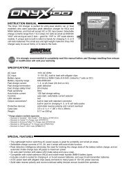
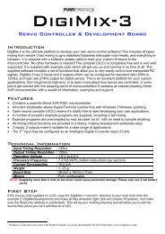
ANATOMY OF THE 1/16 SLASH VXL 4WDRear Half ShaftTurnbuckleRear BodyMountRearBumperBattery Compartment VentBattery Door Release TabAntenna MountBattery Compartment DoorReceiver BoxSlipper ClutchHex HubPivot BallAxle CarrierTurnbucklePush RodRockerFrontBumperFront BodyMountRockerPush RodRear SuspensionArm<strong>Traxxas</strong> High-CurrentConnector6 • TRAXXASElectronic SpeedControl (VXL-3m)Motor (Velineon ® 380)TransmissionSteering ServoChassisOil Shock(Damper)FrontSuspension ArmSpring PreloadAdjuster
QUICK START: GETTING UP TO SPEEDThe Quick Start Guide isnot intended to replace thefull operating instructionsavailable in this manual.Please read this entiremanual for completeinstructions on the properuse and maintenance ofyour model.The following guide is an overview of the procedures for getting your model running. Look for the Quick Start logo on the bottomcorners of Quick Start pages.1. Read the safety precautions on page 4 9. Detail your model • See page 5For your own safety, understand where carelessness and misuse Apply other decals if desired.could lead to personal injury.2. Charge the battery pack • See sidebar, page 11 10. Drive your model • See page 18Fully charge the battery pack included with your model.Driving tips and adjustments for your model.3. Install the antenna • See page 12 11. Maintaining your model • See page 26Install the antenna mast in the model.Follow these critical steps to maintain the performanceof your model and keep it in excellent running condition.4. Install batteries in the transmitter • See page 12The transmitter requires 8 AA alkaline or rechargeable batteries.5. Install the battery pack • See page 13Install the included battery pack in your model.6. Turn on the radio system • See page 15Make a habit of turning the transmitter on first, and off last.Look for the Quick Startlogo at the bottom ofQuick Start pages.8 • TRAXXAS7. Check servo operation • See page 15Make sure the steering servo is working correctly.8. Range test the radio system • See page 15Follow this procedure to make sure your radio system works properlyat a distance and that there is no interference from outside sources.
THE TRAXXAS TQ RADIO SYSTEMUse the Right BatteriesYour transmitter uses AAbatteries. Use new alkalinebatteries, or rechargeablebatteries such as NiCad orNiMH (Nickel Metal Hydride)batteries in your transmitter.Make sure rechargeablebatteries are fullycharged according to themanufacturer’s instructions.If you use rechargeablebatteries in yourtransmitter, be awarethat when they beginto lose their charge, they losepower more quickly thanregular alkaline batteries.Caution: Discontinue runningyour model at the first sign ofweak batteries (flashing redlight) to avoid losing control.10 • TR A X X ASRADIO SYSTEM TERMINOLOGYPlease take a moment to familiarize yourself with these radio andpower system terms. They will be used throughout this manual.BEC (Battery Eliminator Circuit) - The BEC can either be in thereceiver or in the ESC. This circuit allows the receiver and servosto be powered by the main battery pack in an electric model.This eliminates the need to carry a separate pack of 4 AAbatteries to power the radio equipment.Brushless Motor - A D/C brushless motor replaces the brushedmotor’s traditional commutator and brush arrangement withintelligent electronics that energize the electromagneticwindings in sequence to provide rotation. Opposite of a brushedmotor, the brushless motor has its windings (coils) on theperimeter of the motor can and the magnets are mounted to thespinning rotor shaft.Channel - The 27 MHz frequency band is divided into 6 channelsso that up to six models can be operated simultaneously. Eachchannel is referred to by its flag color and channel number, asshown below.Channel FrequencyBandFlagColor<strong>Traxxas</strong>Part No.1 26.995 Brown 20312 27.045 Red 20323 27.095 Orange 20334 27.145 Yellow 20345 27.195 Green 20356 27.255 Blue 2036Clearing your frequency - A routine, verbal check to make surenobody else in your area is operating on the same channel.Always clear your frequency by calling out your channel numberbefore operating your model. Wait or move to another area ifyour channel is already being used.Cogging - Cogging is a condition sometimes associated withbrushless motors. Typically it is a slight stutter noticed whenaccelerating from a stop. It happens for a very short period asthe signals from the electronic speed control and the motorsynch with each other. The VXL-3m is optimized to virtuallyeliminate cogging.Crystal (X-tal) - The plug-in device that determines which channelthe radio system will operate on. For each channel, there aretwo crystals, one for the receiver and one for the transmitter. Ofthose two crystals, the one marked with the lower number (.455MHz lower) must be inserted into the receiver.Current - Current is a measure of power flow through theelectronics, usually measured in amps. If you look at wire like agarden hose, current is a measure of how much water is flowingthrough the hose.ESC (Electronic Speed Control) - An electronic speed control isthe electronic motor control inside the model. Electronic speedcontrols use power more efficiently than mechanical speedcontrols so that the battery runs longer. An electronic speedcontrol also has circuitry that prevents loss of steering andthrottle control as the battery loses its charge.Frequency band - The radio frequency used by the transmitter tosend signals to your model. All <strong>Traxxas</strong> RTR models operate on a27 MHz frequency band.kV Rating - Brushless motors are often rated by their kV number.The kV rating equals no-load motor rpm with 1 volt applied.The kV increases as the number of wire turns in the motordecreases. As the kV increases, the current draw through theelectronics also increases.LiPo - Abbreviation for Lithium Polymer. Rechargeable LiPobattery packs are known for their special chemistry that allowsextremely high energy density and current handling in acompact size. These are high performance batteries that requirespecial care and handling. For advanced users only.mAh – Abbreviation for milliamp hour. A measure of the capacityof the battery pack. The higher the number, the longer thebattery will last between recharges.Neutral position - The standing position that the servos seekwhen the transmitter controls are at the neutral setting.
THE TRAXXAS TQ RADIO SYSTEMNiCad - Abbreviation for nickel-cadmium. The originalrechargeable hobby pack, NiCad batteries have very high currenthandling, high capacity, and can last up to 1000 charging cycles.Good charging procedures are required to reduce the possibilityof developing a “memory” effect and shortened run times.NiMH - Abbreviation for nickel-metal hydride. RechargeableNiMH batteries offer high current handling, and much greaterresistance to the “memory” effect. NiMH batteries generallyallow higher capacity than NiCad batteries. They can last up to500 charge cycles. A peak charger designed for NiMH batteries isrequired for optimal performance.Receiver - The radio unit inside your model that receives signalsfrom the transmitter and relays them to the servos.Resistance - In an electrical sense, resistance is a measure of howan object resists or obstructs the flow of current through it.When flow is constricted, energy is converted to heat and islost. <strong>Traxxas</strong> power systems are optimized to reduce electricalresistance and the resulting power-robbing heat.Rotor - The rotor is the main shaft of the brushless motor.In a brushless motor, the magnets are mounted to therotor, and the electromagnetic windings are built into themotor housing.Sensored - Sensored refers to a type of brushless motor thatuses an internal sensor in the motor to communicate rotorposition information back to the electronic speed control.Sensorless - Sensorless refers to a brushless motor that usesadvanced instructions from an electronic speed control toprovide smooth operation. Additional motor sensors and wiringare not required.Servo - Small motor unit in your model that operates thesteering mechanism.Transmitter - The hand-held radio unit that sends throttle andsteering instructions to your model.Trim - The fine-tuning adjustment of the neutral position of theservos, made by adjusting the throttle and steering trim sliderson the face of the transmitter.Thermal Shutdown Protection - Temperature sensing electronicsused in the electronic speed control detect overloading andoverheating of the transistor circuitry. If excessive temperature isdetected, the unit automatically shuts down to prevent damageto the electronics.2-channel radio system - The TQ radio system, consisting ofthe receiver, the transmitter, and the servos. The system uses twochannels: one to operate the throttle and one to operatethe steering.Voltage - Voltage is a measure of the electrical potentialdifference between two points, such as between the positivebattery terminal and ground. Using the analogy of the gardenhose, while current is the quantity of water flow in the hose,voltage corresponds to the pressure that is forcing the waterthrough the hose.Use the Right ChargerYour model includes a ‘wallcharger’ that will chargethe supplied battery inapproximately six hours.Unplug the battery fromthe charger, and unplug thecharger from the wall, whencharging is complete.For faster charging, the<strong>Traxxas</strong> TRX Power Charger(item #3030X) may be used incombination with a <strong>Traxxas</strong>High Current Plug adapter(item #3062). This will reducecharging time to about onehour. The Power Charger willdetect when the battery packis fully charged, and stopcharging automatically.Certain aftermarket chargersmay also be used to chargethe included battery, butuse caution when selectinga charger. ‘Timer’ ormechanical chargers witha clockwork timer are notrecommended as they mayovercharge the battery. Wesuggest you ask your localhobby dealer to help youselect an appropriate charger,or call 1-888-TRAXXAS so ourcustomer support team canhelp you.No matter which charger youchoose, never leave a batteryunattended while charging.Always follow the chargermanufacturer’s instructions.2TRAXXAS • 11
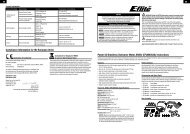
THE TRAXXAS TQ RADIO SYSTEMIf the power indicatordoesn’t light red, check thepolarity of the batteries.Check rechargeablebatteries for a full charge.Spray a little window cleaneron the antenna wire to makeit easier to push through theantenna tube.INSTALLING TRANSMITTER BATTERIESYour TQ transmitter uses 8 AA batteries (see sidebar, page 10).The battery compartment is located in the base of the transmitter.SETTING UP THE ANTENNA1. Locate the black antenna wire thatexits the receiver box.2. Pull the wire straight with your fingersand then insert the end of the wireinto one end of the antenna tube (theantenna tube can be found in thedocuments bag). Push the wire all theway through the antenna tube. Thewire is longer than the tube. Do notcut or shorten the antenna wire.3. Insert the base of the tube into theantenna mount. Take care not to crimpthe antenna wire.AntennaTipIf there are any kinks in theblack antenna wire, it willbe more difficult to pushthrough the antenna tube.Pull the wire straight bysandwiching it between yourthumb and index finger andrunning your fingers alongthe length of the wire (withmedium pressure).Don’t shorten the length ofthe antenna wire. Its lengthis tuned to the frequencyband; cutting it couldseverely shorten the radiosystem’s range.1. Remove the battery compartment door by pressing the tab andlifting the door up.2. Install the batteries in the correct orientation as indicated in thebattery compartment.3. Reinstall the battery door and snap it closed.4. Turn on the transmitter and check the power indicator for a solidred light.If the power indicator light flashes, then the transmitter batteriesare weak, discharged or possibly installed incorrectly. Replace withnew or freshly charged batteries. The power indicator light does notindicate the charge level of the battery pack installed in the model.4. Using the supplied 1.5mm “L” wrench,thread the 1.5mm set screw into theopening next to the antenna. Tightenthe set screw until it is flush with thetop of the opening.5. Fold the top of the antenna wire overthe top of the antenna tube. Slidethe antenna tip onto the top of theantenna tube. Do not cut or shortenthe antenna wire.6. The receiver antenna installation iscomplete. Always fully extend thetransmitter’s telescoping antennawhen running your model. Make ahabit of holding the transmitter so theantenna points straight up.AntennaTube1.5mmWrenchSetScrewAntennaMountSee page 20 for moreinformation about thereceiver box and maintaininga watertight seal.12 • TR A X X AS3, 4
THE TRAXXAS TQ RADIO SYSTEMINSTALLING THE BATTERY PACKYour model includes a 7.2-volt battery pack. To properly balance themodel, it should be installed in the battery compartment on the left sideof the model. Follow these steps to install the battery:Battery Installation1. Open the batterycompartment door bypressing on the release tabs.2. Install the battery pack withthe battery wires facing therear of the model.Battery Wire Slot3. Route the battery wire throughthe slot near the vent.4. Close the battery door,making sure not to pinch thebattery wires. Be sure bothBattery Orientationrelease tabs are fully engagedwith the door. Do not connect the battery pack to the ESC at this time.Note: always unplug the battery and remove from the model after use.Using LiPo Packs in Your ModelThe VXL-3m is compatible with 2S and 3S LiPo packs, and is equippedwith Low Voltage detection circuitry to prevent over-discharging. Makecertain LiPo mode is selected (see page 17 for details) when using LiPopacks in your model.Using an Additional Battery for Increased Run Time<strong>Traxxas</strong> 1/16 models only require one battery pack, but the chassis canaccept two batteries. Your model can be run with two battery packs toextend run time. The batteries must be connected in parallel, which willcombine the capacity of the two batteries (for example, two 7.2-volt1000mAh packs connected in parallel will deliver a total capacity of2000mAh, but total voltage will remain 7.2 volts). This is easily done witha parallel Y-harness (Part #3064, sold separately). Be sure to only use theY-harness with identical battery packs; do not mix batteries of differentchemistries or capacities.When operating your model with two batteries, be carefulto monitor the temperature of the speed control and motorto prevent overheating. Stop running your model and allowit to cool if the speed control’s thermal overload protectionactivates or if the motor temperature exceeds 200° F.Using an Additional Battery For Increased SpeedAn additional battery may also be used to increase the top speed ofyour model, by connecting the batteries in series using a <strong>Traxxas</strong> seriesconnector (Part #3063, sold separately). This also requires a gearing changeusing the supplied, optional pinion gear as described on page 23.Precautions• The High Speed dual-battery battery and gearingconfiguration is for high-speed running on smoothsurfaces only. Avoid repetitive hard acceleration to preventoverstressing the motor, speed control and batteries.• Failure to install the appropriate gearing can cause failureof the motor, speed control and batteries when running themodel on 12 NiMH cells. See the gearing chart on page 23 formore information about properly gearing your model.• Make certain both batteries are fully charged beforeinstalling them in your model. Installing a fully charged packand a partially discharged pack may lead to overdischargingand damage to the partially discharged battery.• Do not mix batteries of different brands, chemistries orcapacities. Only genuine <strong>Traxxas</strong> batteries are approved fordual-battery use in this model.• Stop running your model and allow it to cool if the speedcontrol’s thermal overload protection activates or if themotor temperature exceeds 200° F.THE TRAXXAS HIGH CURRENT CONNECTORYour model is equipped with the <strong>Traxxas</strong> High-Current Connector. Standard connectors restrictcurrent flow and are not capable of delivering thepower needed to maximize the output of your model.The <strong>Traxxas</strong> connector’s gold-plated terminals with alarge contact surfaces ensure positive current flow with the least amount ofresistance. Secure, long-lasting, and easy to grip, the <strong>Traxxas</strong> connector isengineered to extract all the power your battery has to give.To run this model, your batteries must be equipped with <strong>Traxxas</strong> High-Current Connectors. Batteries can either be purchased new with <strong>Traxxas</strong>connectors installed or <strong>Traxxas</strong> connectors can be purchased to install onbattery packs you already own. See sidebar for packages available fromyour hobby dealer.The typical Molex ® style connector is inadequate for use inyour model. It creates resistance that becomes a bottleneck tocurrent flow. If your battery pack is equipped with a Molexconnector, it must be replaced with a <strong>Traxxas</strong> High-CurrentConnector to mate with the electronic speed control.MolexconnectorThe following <strong>Traxxas</strong> HighCurrent Connector packagesare available from yourhobby dealer. When usingadapters, be careful not toexceed the current rating ofthe Molex connector.Part #3060Single Male/FemalePart #3061Male Charge AdapterPart #3062Female Charge AdapterPart #30802-Pack FemalePart #30702-Pack MaleFor best off-road handlingwith two battery packs,consider installing stiffersprings on your model.<strong>Traxxas</strong> offers accessorysprings for this purpose; seethe parts list included withyour model for part numbers.5TRAXXAS • 13
THE TRAXXAS TQ RADIO SYSTEMDon’t push the transmitterantenna down from thetop. Pull it down from thebottom, one segment at atime, to prevent binding andkinking the antenna mast.TQ RADIO SYSTEM CONTROLSTURN LEFTTURN RIGHTBrake/ReverseNeutralAccelerateElectronic Throttle TrimThe electronic throttle trim located on the face of the transmitteradjusts the neutral (center) point of the electronic speed control.This control has been preset for you at the factory.Electronic Steering TrimThe electronic steering trim located on the face of the transmitteradjusts the neutral (center) point of the steering servo whenthe servo is at rest. Adjust this control to make the model drivestraight with no steering input at the wheel.Servo Reversing SwitchesThe servo reversing switches are located on the front of thetransmitter, next to the on/off switch. Moving a switch reversesthe direction of the corresponding servo.Each switch corresponds to a channel, as shown below. Forexample, if you turn the steering wheel to the right and yourwheels turn left, you would move the Channel 1 switch tocorrect the servo direction. It may be necessary to adjust thecorresponding trim control after moving a switch.14 • TR A X X ASTQ RADIO SYSTEM ADJUSTMENTSIn addition to the electronic throttle and steering trim controls,your radio system features throttle neutral adjustment and servoreversing switches. These are preset at the factory and shouldnot require further adjustment.Throttle Neutral AdjustmentThe throttle neutral adjustment is located on the transmitter faceand controls the forward/reverse travel of the throttle trigger.Change the adjustment by pressing the button and sliding it tothe desired position.There are two settings available:50/50: Allows equal travel for bothacceleration and reverse.70/30: Allows more throttle travel (70%)and less reverse travel (30%).Note: If you change throttle travel, youwill need to reprogram the electronicspeed control.Channel12Default SettingServoSteeringThrottle
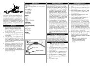
THE TRAXXAS TQ RADIO SYSTEMTQ RADIO SYSTEM RULESEach time you prepare to run your model, youmust clear your frequency to be sure no oneelse in the area is using the same channel asyou. There are six possible channels, numbered1 through 6. Each is represented by a color.Look at the crystal plugged into the back ofyour transmitter to determine which channelyour model is assigned to.Always turn your TQ transmitter on first and offlast. This procedure will help to prevent yourmodel from receiving stray signals from another transmitter,or other source, and running out of control.Always have the transmitter turned on before plugging inthe battery.Channel 1BrownChannel 2RedChannel 3OrangeChannel 4YellowChannel 5GreenChannel 6BlueAlways use new or freshly charged batteries for the radiosystem. Weak batteries will limit the range of the radio signalbetween the receiver and the transmitter. Loss of the radiosignal can cause you to lose control of your model.1 2Always turn yourtransmitter on first.Plug in the battery.Turn on the model.see TQ Radio System Setup, step 4.TQ RADIO SYSTEM SETUPThe TQ Radio System was pre-adjusted at the factory. Theadjustment should be checked, before running the model,in case of movement during shipping. Here’s how:1. Fully extend the chrome antenna mast on the transmitter andturn the switch on. The red indicator light on the transmittershould be solid red (not flashing).2. Elevate the model so that all four tires are off the ground.If you are holding the model, make sure hands and clothing areclear of the wheels and other moving parts on the model.3. Plug the battery pack in the model into the speed control.34. The on/off switch is integrated into the speed control. Withthe transmitter on, press the ESC set button for ½ second, untilthe LED shines GREEN, then immediately release the button.This turns the model on (see page 16 for more on ESC setup andoperation). To turn the ESC off, press the set button until thegreen LED turns off. Always disconnect your battery when themodel is not in use.5. Turn the steering wheel on the transmitter back and forth andcheck for rapid operation of the steering servos. Also, check thatthe steering mechanism is not loose or binding. If the steeringoperates slowly, check for weak batteries.6. When looking down at model, thefront wheels should be pointingstraight ahead. If the wheels areturned slightly to the left or right,slowly adjust the steering trimcontrol on the transmitter untilthey are pointing straight ahead.7. Gently apply the throttle -1 ° trigger to ensure that -1 ° you have fullforward and reverse operation, and that the motor stops whenthe throttle trigger is at neutral.8. Once adjustments are made, turn off your model, followed bythe hand held transmitter.RANGE-TESTING THE TQ RADIO SYSTEMBefore each running session with your model, you should rangetestyour radio system to ensure that it operates properly.1. Turn on the radio system and check its operation as describedin the previous section.2. Have a friend hold the model securely. Make sure handsand clothing are clear of the wheels and other moving partson the model.3. Make sure your transmitter antenna is fully extended, and thenwalk away from the model with the transmitter until you reachthe farthest distance you plan to operate the model.4. Operate the controls on the transmitter once again to be surethat the model responds correctly.5. Do not attempt to operate the model if there is any problemwith the radio system or any external interference with yourradio signal at your location.0 ° 0 ° section on page 16.Remember, always turn theTQ transmitter on first andoff last to avoid damage toyour model.Your speed control wasadjusted to the radio fromthe factory. It is possiblefor the throttle trim controlon the transmitter to havemoved during transit0°0°or while handling thetransmitter. If the LED blinksfast green when the ESC isturned on, this means eitherthe transmitter is turnedoff, or the throttle trimhas moved from its preset-1.5 ° position. -1.5 °If anything morethan a slight adjustment ofthe throttle trim control isrequired, then you shouldreadjust your speed control.Refer to the adjustmentsWhen rechargeable batteriesbegin to lose their charge,they will fade much fasterthan alkaline dry cells. Stopimmediately at the first signof weak batteries. Never turnthe transmitter off when thebattery pack is pluggedin. The model could run outof control.6, 7, 8TRAXXAS • 15
ADJUSTING THE ELECTRONIC SPEED CONTROLVXL-3m LED codesSolid Green: VXL-3m power onlight. Low Voltage Detection isON (LiPo setting).Solid Red: VXL-3m power on light.Low Voltage Detection is OFF(NiCad/NiMH setting).Fast Blinking Red: Thermal ShutdownProtection Stage 1. If the motor haslower than normal power and the VXL-3mis hot, the VXL-3m has entered Stage 1Thermal Shutdown Protection to guardagainst overheating caused by excessivecurrent flow. If the motor has no powerand the VXL-3m is very hot, the VXL-3mhas entered Stage 2 Thermal ShutdownProtection and has automatically shutdown. Let the VXL-3m cool. Make sureyour model is properly geared for theconditions (see page 23).Slow Blinking Red (with Low VoltageDetection on): The VXL-3m has enteredLow Voltage Protection. When thebattery voltage begins to reach theminimum recommended dischargevoltage threshold for LiPo battery packs,the VXL-3m will limit the power outputto 50% throttle. When the batteryvoltage attempts to fall below theminimum threshold, the VXL-3m willshut down all motor output. The LED onthe speed control will slowly blink red,indicating a low voltage shutdown. TheVXL-3m will stay in this mode until a fullycharged battery is connected.Alternating; Blinks Red then Green: Ifthe motor has no power, the VXL-3mhas entered Over Voltage Protection.If a battery with too high voltage isused, the VXL-3m will go into a failsafemode. Warning: If input voltage exceedsapproximately 20 volts, the ESC may bedamaged. Maximum peak input voltagelimits are 12.6V in LiPo Mode (see page17) and 18V in NiMH Mode.Blinking Green: The VXL-3m is indicatingthe transmitter Throttle Trim (see page14) is incorrectly set. Adjust the ThrottleTrim to the middle “0” setting.16 • TR A X X ASThe electronic speed control is factory set and should not require anyadjustments. These instructions are provided for your reference.Transmitter Adjustments for the electronic speed controlBefore attempting to program your ESC, it is important to makesure your TQ transmitter is properly adjusted (set back to the factorydefaults). Otherwise, you may not get the best performance from yourspeed control.The transmitter should be adjusted as follows:1. Set the throttle neutral switch to the 50/50 setting. This adjuststhe transmitter’s throttle trigger throw to 50% for throttle and50% for braking and reverse.2. Set the throttle trim control to the middle “0” setting.3. Set the Channel 2 servo reversing switch to the left position. Donot change the position of any of the servo reversing switchesafter programming the ESC.4. You are now ready to program your speed control.Setup Programming (Calibrating your ESC and transmitter)Read through all of the following programming steps before youbegin. If you get lost during programming or receive unexpectedresults, simply unplug the battery, wait a few seconds, plug the batteryback in, and start over.1. Disconnect each of the motor wires between the ESC and themotor. This is a precaution to prevent runaway when the speedcontrol is turned on before it is programmed.2. Connect a fully charged battery pack to the ESC.A3. Turn on the transmitter (with the throttle at neutral).4. Press and hold the EZ-Set button (A). The LEDGreen then Redwill first turn green and then red. Release theEZ-Set button.B5. When the LED blinks RED ONCE.Pull the throttle trigger to thefull throttle position and hold it Once Redthere (B).C6. When the LED blinks RED TWICE.Push the throttle trigger to thefull reverse and hold it there (C). Twice Red7. When the LED starts flashing GREEN,programming is complete. After the throttle isreturned to neutral, the LED will then shine solidgreen or red (depending on the low-voltagedetection setting, see note below) indicating theVXL-3m is on and at neutral (D).SolidESC OperationNote: In steps 1-7 below, Low Voltage Detection is turned off (factorydefault) and the LED shines RED. If Low Voltage Detection is on, theLED will shine GREEN instead of RED in steps 1-7 below.To operate the speed control and test the programming, place thevehicle on a stable block or stand so all of the driven wheels are off theground. Reconnect the motor wires. Always make sure that objects andfingers are clear of the wheels.1. With the transmitter on, press the EZ-Set button for ½ second,until the LED shines GREEN, then immediately release the button.This turns on the ESC. If you press and release too quickly, youmay hear the steering servos jump but the LED may not stay on.2. Apply forward throttle. The LED will turn off until full throttlepower is reached. At full throttle, the led will shine RED.3. Move the trigger forward to apply the brakes. Note that brakingcontrol is fully proportional. The LED will turn off until fullbraking power is reached. At full brakes, the LED will shine RED.4. Return the throttle trigger to neutral. The LED will shine RED.5. Move the throttle trigger forward again to engage reverse(Profile #1). The LED will turn off. Once full reverse power isreached, the LED will shine RED.6. To stop, return the throttle trigger to neutral.7. To turn the ESC off, press the EZ-Set button until the RED LEDturns off.VXL-3m Thermal Shutdown ProtectionThe VXL-3m is also equipped with thermal shutdown protection. If theoperating temperature exceeds safe limits, the ESC will reduce powerto 50% and the LED will flash red. Additional heating will cause thespeed control to shut down completely until it reaches a safe operatingtemperature. <strong>Traxxas</strong> encourages you to stop driving as soon as thethermal overload protection is activated.D
ADJUSTING THE ELECTRONIC SPEED CONTROLESC Profile SelectionThe speed control is factory set to Profile #1. To change the profile,follow the steps on described on the next page. The speed controlshould be connected to the receiver and battery, and the transmittershould be adjusted as described previously. The profiles are selectedby entering the programming mode.ESC Profile DescriptionProfile #1 (Sport Mode): 100% Forward, 100% Brakes, 100% ReverseProfile #2 (Race Mode): 100% Forward, 100% Brakes, No ReverseProfile #3 (Training Mode): 50% Forward, 100% Brakes, 50% ReverseSelecting Sport Mode (Profile #1)1. Connect a fully charged batterypack to the ESC and turn onyour transmitter.Green to Red to Off2. With the ESC off, press and holdthe EZ-Set button until the lightturns solid green, then solid redand then begins blinking red(indicating the Profile numbers).Release3. When the light blinks red once, release the EZ-Set button.4. The light will then turn red and the model is ready to drive.One blink RedSolid RedSelecting Race Mode (Profile #2)1. Connect a fully charged batterypack to the ESC and turn onyour transmitter.Green to Red to Off2. With the ESC off, press and holdthe EZ-Set button until the lightturns solid green, then solid redand then begins blinking red(indicating the Profile numbers).Release3. When the light blinks red twice, release the EZ-Set button.4. The light will then turn red and the model is ready to drive.Two blinks RedSolid RedSelecting Training Mode* (Profile #3)1. Connect a fully charged batterypack to the ESCand turn on your transmitter.2. With the ESC off, press and holdthe EZ-Set button until the lightturns solid green, then solid redand then begins blinking red(indicating the Profile numbers).Green to Red to OffReleaseThree blinks RedSolid Red3. When the light blinks red three times, release the EZ-Set button.4. The light will then turn red and the model is ready to drive.Note: If you missed the mode you wanted, keep the EZ-Set buttonpressed down and the blink cycle will repeat until a Mode is selected.LiPo Battery Mode with Low Voltage DetectionThe VXL-3m ESC is equipped with built-in Low Voltage Detectionfor safe use with Lithium Polymer (LiPo) batteries. The Low VoltageDetection circuitry constantly monitors the battery voltage. When thebattery voltage begins to reach the minimum recommended dischargevoltage threshold for LiPo battery packs, the VXL-3m will limit thepower output to 50% throttle. When the battery voltage attempts to fallbelow the minimum threshold, the VXL-3m will shut down all motoroutput. The LED on the speed control will slowly blink red, indicating alow voltage shutdown. The VXL-3m will stay in this mode until a fullycharged battery is connected. The electronic speed control is factoryset with Low Voltage Detection turned off. Be certain to activate LowVoltage Detection if you install LiPo batteries in your model.To turn Low Voltage Detection on (LiPo setting):1. Make sure the LED on the ESC is on and red.2. Press and hold the EZ-Set button for ten seconds. The LED willturn off and then light green. Also, a “rising” musical tone will beemitted from the motor.3. Low Voltage Detection is now ON.To turn Low Voltage Detection off (NiMH setting):1. Make sure the LED on the ESC is on and green.2. Press and hold the EZ-Set button for ten seconds. The LED willturn off and then light red. Also, a “falling” musical tone will beemitted from the motor.3. Low Voltage Detection is now OFF.Never use LiPo batteries while Low Voltage Detection is turned off.*Patent-pendingPatent Pending TrainingMode (Profile #3) reducesforward and reverse throttleby 50%. Training Modeis provided to reduce thepower output allowingbeginning drivers to bettercontrol the model. As drivingskills improve, simply changeto Sport or Race Mode forfull-power operation.Tip For Fast Mode ChangesThe ESC is set to Profile 1(Sport Mode) as the default.To quickly change to Profile 3(Training Mode), with thetransmitter on and the ESCturned off, press and holdthe SET button until the lightblinks red three times and thenrelease. For full power, turn offthe ESC then quickly changeback to Profile 1 (SportMode) by pressing andholding the SET button untilthe light blinks red one timeand then releasing.TRAXXAS • 17
DRIVING YOUR MODEL18 • TR A X X AS10Now it’s time to have some fun! This section contains instructions ondriving and making adjustments to your model. Before you go on, hereare some important precautions to keep in mind.Allow the model to cool for a few minutes between runs. This isparticularly important when using high capacity battery packs thatallow extended periods of running. Monitoring temperatures willextend the lives of the battery and motor.Do not continue to operate the model with low batteries or youcould lose control of it. Indications of low battery power includeslow operation and sluggish servos (slow to return to center). Stopimmediately at the first sign of weak batteries. When the batteries inthe transmitter become weak, the red power light will begin to flash.Stop immediately and install new batteries.Do not drive the model at night, on public streets, or in large crowds of people.If the model becomes stuck against an object, do not continue to runthe motor. Remove the obstruction before continuing. Do not push orpull objects with the model.Because the model is controlled by radio, it is subject to radiointerference from many sources beyond your control. Since radiointerference can cause momentary losses of control, allow a safetymargin of space in all directions around the model in order toprevent collisions.Use good, common sense whenever you are driving your model.Intentionally driving in an abusive and rough manner will only resultin poor performance and broken parts. Take care of your model sothat you can enjoy it for a long time to come.High performance vehicles produce small vibrations which mayloosen hardware over time. Frequently check wheel nuts and otherscrews on your vehicle to ensure that all hardware remains properlytightened.About Run TimeA large factor affecting run time is the type and condition of yourbatteries. The milliamp hour (mAh) rating of the batteries determineshow large their “fuel tank” is. A 2000 mAh battery pack will theoreticallyrun twice as long as a 1000 mAh pack. Because of the wide variation inthe types of batteries that are available and the methods with which theycan be charged, it’s impossible to give exact run times for the model.Another major factor which affects run time is how the model is driven.Run times may decrease when the model is driven repetitively from astop to top-speed and with repetitive hard acceleration.Tips for Increasing Run TimeUse batteries with the highest mAh rating you can purchase.Use the included charger or a high-quality peak-detecting charger.Read and follow all maintenance and care instructions provided bythe manufacturer of your batteries and charger.Keep the ESC cool. Get plenty of airflow across the ESC heat sinks.Lower your gear ratio. Installing smaller pinion gears will lower yourgear ratio and cause less power draw from the motor and batteries,and reduce overall operating temperatures.Maintain your model. Do not allow dirt or damaged parts to causebinding in the drivetrain. Keep the motor clean.mAh Ratings and Power OutputThe mAh rating of the battery can effect your top speed performance.The higher capacity battery packs experience less voltage drop underheavy load than low mAh rated packs. The higher voltage potential allowsincreased speed until the battery begins to become dischargedRUNNING IN WET CONDITIONSThe 1/16 Slash VXL 4WD and 1/16 E-Revo VXL are designed with waterresistantfeatures to protect the electronics in the model (receiver,servos, electronic speed control). This gives you the freedom to havefun driving your model through puddles, wet grass, snow, and otherwet conditions. Though highly water resistant, the model should not betreated as though it is submersible or totally, 100% waterproof. Waterresistance applies only to the installed electronic components. Runningin wet conditions requires additional care and maintenance for themechanical and electrical components to prevent corrosion of metalparts and maintain their proper function.PrecautionsWithout proper care, some parts of your model can be seriouslydamaged due to contact with water. Know that additionalmaintenance procedures will be required after running in wetconditions in order to maintain the performance of your model. Donot run your model in wet conditions if you are not willing to acceptthe additional care and maintenance responsibilities.
DRIVING YOUR MODELNot all batteries can be used in wet environments. Consult yourbattery manufacturer to see if their batteries can be used inwet conditions.The <strong>Traxxas</strong> TQ transmitter is not water resistant. Do not subject it towet conditions such as rain.Do NOT operate your model during a rain storm or other inclementweather where lightning may be present.Do NOT allow your model to come in contact with salt water (oceanwater), brackish water (between fresh water and ocean water), orother contaminated water. Salt water is highly conductive and highlycorrosive. Use caution if you plan to run your model on or near a beach.Even casual water contact can reduce the life of your motor. Specialcare must be taken to modify your gearing and/or your driving stylein wet conditions to extend the life of the motor (details below).Before Running Your Vehicle in Wet Conditions1. Consult the section “After Running Your Vehicle in Wet Conditions”before proceeding. Make sure you understand the additionalmaintenance required with wet running.2. The wheels have small holes molded in to allow air to enter and exitthe tire during normal running. Water will enter these holes and gettrapped inside the tires if holes are not cut in the tires. Cut two smallholes (4mm or 3/16” diameter) in each tire. Each hole should be nearthe tire centerline, 180 degrees apart.3. Confirm that the receiver box O-ring and cover are installed correctlyand secure. Make sure the screws are tight and the blue O-ring is notvisible protruding from the edge of the cover.4. Confirm that your batteries can be used in wet conditions.5. Use lower gearing (smaller pinion gears) when running in mud, deeppuddles, snow, or other similar situations that will restrict the tiresand put much higher loads on the motor.Motor PrecautionsMotor life can be greatly reduced in mud and water. If the motorget excessively wet or submerged, use very light throttle (run themotor slowly) until the excess water can run out. Applying fullthrottle to a motor full of water can cause rapid motor failure. Yourdriving habits will determine motor life with wet motor. Do notsubmerge the motor under water.Do not gear the motor by temperature when running in wetconditions. The motor will be cooled by water contact and will notgive an accurate indication of appropriate gearing.After Running Your Vehicle in Wet Conditions1. Drain the tires by spinning the tires at full throttle to “sling” the waterout. An easy way to do this is to remove the body and set the truckupside down on a flat surface. Apply full throttle so the tires spin andthrow the excess water out of the holes you cut into the tires.2. Remove the battery.3. Rinse excess dirt and mud off the truck with low-pressure water, suchas from a garden hose. Do NOT use pressure washer or other highpressurewater. Avoid directing water into the bearings, transmission,differentials, etc.4. Blow off the truck with compressed air (optional, but recommended).Wear safety glasses when using compressed air.5. Remove the wheels from the truck6. Spray all the bearings, drivetrain, and fasteners with WD-40 ® or similarwater displacing light oil7. Let the truck stand or you may blow off with compressed air. Placingthe truck in a warm sunny spot will aid drying. Trapped water and oilwill continue to drip from the truck for a few hours. Place it on a towelor piece of cardboard to protect the surface underneath.8. As a precautionary step, remove the sealed receiver box cover. Whileunlikely, humidity or tiny amounts of moisture or condensation mayenter the receiver box during wet running. This can cause long-termproblems with the sensitive electronics in the receiver. Removingthe receiver box cover during storage allows the air inside to dry. Thisstep can improve the long-term reliability of the receiver. It is notnecessary to remove the receiver or unplug any of the wires.9. Additional Maintenance: Increase your frequency of disassembly,inspection and lubrication of the following items: This is necessaryafter extended wet use or if the vehicle will not be used for anextended period of time (such as a week or longer). This additionalmaintenance is needed to prevent any trapped moisture fromcorroding internal steel components.• Stub axle housing bearings: Remove, clean, and re-oil the bearings.• Front and rear differential: Remove, disassemble, clean, and regreasethe differentials. Refer to your exploded view diagrams forhelp with disassembly and reassembly.TRAXXAS • 19
DRIVING YOUR MODEL• Transmission: Remove, disassemble,and clean the transmissioncomponents. No grease is requiredfor the nylon gears. Refer to yourexploded view diagrams for help withdisassembly and reassembly.• Motor: Remove the motor, cleanwith aerosol motor cleaner, and re-oilthe bushings (Titan 380 motor) orbearings (Velineon 380 motor) with lightweight motor oil. Be sureto wear eye protection when using spray aerosol cleaners.RECEIVER BOX: MAINTAINING A WATERTIGHT SEALRemoving and Installing Radio GearThe unique design of the receiver box allows the removal andinstallation of the receiver without losing the ability to maintain awatertight seal in the box. The patent-pending wire clamp featuregives you the ability to also install aftermarket radio systems andmaintain the watertight features of the receiver box.Removing the Receiver1. Remove the 2.5x8mm screws that secure the wire clamp.2. Remove the 2.5x8mm screws that secure the receiver box lid to thechassis. Lift the lid up and toward you to disengage the lid’s tab fromits slot in the chassis.3. You can now access the receiver. Unplug the servo cables from thereceiver and remove the receiver.AReceiver Installation1. Route the antenna wireout of the receiver boxcover (A). Place the coveron the chassis.2. Route the servo andspeed control leads into the receiver box cover.Use the molded-in wire guides to align theservo and speed control leads and antennawire (B).3. Apply a small bead of silicone grease (<strong>Traxxas</strong>part #1647) to the wire clamp (C).4. Install the wire clamp and tighten the two2.5x8mm screws securely (D).BCD5. Lift the receiver box cover and plugthe servo and speed control leads intothe receiver (E). Refer to page 9 for thewiring diagram.6. Bundle the wires so they fit beneath thereceiver box cover. You may secure thereceiver to the chassis with mounting tapeif you wish, but this is not required. Theexcess wire beneath the cover will preventthe receiver from rattling.7. Make sure the blue O-ring is properlyseated into the groove around the receivercover base so the cover will not pinch ordamage the O-ring. Snap the receiver boxcover into place (F).8. Inspect the cover to make sure the O-ringis not visible. If it is, remove the cover andreposition the O-ring. With the O-ring andcover properly seated, install the 2.5x8mmscrews and tighten them securely (G).EFG20 • TR A X X AS
TUNING ADJUSTMENTSThe Slash VXL 4WD and E-Revo VXL are factory-tuned for optimumperformance in a wide variety of off-road conditions. To tailor theperformance and handling of your model to suit your driving style andterrain, both models have a number of adjustable features. Gearing,shock preload and damping, ride height and wheel camber can all beeasily adjusted.SUSPENSION TUNINGRide Height AdjustmentThe Slash VXL 4WD andE-Revo VXL both havethreaded shock bodiesthat make it easy to adjustride height. Threading theshocks’ preload collarsCompression 2/3away from the caps willRide Heightraise the vehicle’s rideSag (Droop) 1/3height (the distanceAxle Centerline at Max CompressionAxle Centerline at Ride Heightfrom the chassis to theAxle Centerline at Max Sagground), and reduce thesuspension’s down travel,also known as ‘sag’ or‘droop’. This can be helpful in rugged terrain where extra groundclearance is needed. However, the vehicle’s center of gravity (CG) willbe raised, making it less stable.Threading the shocks’ preload collars toward the caps will lower thevehicle’s ride height and increase the suspension’s droop. This willlower the vehicle’s CG and improve handling, but it will also reduceground clearance.From the factory, Slash VXL 4WD and E-Revo VXL are set up as shownin the illustration above. At rest, the suspension sags to about 1/3of its total travel. This allows the suspension to extend so the wheelcan drop into depressions over rough terrain. This leaves 2/3 of thetotal suspension travel for compression when absorbing bumps andlanding jumps. These settings are ideal for most surfaces, and onlysmall changes in ride height should be required to fine-tune thevehicle’s handling for your particular surface.Total TravelShock OilThe 4 oil-filled shocks (dampers) effectively control the suspensionmovement by preventing the wheels and tires from continuingto “bounce” after rebounding from a bump. Changing the oil inthe shocks can vary the suspension damping effect. Changing theoil to a higher viscosity oil will increase damping. Lowering theviscosity of the oil will cause the suspension damping to be reduced.Damping should be increased (with higher viscosity oil) if the modelis bottoming easily over jumps. Damping should be decreased (withthinner viscosity oil) if the model is hopping over small bumps andfeels unstable. The viscosity of shock oil is affected by extremesin operating temperature; an oil of certain viscosity will becomeless viscous at higher temperatures and more viscous at lowertemperatures. Operating in regions with cold temperatures mayrequire lower viscosity oil. The Slash VXL 4WD’s shocks are filled withSAE 30W oil. The E-Revo VXL’s shocks are filled with SAE 40W oil. Onlyuse 100% silicone oil in the shock.Replacing Shock OilThe shocks have to be removed from the vehicle and disassembled tochange the oil.1. Remove the lower springretainer and shock spring.2. Remove the upper shockcap. If you cannot unscrewthe cap with your fingers,pass the 2mm ‘L’ wrenchthrough the cap’s eyeletso you can apply moreleverage. Turn the cap counterclockwise to loosen it.3. Empty the used shock oil from the shock body.4. Fill the shock with new silicone shock oil up to the top of theshock body.5. Slowly move the piston up and down (always keeping it submergedin oil) to release the air bubbles. Let the shock sit for a few minutesto allow any remaining air bubbles to surface.6. Slowly thread the upper cap with the installed shock bladder ontothe shock body. The excess oil will bleed out of the small hole in theshock cap.7. Tighten the shock cap until snug.Important: The shocks areassembled at the factory witha center-to-center distance(between the rod end balls)of 47.75mm. Any time theshocks are removed anddisassembled, this distanceshould be checked to ensureproper operation of thesuspension.47.75mmTRAXXAS • 21
TUNING ADJUSTMENTSA camber gauge (availableat your local hobby shop)can be a useful tool foralignment setting.To achieve a good startingpoint for the slipper clutch,tighten the slipper clutchadjusting nut clockwise untilthe slipper clutch adjustingspring fully collapses (do notover tighten), and then turnthe slipper clutch nut counterclockwise¾ to 1 turn.22 • TR A X X ASStatic Camber AdjustmentThe wheels can be set to have eitherpositive or negative camber (seeillustration below). The camber anglechanges as the wheel moves up anddown through its range of travel. Staticcamber is the camber angle at the wheelwhen the vehicle is set at its normal,stationary ride height.The suspension pivot balls located in the axle carriers adjust the staticcamber. Camber is factory-set at negative 1-degree, with the pivot ballsthreaded all the way into the suspension arms. To adjust static camber,insert the supplied 2mm hex wrench into the pivot ball (compressingthe suspension until the arms are parallel to the ground will allow foreasier hex wrench engagement). Negative camber can be increased byunthreading the lower pivot ball. Zero camber or positive camber (notrecommended) can be achieved by unthreading the upper pivot ball.Note that camber changes will also effect the toe angle of the wheelbeing adjusted.Static Camber Base Factory SettingsFront: 1-degree negative camber each sideRear: 1-degree negative camber each sidePositive camberZero camberNegative camberTRANSMISSION TUNINGAdjusting the Slipper ClutchSlash VXL 4WD and E-Revo VXLare equipped with an adjustableTorque Control slipper clutch whichis built into the large spur gear.The purpose of the slipper clutchis to prevent over-stressing of thedrivetrain and transmission gears. It may also be used to regulate theamount of power sent to the rear wheels to prevent tire spin. When itslips, the slipper clutch makes a high-pitch, whining noise.To adjust the slipper clutch, remove the receiver box cover.The slipper clutch is integrated into the main spur gear on thetransmission. The slipper clutch is adjusted using the spring-loadedlocknut on the slipper shaft. Use the supplied universal wrench.To tighten or loosen the slipper nut, insert the 1.5mm hex wrenchinto the hole in the end of the slipper shaft. This locks the shaft foradjustments. Turn the adjustment nut clockwise to tighten (lessslippage) and counter-clockwise to loosen (more slippage)Tuning The Sealed Gear DifferentialsThe Slash VXL 4WD and E-Revo VXL’s front and rear gear differentialsallow the left and right wheels to spin at different speeds while turningso that the tires do not scuff or skid. This decreases the turning radiusand increases steering performance.The performance of the differentials can be tuned for different drivingconditions and performance requirements. The differentials are filledwith silicone differential fluid, and are sealed to maintain consistentlong-term performance. Changing the oil in the differential with eitherlower or higher viscosity oil will vary the performance characteristicsof the differentials. Changing to a higher viscosity oil in the differentialwill reduce the tendency for power to be transferred to the wheel withthe least traction. You may notice this when making sharp turns on slicksurfaces. The unloaded wheels on the inside of the turn have the leasttraction and tend to spin up to extremely high rpms. Higher viscosity(thicker) oil causes the differential to act like a limited-slip differential,distributing more equal power to the left and right wheels. Your model
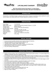
TUNING ADJUSTMENTSwill generally benefit from higher viscosity oil when climbing, rockcrawling, or racing on low traction surfaces. Note: Heavier oil will allowpower to be transferred even with one or more tires off the ground.This can make the vehicle more likely to overturn.From the factory, both the differentials are filled with SAE 30,000Wviscosity silicone oil. Only use silicone oil in the differentials. <strong>Traxxas</strong>sells SAE 10,000W and SAE 50,000W viscosity oil (see your parts list).The differentials have to be removed from the vehicle and disassembledto change/replace oil.MOTOR AND GEARINGExtensive testing has been done to determine the best gear ratiosfor the Slash VXL 4WD and E-Revo VXL models. The stock gearingbalances power, speed, and efficiency to optimize the performanceof the models. However, you may wish to try different gear ratiosin order to customize the performance of your model. The gearingchart on this page shows appropriate gearing for both models.By installing a pinion with fewer teeth, or a spur gear with moreteeth, the transmission’s final drive ratio is increased. This meansgreater rpm is required to achieve a given speed. Using a numericallyhigher gear ratio will increase torque, but reduce top speed.Installing a pinion with more teeth, or a spur gear with fewer teeth,will decrease the final drive ratio, which will generally increase topspeed but reduce torque. However, installing too large a pinion will“overgear” the car, which will reduce performance and may overheatthe motor and speed control. Use the following formula to calculatethe overall ratio for combinations not listed on the gear chart:# Spur Gear Teeth x 5.04 = Final Gear Ratio# Pinion Gear TeethGearing for 50+mphThe included “High Speed” pinion gear will allow your model toreach 50+mph when used with an additional Power Cell Series 1battery (Part #2925) and (Part #3063) series connector (battery andseries connector sold separately).Pinion GearSpur Gear45 50 5511 - - 25.2012 - - 23.1013 - - 21.3214 - - 19.8015 - - 18.4816 - 15.75 17.3317 - 14.82 16.3118 - 14.00 15.4019 - 13.26 14.5920 - 12.60 13.8621 10.80 12.00 13.2022 10.31 11.45 12.6023 9.86 10.96 12.0524 9.45 10.50 11.5525 9.07 10.08 11.0926 8.72 9.69 10.6627 8.40 9.33 10.2728 8.10 9.00 9.9029 7.82 8.69 9.5630 7.56 8.40 9.2431 7.32 8.13 8.9432 7.09 7.88 -33 6.87 7.64 -Gearing Compatibility ChartThe chart on the left shows a fullrange of gear combinations. Thestock ratio for E-Revo VXL is shown inblue. The stock ratio for Slash VXL isshown in red.The gear combinations in gray arenot suitable for either model whenusing the included 6-cell battery,speed control and motor. These gearcombinations have been included inthis chart as they may be used withcertain other aftermarket equipmentcombinations.Stock <strong>7108</strong> E-Revo VXLStock <strong>7008</strong> Slash VXL 4WDAcceptable range <strong>7008</strong> & <strong>7108</strong>Acceptable range <strong>7008</strong> only50+mph <strong>7108</strong> E-Revo VXL50+mph <strong>7008</strong> Slash VXL 4WDNot suitable for stock models50+mph Pinion Installation Instructions1. Remove the motor as described on page 24.2. Use the supplied 1.5mm wrench to loosen the pinion’s set screw.Remove the stock pinion.TRAXXAS • 23
TUNING ADJUSTMENTS24 • TR A X X AS3. Place the high speed pinion gear ontothe motor shaft. Align the set screw holewith the flat side of the shaft.4. Thread the supplied 1.5mm set screwinto the high speed pinion gear but donot tighten it yet.5. Slide the pinion gear down the motorshaft so the wrench shaft fits into thenotch in the motor mount, as shown.Tighten the set screw.To complete the installation, reinstall the motor and set the gearmesh as described to the right. Make certain the pinion does notcontact the motor mount or motor plate.50+mph Battery Installation Instructions1. Install the supplied battery as described on page 13.2. Install an identical Power Cell Series 1 battery (#2925) soldseparately) in the opposite battery compartment.3. Plug both batteries into the Y-harness (sold separately). The harnessconnects the two packs in series. The two 7.2-volt 6-cell batterypacks will operate as one 14.4-volt 12-cell battery pack.4. Plug the Y-harness into the speed control.Precautions• Make certain both batteries are fully charged beforeinstalling them in your model. Installing a fully charged packand a partially discharged pack may lead to overdischargingand damage to the partially discharged battery.• Do not mix batteries of different brands, chemistries orcapacities. Only genuine <strong>Traxxas</strong> batteries are approved fordual-battery use in this model.• The high speed dual-battery and gearing configurationis for high-speed running on smooth surfaces only. Avoidrepetitive hard acceleration to prevent overstressing themotor, speed control and batteries. Stop running yourmodel and allow it to cool if the speed control’s thermaloverload protection activates or if the motor temperatureexceeds 200° F. Failure to install the appropriate gearing cancause failure of the motor, speed control and batteries whenrunning the model on 12 NiMH cells.Motor InstallationTo access the motor,remove the gearcover by removingthe single screw onthe top of the gearcover. The motoruses an aluminummount for quick,easy motor access and gearing adjustment. Motor Mount PositionsTo remove the motor, first open the rightbattery door and slide out the ESC. Next,remove the single large hex screw usingthe supplied 2.5mm wrench. Then rotatethe motor and mount to the side of themodel, and slide backward off the post.The motor mount was carefullyengineered to provide additionalBrushed Motorsfeatures and adjustability. Two sets ofBrushless Motorsholes are provided for use with brushedand brushless motors. The holes for brushed motors are spaced16mm apart and accept 2.5mm screws. The holes for brushlessmotors are spaced 19mm apart and accept 3mm screws.Adjusting Gear MeshIncorrect gear mesh is the most commoncause of stripped spur gears. Gear meshshould be checked and adjusted anytime agear is replaced. Access the gears by removingthe single screw on the top gear cover.To set the gear mesh, cut a narrow strip ofnotebook paper and run it into the gear meshof the motor. The motor is mounted to analuminum motor mount. Loosen the singlemotor mount screw with the provided 2.5mmwrench to slide the motor mount. Slide themotor and pinion gear into the spur gear.Retighten the motor mount screw and thenremove the strip of paper. You should be ableto run a fresh strip of paper through the gearswithout binding them.Motor MountScrewDo Not Loosen
WHEELS AND TIRESThe Slash VXL 4WD and E-Revo VXL use 12mm axle hexes whichallow many types of aftermarket tires and wheels to be adaptedfor use on your model. Most will affect the overall width and thesuspension geometry of the model. The offsets and dimensionsdesigned into the model’s wheels are intentional; therefore,<strong>Traxxas</strong> cannot recommend the use of other non-<strong>Traxxas</strong> wheelswith different specifications. Experimentation with different typesof tires is recommended to see which ones work the best on theterrain where the model is run. Soft compound tires with manyshort spikes generally work better on hard, dry surfaces. In loosedirt, a tire with large spikes should perform better. Foam tires canbe fitted for use on pavement or indoor carpet tracks. See yourparts list for accessory wheels and tires.When selecting tires, consider the overall diameter of the tire.If the overall diameter is significantly larger than the stock tire’sdiameter, you will need to use a smaller pinion gear to compensatefor the larger tire. If you wish to install tires with a diameter greaterthan 4 inches or 100mm, <strong>Traxxas</strong> suggests you configure thetransmission for ‘underdrive’ gearing. Details on making this simplemodification are available at <strong>Traxxas</strong>.com.TRAXXAS • 25
MAINTAINING YOUR MODELAlways wear eye protectionwhen using compressedair or spray cleaners andlubricants.Your model requires timely maintenance in order to stay in toprunning condition. The following procedures should be takenvery seriously.Inspect the vehicle for obvious damage or wear. Look for:1. Cracked, bent, or damaged parts2. Check the wheels and steering for binding.3. Check the operation of the shock absorbers.4. Check the wiring for any frayed wires or loose connections.5. Check the mounting of the receiver and servo(s) andspeed control.6. Check the tightness of the wheel nuts with a wrench.7. Check the operation of the radio system, especially thecondition of the batteries.8. Check for any loose screws in the chassis structureor suspension.9. Inspect the gears for wear, broken teeth, or debris lodgedbetween the teeth.10. Check the tightness of the slipper clutch.11. Check the tightness of the front pivot balls.Other periodic maintenance:Slipper clutch pad (friction material):Under normal use, thefriction material in theslipper clutch shouldwear very slowly. Ifthe slipper clutch failsto provide consistentperformance or slips evenwhen the adjustment nut is fullytightened, disassemble the slipperclutch and replace the slipper pad. Inspectthe spur gear and pressure plate for wear ordamage and replace if necessary.Chassis: Keep the chassis clean of accumulated dirt and grime.Periodically inspect the chassis for damage.bladder in the top cap for signs of damage or distortion fromovertightening. If the bottom of the shock is leaking, then itis time for a rebuild. The <strong>Traxxas</strong> rebuild kit for two shocks ispart #5462.Suspension: Periodically inspect the model for signs of damagesuch as bent or dirty suspension pins, bent turnbuckles, loosescrews, and any signs of stress or bending. Replace componentsas needed.Driveline: Inspect the driveline for signs of wear such as worndrive yokes, dirty axle half shafts, and any unusual noise orbinding. Remove the gear cover and Inspect the spur gear forwear and check the tightness of set screws in the pinion gears.Tighten, clean, or replace components as needed.StorageWhen you are through running the model for the day, blow it offwith compressed air or use a soft bristled paint brush to dust-offthe vehicle. Always disconnect and remove the battery from themodel whenever the model is stored. If the model will be stored fora long time, then also remove the batteries from the transmitter.Keep this manual and the other documents included with yourmodel for future reference. If you misplace your manual or any ofthe documents, they may be downloaded at <strong>Traxxas</strong>.com.If you have any questions about your model or its operation,call the <strong>Traxxas</strong> Technical Support line toll-free at:1-888-TRAXXAS (1-888-872-9927)*Technical support is available Monday through Friday from 8:30amto 9:00pm central time.26 • TR A X X AS11Shocks: Keep the oil level in the shocks full. Use only 100%pure silicone shock oil to prolong the life of the seals. If you areexperiencing leakage around the top of the shock, inspect the*Toll-free support is available to U.S. residents only.
NOTESTRAXXAS • 27
BRUSHLESSMODEL <strong>7008</strong>MODEL <strong>7108</strong>BRUSHLESSBRUSHLESSowner’s manual1100 Klein Road, Plano Texas 750741-888-TRAXXAS090401 KC1181