7008/7108 Manual - Traxxas
7008/7108 Manual - Traxxas
7008/7108 Manual - Traxxas

Create successful ePaper yourself
Turn your PDF publications into a flip-book with our unique Google optimized e-Paper software.
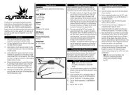
DRIVING YOUR MODEL• Transmission: Remove, disassemble,and clean the transmissioncomponents. No grease is requiredfor the nylon gears. Refer to yourexploded view diagrams for help withdisassembly and reassembly.• Motor: Remove the motor, cleanwith aerosol motor cleaner, and re-oilthe bushings (Titan 380 motor) orbearings (Velineon 380 motor) with lightweight motor oil. Be sureto wear eye protection when using spray aerosol cleaners.RECEIVER BOX: MAINTAINING A WATERTIGHT SEALRemoving and Installing Radio GearThe unique design of the receiver box allows the removal andinstallation of the receiver without losing the ability to maintain awatertight seal in the box. The patent-pending wire clamp featuregives you the ability to also install aftermarket radio systems andmaintain the watertight features of the receiver box.Removing the Receiver1. Remove the 2.5x8mm screws that secure the wire clamp.2. Remove the 2.5x8mm screws that secure the receiver box lid to thechassis. Lift the lid up and toward you to disengage the lid’s tab fromits slot in the chassis.3. You can now access the receiver. Unplug the servo cables from thereceiver and remove the receiver.AReceiver Installation1. Route the antenna wireout of the receiver boxcover (A). Place the coveron the chassis.2. Route the servo andspeed control leads into the receiver box cover.Use the molded-in wire guides to align theservo and speed control leads and antennawire (B).3. Apply a small bead of silicone grease (<strong>Traxxas</strong>part #1647) to the wire clamp (C).4. Install the wire clamp and tighten the two2.5x8mm screws securely (D).BCD5. Lift the receiver box cover and plugthe servo and speed control leads intothe receiver (E). Refer to page 9 for thewiring diagram.6. Bundle the wires so they fit beneath thereceiver box cover. You may secure thereceiver to the chassis with mounting tapeif you wish, but this is not required. Theexcess wire beneath the cover will preventthe receiver from rattling.7. Make sure the blue O-ring is properlyseated into the groove around the receivercover base so the cover will not pinch ordamage the O-ring. Snap the receiver boxcover into place (F).8. Inspect the cover to make sure the O-ringis not visible. If it is, remove the cover andreposition the O-ring. With the O-ring andcover properly seated, install the 2.5x8mmscrews and tighten them securely (G).EFG20 • TR A X X AS