
You also want an ePaper? Increase the reach of your titles
YUMPU automatically turns print PDFs into web optimized ePapers that Google loves.
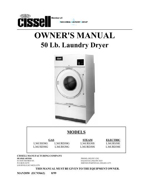
Member of:<strong>OWNER'S</strong> <strong>MANUAL</strong>50 Lb. <strong>Laundry</strong> DryerMODELSGAS STEAM ELECTRICL36USS30G L36URD30G L36URS30S L36URS30EL36USD30G L36URS30G L36URD30S L36URD30ECISSELL MANUFACTURING COMPANYHEADQUARTERS PHONE: (502) 587-1292831 SOUTH FIRST ST. SALES FAX: (502) 585-3625P.O. BOX 32270 SERVICE/PARTS FAX: (502) 681-1275LOUISVILLE, KY 40232-2270THIS <strong>MANUAL</strong> MUST BE GIVEN TO THE EQUIPMENT OWNER.MAN2050 (ECN5662) 8/99
IMPORTANT NOTICES—PLEASE READFor optimum efficiency and safety, we recommend that you read the manual before operating theequipment. Store this manual in a file or binder for future reference.WARNING: Purchaser must post the following notice in a prominent location:WARNING: For your safety, the information in this manual must be followed to minimizethe risk of fire or explosion or to prevent property damage, personal injury or death.- Do not store or use gasoline or other flammable vapors or liquids in the vicinity of this orany other appliance.- WHAT TO DO IF YOU SMELL GAS• Do not try to light any appliance.• Do not touch any electrical switch; do not use any phone in your building.• Clear the room, building, or area of all occupants.• Immediately call your gas supplier from a neighbor's phone. Follow the gassupplier's instructions.• If you cannot reach your gas supplier, call the fire department.Installation and service must be performed by a qualified installer, service agency or the gassupplier.WARNING: In the event the user smells gas odor, instructions on what to do must be posted in aprominent location. This information can be obtained from the local gas supplier.WARNING: Wear safety shoes to prevent injuries.WARNING: Purchaser must post the following notice in a prominent location:FOR YOUR SAFETYDo not store or use gasoline or other flammable vaporsand liquids in the vicinity of this or any other appliance.WARNING: A clothes dryer produces combustible lint and should be exhausted outside thebuilding. The dryer and the area around the dryer should be kept free of lint.WARNING: Be safe, before servicing machine, the main power should be shut off.Page 2
WARNING: To avoid fire hazard, do not dry articles containing foam rubber or similar texturematerials. Do not put into this dryer flammable items such as baby bed mattresses, throw rugs,undergarments (brassieres, etc.) and other items which use rubber as padding or backing. Rubber easilyoxidizes causing excessive heat and possible fire. These items should be air dried.WARNING: Synthetic solvent fumes from drycleaning machines create acids when drawn through thedryer. These fumes cause rusting of painted parts, pitting of bright or plated parts, and completelyremoves the zinc from galvanized parts, such as the tumbler basket. If drycleaning machines are in thesame area as the tumbler, the tumbler's make-up air must come from a source free of solvent fumes.WARNING: Do not operate without guards in place.WARNING: Check the lint trap often and clean as needed but at least a minimum of once per day.WARNING: Alterations to equipment may not be carried out without consulting with the factory andonly by a qualified engineer or technician. Only Manufacturer’s parts may be used.WARNING: Remove clothes from dryer as soon as it stops. This keeps wrinkles from setting in andreduces the possibility of spontaneous combustion.WARNING: Be Safe - shut main electrical power and gas supply off externally before attemptingservice.WARNING: Never use drycleaning solvents, gasoline, kerosene, or other flammable liquids in the dryer.FIRE AND EXPLOSION WILL OCCUR. NEVER PUT FABRICS TREATED WITH THESELIQUIDS INTO THE DRYER. NEVER USE THESE LIQUIDS NEAR THE DRYER..WARNING: Do not place items exposed to cooking oils in your dryer. Items contaminatedwith cooking oils may contribute to a chemical reaction that could cause a load to catch fire.WARNING: Never let children play near or operate the dryer. Serious injury could occur if a childshould crawl inside and the dryer is turned on.WARNING: Never tumble fiberglass materials in the dryer unless the labels say they are machinedryable. Glass fibers break and can remain in the dryer. These fibers cause skin irritation if theybecome mixed with other fabrics.WARNING: Before operating gas ignition system - purge air from natural gas or propane gas linesper manufacturer’s instructions.WARNING: To reduce the risk of electric shock, disconnect this appliance from the power supplybefore attempting any user maintenance other than cleaning the lint trap. Turning the controls to theOFF position does not disconnect this appliance from the power supply.Page 3
ATTENTION: L’ACHETEUR DOIT PLACER L’AVERTISSEMENTSUIVANT DANS UN ENDROIT CLAIR ET VISIBLE:AVERTISSEMENT. Assurez-vous de biensuivre les instructions donnees dans cettenotice pour reduire au minimum le risqued’incendie ou d’explosion ou pour eviter tuotdommage materiel, toute blessure ou la mort.__ Ne pas entreposer ni utiliser d’essence nid’autres vapeurs ou liquides inflammables dansle voisinage de cet appareil ou de tout autreapparell.__ QUE FAIRE SI VOUS SENTEZ UNEODEUR DE GAZ:• Ne pas tenter d’allumer d’apparell.• Ne touchez a aucun interrupteur. Ne pasvous servir des telephones se trouvant dansle batiment ou vous vous trouvez.• Evacuez la piece, le batiment ou la zone.• Appelez immediatement votre fournisseur degaz depuis un voisin. Suivez les instructionsdu fournisseur.• Si vous ne pouvez rejoindre le fournisseurde gaz, appelez le service des incendies.__ l’installation et l’entretien doivent etre assurespar un installateur ou un service d’entretienqualifie ou par le fournisseur de gaz.ATTENTION: L’ACHETEUR DOIT PLACER L’AVERTISSEMENTSUIVANT DANS UN ENDROIT CLAIR ET VISIBLE:POUR VOTRE SECURITENe pas entreposer ni utiliser d’ essenceni d’autres vapeurs ou liquidesinflammables dans le voisinage de cetappareil ou de tout autre appareil.Page 4
TABLE OF CONTENTS50 LB. LAUNDRY DRYERPAGEPAGEModel Numbers & Company Address ......................................... 1Important Notices ...................................................................... 2-4Dryer Warranty ............................................................................ 5Table of Contents ......................................................................... 6Warnings, Cautionary Notes and Symbols ................................. 7-8Unpacking and General Insulation ........................................... 9-10Dryer Outline Dimension (Illustration) ................................... 11-12Specifications ...................................................................... 113-16Motor List................................................................................... 17Electrical Connections ................................................................ 18Gas Piping Installation ........................................................... 19-20Gas Service Installation .............................................................. 21Gas Pipe Size Chart .................................................................... 22Steam Piping Installation ........................................................ 23-24Dryer Installation with Multiple Exhaust ................................ 25-26Dryer Make-Up Air Requirements ............................................. 27Dryer Installation with Separate Exhaust .................................... 28Exhaust and Venting................................................................... 29Rules for Safe Operation of Dryer ............................................. 30Coin Meter Model Operation Instructions.............................. 31-34Double Timer Model Operation Instructions ............................... 35Timer Models Control Panels ..................................................... 36Service Savers ............................................................................ 37Troubleshooting ..................................................................... 38-41Spark Ignition System ............................................................ 42-43General Maintenance ............................................................ 44-45Burner Air Inlet Shutters Adjustment .................................... 46-47Replacing Bearings Instructions ................................................ 48Basket Alignment .................................................................. 49-50Shimming the Basket and Spider Assembly ................................ 51Air Switch Adjustment ............................................................... 52Gear Reducer Information .......................................................... 53Duct Work and Air Switch Assembly ........................................ 54Dryers with Reversing Control Timer .................................... 55-56Front Panel and Door Assembly ................................................. 57Dryer - Front Exploded View ................................................ 58-59Single Motor Model - Rear View .......................................... 60-61Double Motor Model - Rear View ........................................ 62-63Bearings and Related Parts ........................................................ 64Small Gear Reducer ................................................................... 65Control Panel and Access Door - Two Timer ............................ 66Control Panel and Access Door - Coin Timer ............................ 67Reversing Control Panel Assembly ............................................ 68Thermostat Assembly ................................................................. 69Standard Gas Bonnet .................................................................. 70Energy-Saver Gas Bonnet .......................................................... 71Steam Heating Unit - Nine Section ............................................. 72Electric Heating Unit .................................................................. 73Electric Bonnet “UR” Model ...................................................... 74Electric Heating Circuit .............................................................. 75Page 6
SYMBOLSThe following symbols are used in this manual and/or on the machine.Symbol DescriptionNOTE!Hot! Do Not TouchHeiß! Nicht BeruhrenHaute temperature! Ne pastoucherCaliente! no tocardangerous voltagetension dangereuseGefährliche elektrischeSpannungtension peligrosaonmarcheEinconectadooffarrêtAusdesconectadostartdemarrageStartarranque de un movimientoemission of heat in generalêmission de chaleur engeneralWarmeabgabe allgemeinemisión de calorcoolingrefroidissementKühlenenfriamientoPage 7
SYMBOLSSymbol Descriptionrotation in two directionsrotation dans les deux sensDrehbewigung in zwei Richtungenmovimiento rotativo en los dossentidosdirection of rotationsens de mouvement continu de rotationDrehbewegung in Pfeilrichtungmovimiento giratorio o rotatorioen el sentido de la flechaEnd of CyclecautionattentionAchtungatencion; precaucionPage 8
UNPACKINGUnpacking/General Installation (All Dryers)Upon arrival of the equipment, any damage in shipment should bereported to the carrier immediately.Upon locating permanent location of a unit, care should be taken inmovement and placement of equipment.See outline clearance diagrams for correct dimensions.Remove all packing material such as: tape, manuals, skid, etcLeveling: Use spirit level on top of dryer. Adjust leveling bolts ondryer (see adjustable leveling bolts in maintenance section).Check voltage and amperes on rating plate before installing the dryer.GENERALINSTALLATION (ALLDRYERS)The construction of the dryers permits installation side-by-side tosave space or to provide a wall arrangement. Position dryer for theleast amount of exhaust piping and elbows, and allow free access tothe rear of dryer for future servicing of belts, pulleys and motors.Installation clearance from all combustable material is 0" ceilingclearance, 0" rear clearance, and 0" side clearance.Before operating dryer, open basket door and remove blockingbetween front panel and basket. Read the instruction tags, owner’smanual, warnings, etc.IMPORTANTOpening the clothes loading door deactivates the door switchto shut off the motors, fan, gas, steam, or electric element. Torestart the dryer, close the door and press in the push to startbutton and hold briefly.IMPORTANTThis dryer is designed for a capacity maximum load.Overloading it will result in long drying times and damp spotson some clothes.IMPORTANTMaximum operating efficiency is dependent upon proper aircirculation. The lint screen must be kept cleaned daily toinsure proper air circulation throughout the dryer.IMPORTANTProvide adequate clearance for air opening into the combustionchamber.Page 9
Unpacking/General Installation (All Dryers)GENERALINFORMATIONThe dryer is so designed that when an operator opens the dryerdoor, the basket and exhaust fan stop. You can expect fast dryingfrom a laundry dryer. Hot, dry air is properly and effectivelymoved through the basket and exhausted through a lint trap to theatmosphere. The dryer comes equipped with an inclined selfcleaninglint screen. In this system, lint accumulates on theunderside of the screen until a blanket of lint will fall from thescreen to the bottom of the dryer cabinet, and should be removeddaily or as required, to prevent an over-accumulation.IMPORTANTProvide adequate clearance for air openings into the combustionchamber.DRYER“COOL-DOWN”CYCLEPermanent press, durable press and other modern day fabricsrequire the care that your laundry dryers now provide. At the end ofthe drying cycle, a timed “Cool-Down” control automatically takesover and continues the rotation of the fan and basket without heatuntil the garment load reaches a safe cool temperature. Thisfunction is performed at the end of each drying cycle and continuesfor two minutes.REPLACEMENTPARTSReplacement parts for this dryer are available from your distributoror by contracting the factory at the address or phone number printedon the cover page of this manual.ONLY CISSELL PARTS SHOULD BE USED.Page 10
50 lb. Dryer Dimensions - Standard Gas, Steam and Electric Heated(Illustration)Page 11
50 lb. Dryer Dimensions - Gas Energy-Saver Model(Illustration)Page 12
Specifications - 50 lb. <strong>Laundry</strong> DryerGENERALSPECIFICATIONS FOR50 LB. LAUNDRYDRYERS (STANDARDGAS, STEAM, ANDELECTRIC HEATEDMODELS)Basket Load Capacity ...................................... 50 lb (23 kg)Floor Space (Single or Double Motor) .......... 75" (1905 mm) High37-7/8" (962 mm) Wide47-1/2" (1206 mm) DeepBasket Size ...................................................... 36" (914 mm) Diameter30-1/4" (768 mm) DeepExhaust Duct ................................................... 8" (203 mm) DiameterMotor Size ....................................................... See chart on page 16Maximum Air Displacement ........................... 800 cfm (1359 m³/h.)Recommended Operating Range .................... 630-730 cfm (1070 - 1240 m 3 /h )Basket Speed ................................................... Reversing - 42 rpm- 3.2 reversalsper minuteNon-reversing - 42 rpmExport Cube .................................................... 90.2 ft³ (2.6 m³)For total amps, check electrical rating plate on dryer.1. Can be designed forany voltage2. 50 Hz. or 60 Hz.3. 1 or 3 PhaseElectrical wiring to dryer must comply with local electrical code requirements.Page 13
Specifications - 50 lb. <strong>Laundry</strong> DryerGENERALSPECIFICATIONS FORGAS FIRED LAUNDRYDRYERSGas Supply ...................................... 1/2" (DN15) Pipe connectionHeat Input* (4 Burners) ................. 130,000 Btu/h (32,759 kcal/h) Natural gas130,000 Btu/h (32,759 kcal/h) Liquidpetroleum gasesDrying Time (Approx.) ................... 10 lb (4.5 kg) Dry weight(Indian Head) 100%moisture retention - 10 min.Net Weight (Approx.) .................... 545 lb (247 kg)Model with single motor599 lb (272 kg)Model with double motorDomestic Shipping Weight ........... 580 lb (263 kg)(1 Carton) Model with single motor634 lb (288 kg)Model with double motorExport Shipping Weight ................ 586 lb (266 kg)(1 Carton) Model with single motor671 lb (304 kg)Model with double motorExport Shipping Dimensions ......... 83" (2108 mm) Long45" (1143 mm) Wide55" (1397 mm) High* Input ratings as shown are for elevations up to 2,000 ft. (610 m). For higherelevations, ratings should be reduced 4% for each 1,000 ft. (305 m) above sealevel.ELECTRIC HEATEDLAUNDRY DRYERSHeater Input .................................... 30 kW/h (25,812 kcal/h)Drying Time (Approx.) ................... 12 lb (5.4 kg) Dry weight(Indian Head) 80%moisture retention - 12 min.Net Weight (Approx.) .................... 565 lb (256 kg)Model with single motor625 lb (283 kg)Model with double motorDomestic Shipping Weigh ............. 600 lb (272 kg)(1 Carton) Model with single motor650 lb (295 kg)Model with double motorExport Shipping Weight ................ 624 lb (283 kg)(1 Carton) Model with single motor660 lb (299 kg)Model with double motorExport Shipping Dimensions ......... 83" (2108 mm) Long45" (1143 mm) Wide55" (1397 mm) HighPage 14
Gas Energy-Saver <strong>Laundry</strong> Dryer SpecificationsGAS ENERGY-SAVERDRYERSPECIFICATIONSBasket Capacity ..................................... 50 lb (23 kg) Dry weightFloor Space ........................................... 75" (1905 mm) High53-1/2" (1359 mm) Deep37-7/8" (962 mm) WideBasket Size ............................................ 36" (914 mm) Diameter30" (762 mm) DeepExhaust Duct* ....................................... 6" (152 mm) DiameterExhaust Air Pressure ............................. Max. 0.3" (0.75 mbar)Static pressureMotor Size ............................................. See chart on page 16Basket Speed ......................................... Reversing - 42 rpm - 3.2reversals per minuteNon-reversing - 42 rpmMaximum Air Displacement ................. 450 cfm (764 m³/h)Heat Input .............................................. 104,000 Btu/h **26,208 kcal/hGas Supply ............................................. 1/2" (DN15) Pipe connectionDrying Time (Approx.) ......................... 10 lb (4.5 kg) Dry weight(Indian Head) 100%moisture retention - 10 min.Net Weight (Approx.) ........................... 640 lb (290 kg)Model with single motor690 lb (313 kg)Model with double motorDomestic Shipping Weight .................. 705 lb (320 kg)(Approx.)Model with single motor755 lb (342 kg)Model with double motorExport Shipping Weight ....................... 1180 lb (535 kg)(Approx.)Model with single motor1230 lb (558 kg)Model with double motor* For high altitude installation, remove the 5" (127mm) I.D.exhaust ring.** Input ratings as shown are for elevations up to 2,000 ft.(610 m). For higher elevations, ratings should be reduced4% for each 1,000 ft. (305 m) above sea levelGas burners are set at the factory at 3.5" W.C. (8.7 mbar) regulated pressure(Natural gas only).Models can be equipped for use with natural gas or liquid petroleum gases(L.P.)Electrical wiring to dryer must conform to local electrical code requirements.Page 15
Steam Heated SpecificationsGENERALSPECIFICATIONS FORSTEAM HEATEDLAUNDRY DRYERSMaximum Air Displacement ................. 800 cfm (1359 m³/h)Recommended Operating ..................... 630-730 cfmRange(1070 - 1240 m³/h)Steam Supply Connection .................... 3/4" (DN20)Steam Return Connection .................... 3/4" (DN20)Operating Steam Pressure ................... Low pressure - 7-15 psi(0.5 - 1 Bar)Maximum high pressure-100 psi (6.9 Bar)Drying Time (Approx.) ........................ 25 lb (11 kg) Dry weight(Indian Head) 80% moistureretention - 30 minutes lowpressure, 22 minutes highpressureSteam Consumption ............................. Low pressure - 2.9 BHP24,496 kcal/hHigh pressure - 3.8 BHP32,098 kcal/hNet Weight (Approx.) ........................... 595 lb (270 kg)Single motor655 lb (297 kg)Double motorExport Shipping Weight ....................... 630 lb (286 kg)(1 Carton) Single motor690 lb (313 kg)Double motorExport Shipping Weight ...................... 638 lb (289 kg)(1 Box) Single motor698 lb (317 kg)Double motorExport Shipping Dimensions ............... 83" (2108 mm) Long45" (1143 mm) Wide55" (1397 mm) HighPage 16
Motor Number List for 50 lb. Double and Single Motor ModelsMOTOR NUMBER LIST FOR 50 LB. DOUBLE MOTOR MODELSMotor No. Voltage Hz. Phase HP KWATTS Amps Basket/FanMTR300 115/200-240 60 1 1/2 .373 6.2/3.1 BMTR302 200-240/480 60 3 1/2 .373 1.8/.9 BMTR300 110/200-230 50 1 1/2 .373 7.4/3.7 BMTR302 240/415 50 3 1/2 .373 2.0/1.0 BMTR101 575 60 3 1 .75 1.7 BMTR302 220/380 50 3 1/2 .373 2.0/1.0 BMTR302 220/380 60 3 1/2 .373 1.8/.9 BMTR302 220/346 50 3 1/2 .373 2.0/1.0 BMTR302 220/380 60 3 1/2 .373 1.8/.9 FMTR302 200/346 50 3 1/2 .373 2.0/1.0 FMTR300 115/200-240 60 1 1/2 .373 6.2/3.1 FMTR300 110/200-230 50 1 1/2 .373 7.4/3.7 FMTR184 240/415 50 3 1/3 .25 1.6/.9 FMTR302 200-240/480 60 3 1/2 .373 1.8/.9 FMTR101 575 60 3 1 .75 1.7 FMTR302 220/380 50 3 1/2 .373 2.0/1.0 FMOTOR NUMBER LIST FOR 50 LB. SINGLE MOTOR MODELSMotor No. Voltage Hz. Phase HP KWATTS Amps Basket/FanMTR301 115/200-240 60 1 1 .75 9.0/4.9-4.5 B/FMTR301 110/200-230 50 1 1 .75 10.0/5.0 B/FMTR211 200-240/480 60 3 3/4 .56 3.2/1.6 B/FMTR303 240/415 50 3 1 .75 3.6/1.8 B/FMTR303 220/380 50 3 1 .75 3.6/1.8 B/FMTR303 220/380 60 3 1 .75 3.2/1.6 B/FMTR303 200/346 50 3 1 .75 3.6/1.8 B/FPage 17
Electrical Connections - All DryersELECTRICALCONNECTIONSDryers must be electrically grounded by a separate #14 or larger greenwire from the grounding terminal within the service connection box, toa cold water pipe. In all cases, the grounding method must complywith local electrical code requirements; or in the absence of localcodes, with the <strong>Nation</strong>al Electrical Code, ANSI/NFPA 70 or theCanadian Electrical Code, CA C22.1.See wiring diagram furnished with dryer. Your dryer is completelywired at the factory and it is only necessary for the electrician toconnect the power leads to the wire connectors within the serviceconnection box on the rear of the dryer. Do not change wiring withoutconsulting the factory, as you may void the factory warranty. DO NOTCONNECT THE DRYER TO ANY VOLTAGE OR CURRENTOTHER THAN THAT SPECIFIED ON THE DRYER RATINGPLATE. (Wiring diagram is located on rear wall of dryer.)All panels must be in position before operation of dryer.ELECTRICALCONTROLS SERVICECaution: Label all wires prior to disconnection when servicingcontrols. Wiring errors can cause improper and dangerous operation.Verify proper operation after servicing.«Attention. Lors des opérations d’entretiendes commandes, ètiqueter tous les fils avantde les dèconnecter. Toute erreur de câblagepeut être une source de danger et de panne»Page 18
Gas Piping InstallationGAS PIPINGINSTALLATION1. The installation must conform with local codes, or in theabsence of local codes with the <strong>Nation</strong>al Fuel Gas Code,ANSI Z223.1 or the CAN/CGA-B149, Installation Codes.2. Check identification nameplate for type of gas for dryer.3. Check the altitude of dryer.4. Check with utilities company for proper gas pressure and gassupply line.5. Natural gas only—check the gas pressure inlet supply todryer, 11 inches water column maximum. Manifoldpressure—3.5 inches water column (8.8 mbar) pressure.6. L.P. gas only—check the gas pressure inlet supply to dryer,13 inches water column(32.4 mbar) maximum. Manifoldpressure—11 inches water column (27.4 mbar) pressure.CAUTION: Low gas pressure and intermittent gas will causegas ignition problems and inadequate drying of laundry.Page 19
Gas Piping Installation (Illustrations)Gas shutoff valve is not supplied with dryer.The dryer and it’s individual shutoff valve must be disconnected from the gas supply piping systemduring any pressure testing of that system at test pressures in excess of 1/2 psi (3.5 kPa).The dryer must be isolated from the gas supply piping system by closing it's individual manual shutoffvalve during any pressure testing of the gas supply piping system at test pressures equal to or lessthan 1/2 psi (3.5 kPa).Page 20
Gas Service Installation InstructionsGAS SERVICEINSTALLATIONINSTRUCTIONSThe size of the gas service pipe is dependant upon many variables,such as tees, lengths, etc. Specific pipe size should be obtained fromthe gas supplier. Refer to the “Gas Pipe Size” chart in this manual forgeneral gas pipe size information.CAUTION: Gas loop piping must be installed as illustratedto maintain equal gas pressure for all dryers connected to asingle gas serviceOther gas-using appliances should be connected upstreamfrom the loop.WARNING:LIQUIFIED PETROLEUM GASES ONLY !GAS PRESSUREREGULATOR FORLIQUIFIEDPETROLEUM GASESA gas pressure regulator for liquified petroleum gases is notfurnished on gas heated clothes dryers. This regulator is normallyfurnished by the installer. In accordance with American GasAssociation (AGA) standards, a gas pressure regulator, wheninstalled indoors, must be equipped with a vent limiter or a vent linemust be installed from the gas pressure regulator vent to the outdoors.Page 21
Gas Pipe Size ChartTOTAL BTU/HR(for LP Gas correcttotal BTU/HR below bymultiplying by .6)TOTALKCALHOUR(25 ft.)7,62 mGAS PIPE SIZE FOR 1000 BTU (250 KCAL) NATURAL GASAT 7” (17.8 CM) W.C. PRESSUREIn figuring total length of pipe, make allowance for tees and elbows.(50 ft.) (75 ft.) (100 ft.) (125 ft.)15,24 m 22,86 m 30,48 m 38,1 m(150 ft.)45,72 m60,000150003/43/43/43/43/43/480,000200003/43/43/4111100,000252003/43/41111120,000302003/411111140,000352003/411111 1/4160,000403003/4111 1/41 1/41 1/4180,000453001111 1/41 1/41 1/4200,00050400111 1/41 1/41 1/41 1/2300,0007560011 1/41 1/41 1/21 1/21 1/2400,0001008001 1/41 1/41 1/21 1/21 1/22500,0001260001 1/41 1/21 1/2222600,0001512001 1/21 1/22222700,0001764001 1/222222 1/2800,0002020001 1/22222 1/22 1/2900,0002300002222 1/22 1/22 1/21,000,0002500002222 1/22 1/22 1/21,100,000270000222 1/22 1/22 1/22 1/21,200,000300000222 1/22 1/22 1/22 1/21,300,00033000022 1/22 1/22 1/22 1/231,400,00035000022 1/22 1/22 1/2331,500,00038000022 1/22 1/22 1/2331,600,00040000022 1/22 1/23331,700,00043000022 1/22 1/23331,800,0004500002 1/22 1/233331,900,0004800002 1/22 1/233332,000,0005040002 1/22 1/23333 1/22,200,0005500002 1/23333 1/23 1/22,400,0006050002 1/23333 1/23 1/22,600,0006500002 1/2333 1/23 1/23 1/22,800,0007050002 1/2333 1/23 1/23 1/23,000,0007500002 1/233 1/23 1/23 1/243,200,000806000333 1/23 1/23 1/243,400,00085000033 1/23 1/23 1/2443,600,00090700033 1/23 1/23 1/2443,800,00096000033 1/23 1/24444,000,000100000033 1/23 1/2444Page 22
Steam Piping - Installation InsatructionsSTEAM PIPING-INSTALLATIONINSTRUCTIONS1. Set and anchor dryer in position. Machine should be level to assure propersteam circulation.2. To prevent condensate draining from headers to dryer, piping should havea minimum 12" (305 mm) above respective header. Do not make steamconnection to header with a horizontal or downwardly facing tee or elbow.3. Whenever possible, horizontal runs of steam lines must drain, by gravity,to respective steam header. Water pockets, or an improperly drainedsteam header will provide wet steam, causing improper operation of dryer.If pockets or improper drainage cannot be eliminated, install a bypass trapto drain condensate from the low point in the steam supply header to thereturn.4. In both steam supply and steam return line, it is recommended that eachhave a 3/4" 20 mm) union and 3/4" (20 mm) globe valve. This will enableyou to disconnect the steam connections and service the dryer while yourplant is in operation.5. Before connecting trap and check valve to dryer, open globe valve insteam supply line and allow steam to flow through dryer to flush out anydirt and scale from dryer. This will assure proper operation of trap whenconnected.6. After flushing system, install bucket trap (with built-in strainer) and checkvalve. For successful operation of dryer, install trap 18" (457 mm) belowcoil and as near to the dryer as possible. Inspect trap carefully for inletand outlet markings and install according to trap manufacturer'sinstructions. If steam is gravity returned to boiler, omit trap but installcheck valve in return line near dryer.7. Install union and globe valve in return line and make final pipeconnections to return header.PIPINGRECOMMENDATIONS1. Trap each dryer individually. Always keep the trap clean and in goodworking condition.2. When dryer is on the end of a line of equipment, extend header at least 4feet beyond dryer. Install globe valve, union, check valve and bypass trap atend of line. If gravity returned to boiler, omit trap.3. Insulate steam supply and return line for safety of operator and safetywhile servicing dryer.4. Keep dryer in good working condition. Repair or replace any worn ordefective parts.Page 23
Steam Piping Installation (Illustration)Page 24
Dryer Installation With Multiple ExhaustFor Exhaust Duct less than 14 feet (5 m) and 2 elbowsequivalent and less than 0.3 inches (8 mm) static pressure.DRYER EXHAUSTSArea of section “A-A” must be equal to the sum of dryer exhaust pipes enteringmultiple exhaust pipe. (See chart below.)No. of dryersDuct diameter(in inches)(in cm)No. of dryersDuct diameter(in inches)(in cm)No. of dryersDuct diameter(in inches)(in cm)MODELS: L28FD30, L28US30, L36FD30, L36US30, L36US36, L44FD421 2 3 4 5 6 7 8 9 10 11 12 13 14 15 16 17 18 19 20 21 22 23 246 9 11 12 14 15 16 17 18 19 20 21 22 23 23 24 25 26 26 27 28 28 29 3015 23 27 30 35 38 41 43 46 48 51 53 56 58 58 61 63 66 66 68 71 71 73 76MODELS: L28CD30, L28UR30, L36CD30, L36UR30, L36UR36, L36AR36, L44FD421 2 3 4 5 6 7 8 9 10 11 12 13 14 15 16 17 18 19 20 21 22 23 248 121416182022232426272829303132333435363738394020 30 25 41 46 51 56 58 61 66 68 71 73 76 78 81 84 86 89 91 94 97 99100MODELS: L44CD42, L50CD421 2 3 4 5 6 7 8 9 10 11 1212 17 21 24 27 30 32 34 36 38 40 4230 43 53 61 68 76 81 86 91 97100106ExhaustBooster FanPower Supplyto FanRelay Coils_ _ _ __ _ _ __ _ _ __ _ _ __ _ _ __ _ _ _Start and StopSwitches onDryersPage 25
Dryer Installation with Multiple ExhaustDRYER INSTALLATIONWITH MULTIPLE EXHAUSTFor Exhaust Duct more than 14 feet (5 m) and 2 elbows equivalent andmore than 0.3 inches (8 mm) static pressure.(See illustration on next page.)1. Make-up air from outside building may enter enclosure from top orside walls. (See Dryer Make-Up Air Requirements Chart)2. Use constant diameter duct with area equal to the sum of dryer ductareas.EXAMPLE: 6-8 inch (203 mm) diameter duct = 1-19.6 inches (498mm) diameter duct in area. Use 20 inches (508 mm) diameter duct ordiameter to match tube-axial fan.3. Enclosure (plenum) with service door. This separates the dryer air fromroom comfort air. If dryers use room air instead of outside air, the heatloss can be another 25 Btu/h (6.3 kcal/h) for each cubic foot per minute(cfm) used.4. Zero inches clearance to combustible material allowed on sides and atpoints within 4 inches (100 mm) of front on top.5. Heat loss into laundry room from dryer fronts only is about 60 Btu/hper square foot (15 kcal/h per 0.1m²).6. Flange mounted, belt driven tube-axial fan. Fan must run when one ormore dryers are running. See suggested Automatic Electrical ControlWiring Diagram on previous page. Must meet local electrical codes.Fan air flow (cfm) (m³/min.) is equal to sum of dryer air flows, butstatic pressure (SP) is dependent on length of pipe and number ofelbows.7. Barometric bypass damper—Adjust to closed flutter position with alldryers and exhaust fan running. Must be located within enclosureCAUTION: Never install hot water heaters or other gas appliancesin the same room as dryers. Never install cooling exhaust fans in thesame room as dryers.CAUTION: Never exhaust dryers with other types of equipment.Page 26
Suggested Minimum Dryer Make-up Air RequirementsDryerDryer Pocket Maximum AirDuct Size RequiredModelCapacity Flow RateFor Service Make-up Airper Pocket Connection Area per Pocketlbkg cfmm3/hinchmmsq. inch cm2C 30 30 13.6 700 1190 8 203 135 871C 30 E/S 30 13.6 400 680 6 153 77 497C 30 ST 30 13.6 450 765 6 153 87 561C 50 50 22.7 800 1360 8 203 154 994C 50 E/S 50 22.7 450 765 6 153 87 561C 75 75 34 1000 1700 8 203 192 1239C 75 E/S 75 34 536 911 6 153 103 665C 75 ST 75 34 1000 1700 12 305 192 1239HD80 80 36.3 1465 2490 10 254 282 1819C 110 110 50 2200 3740 12 305 422 2723C 110 E/S 110 50 850 1445 8 203 163 1052C 125 125 56.7 2000 3400 12 305 384 2477C 150 150 68 2250 3825 12 305 432 2787HD175 175 79.4 2780 4726 12 305 534 3445HD190 190 86.2 3000 5100 12 305 576 3716HD20 20 9.1 450 765 6 153 87 561HD30 30 13.6 625 1063 8 203 120 774HD50 50 22.7 700 1190 8 203 135 871HD75 75 34 750 1275 8 203 144 929Notes:1) The Model C 30 ST has 2 pockets per dryer, each pocket has the above listed characteristics;each pocket is exhausted separately with a 6" (152 mm) duct.2) The Model C 75 ST has 2 pockets per dryer, each pocket has the above listed characteristics;both pockets have one 8" (203 mm) exhaust manifolded into one 12" (305 mm) exhaustduct for connection.3) For the C 30 ST and the C 75 ST Models, the Required Make-up Air Area shown in the tableshould be doubled since it is shown per pocket, only.4) E/S indicates an Energy Saving Model.Page 27
Dryer Installation With Separate Exhaust (Preferred)DRYER INSTALLATIONWITH SEPARATE EXHAUST(PREFERRED)For ductwork less than 14 feet (5 m) and 2 elbows equivalent and less than0.3 inches (8 mm) static pressure:NEVER exhaust the dryer into a chimney.NEVER install wire mesh screen over the exhaust or make-up airarea.NEVER exhaust into a wall, ceiling, or concealed space.1. Make-up air opening from outside the building may enter the enclosurefrom the top or side walls. (See Dryer Make-Up Air RequirementsChart)2. Enclosure (plenum) with service door. This separates the dryer air fromthe room comfort air. If dryers use room air instead of outside air,additional heat loss can be another 25 Btu/h (6.3 kcal/h) for each cubicfoot per minute (cfm) (.03m³/min.) used.3. Zero inches (mm) clearance to combustible material allowed on sidesand at points within 4 inches (100 mm) of front on top.4. Heat loss into laundry room from dryer front panels is about 60 Btu/hper square foot (15 kcal/h per 0.1m²).Page 28
Exhaust and VentingDRYER AIR FLOWINSTALLATIONEXHAUST DUCTMAKE-UP AIROTHERRECOMMENDATIONSTROUBLESHOOTINGNothing is more important than air flow for the proper operation of a clothesdryer. A dryer is a pump which draws make-up air from the out-of-doors,through the heater, through the clothes and then forces the air through theexhaust duct back to the out-of-doors. Just as in a fluid water pump, there mustbe a fluid air flow to the inlet of the dryer, if there is to be the proper fluid airflow out of the exhaust duct.In summary, there must be the proper size out-of-doors inlet air opening (4-6times the combined areas of the air outlet) and an exhaust duct, size and lengthof which allows flow through the dryer with no more than 0.3” w.c.(.8 mbar) pressure in the exhaust duct.In some instances, special fans are required to supply make-up air, and/or boostexhaust fans are required for both regular and energy saving models.FOR BEST DRYING:1. Exhaust duct maximum length 14 feet (5 m) of straight duct andmaximum of two 90° bends.2. Use 45° and 30° elbows wherever possible.3. Exhaust each dryer separately.4. Use 2 feet (0.6 m) of straight duct on dryer before installing an elbowon energy-saver models only.5. Do not install wire mesh or other restrictions in the exhaust duct.6. Use clean-outs in the exhaust duct and clean periodically when needed.7. Never exceed 0.3” water column (.8 mbar) static pressure in theexhaust duct.8. Inside surface of the duct must be smooth.9. Recommend pop rivets for duct assembly.FOR BEST DRYING:1. Provide opening to the out-of-doors in accordance with the following:For each dryer—6 inches (152 mm) diameter exhaust requires a 1 square feet (0.1 m²)opening for make-up air.8 inches (203 mm) diameter exhaust requires a 2 square feet (0.2 m 2 )opening for make-up air.12 inches (305 mm) diameter exhaust requires a 4 square feet (0.4 m 2 )opening for make-up air.2. Use barometric shutters in the inlet air opening to control air whendryers are not running.Other RecommendationsTo assure compliance, consult local building code requirements.TroubleshootingHot dryer surfaces, scorched clothes, slow drying, lint accumulations, or airswitch malfunction are indicators of exhaust duct and/or make-up air problems.Page 29
Rules for Safe Operation of DryerRULES FOR SAFEOPERATION OF DRYER1. Be sure your dryer is installed properly in accordance with therecommended instructions.2. CAUTIONBe safe—shut main electrical power supply and gas supply offexternally before attempting service.3. CAUTIONNever use drycleaning solvents: gasoline, kerosene, or other flammableliquids in the dryer. Fire and explosion will occur.Never put fabrics treated with these liquids into the dryer.Never use these liquids near the dryer.Always keep the lint screen clean.Never use heat to dry items that contain plastic, foam or sponge rubber,or rags coated with oils, waxes or paints. The heat may damage thematerial or create a fire hazard. Rubber easily oxidizes, causingexcessive heat and possible fire.Never dry the above items in the dryer.4. Never let children play near or operate the dryer. Serious injury willoccur if a child should crawl inside and the dryer is turned on.5. Never use dryer door opening and top as a step stool.6. Read and follow manufacturer’s instructions on packages of laundry andcleaning aids. Heed any warnings or precautions.7. Never tumble fiberglass materials in the dryer unless the labels saythey are machine dryable. Glass fibers break and can remain in the dryerand could cause skin irritation if they become mixed into other fabrics.8. Reference: Lighting and shut-down instructions and wiring diagramsare located on the rear wall of the dryer cabinet.9. The dryer must not be installed or stored in an area where it will beexposed to water and/or weather.ENERGY-SAVING TIPS1. Install dryer so that you can use short, straight venting. Turned elbowsand long vent tubing tend to increase drying time. Longer drying timemeans the use of more energy and higher operating costs.2. Operate dryer using full-size loads. Very large loads use extra energy.Very small loads waste energy.3. Dry light-weight fabrics separately from heavy fabrics. You will useless energy and get more even drying results by drying fabrics ofsimilar weight together.4. Clean the lint screen area daily. A clean lint screen helps give faster,more economical drying.5. Do not open the dryer door while drying. You let warm air escape fromthe dryer into the room.6. Unload the dryer as soon as it stops. This saves having to re-start yourdryer to remove wrinkles.Page 30
Operating Instructions—Coin Meter ModelsOPERATINGINSTRUCTIONS—COINMETER MODELSOPERATING INSTRUCTIONS—COIN METER MODELS1. After loading the dryer with water washed clothes, close the loadingdoor.2. ELECTRO-MECHANICAL COIN METER: Insert proper coin(s) inslot and turn knob until it stops.COMPUTERIZED COIN METER: Insert coin. Amount of dryingtime will appear on the digital display. Maximum time is 99 minutes.Additional coins may be vended any time during the cycle.3. Select temperature setting using proper push button.HIGH—185° F (85° C) exhaust temperature, heavy fabrics and hardto dry, (cottons and linens).MEDIUM—150°F (66° C) exhaust temperature, permanent press,synthetic blends.LOW—135°F (58° C) exhaust temperature, delicate, sheer fabrics.4. Press the “Start” button to start the drying and cooling cycles.ELECTRO-MECHANICAL COIN METERCOMPUTERIZED COIN METERWHAT IS HAPPENING AFTER STEP 4:1. Digital display will count down time remaining in cycle (computerizedcoin meter).2. The fan motor and basket will revolve.3. The heat source will be energized.4. The heated air will mix with the wet clothes and evaporate the moisture.5. The thermostats will operate at a safe temperature.6. The heat will shut off and the cooling cycle will begin.Page 31
Operating Instructions—Coin Meter ModelsIMPORTANTIMPORTANTIf the tumbler door is opened during the drying cycle, the fan andheat will shut off. Press “START” button to resume the cycle.This dryer is designed for a capacity maximum load. Overloadingit will result in longer drying time and damp spots on some of theload.Maximum operating efficiency depends on proper air flow. Thelint screen must be kept clean daily to insure proper circulationof air throughout the dryer.This commercial dryer has keys for the lint door and access doorto burners and controls. This is for the safety of the user.Page 32
Setting Time On Computerized Coin Meter (Illustration)INSTRUCTIONS FOR SETTING TIME ON “COMPUTERIZED COIN METER”DIP Switch Banks are located herePage 33
Setting Time On Computerized Coin MeterINSTRUCTIONS FORSETTING TIME ONCOMPUTERIZED COINMETER1. This dryer is equipped with two banks of four DIP switcheseach.2. Each DIP switch bank consists of 4 small switches each with aspecified amount of time (minutes), as shown:ON1 min.OFF2 min. 4 min. 8 min.3. To set the time on the DIP bank simply set the appropriateswitch to the ON (up) position to total the desired amount oftime.NOTEOFF (down) position equals 0 minute.EXAMPLE: 25¢ for 12 minutesMINUTES:0 + 0 + 4 + 8 = 12 min.Page 34
Operating Instructions—Double Timer ModelsOPERATINGINSTRUCTIONSDOUBLE TIMERMODELSOPERATING INSTRUCTIONS—DOUBLE TIMER MODELSStep 1.After loading the dryer with water washed clothes,close the loading door.Step 2.Step 3.Step 4.Turn the 60 minute drying (heat) timer to the desiredtime. The drying cycle light will be on.Turn the 15 minute cooling (air) to the desired time.The cooling light will come on after the dryingfinishes.Select the temperature desired:High Heat185° F (85° C) exhaust temperature, heavy fabrics andhard to dry.Normal185° F (85° C) exhaust temperature, cottons andlinens.Permanent Press150° F (66° C) exhaust temperature, synthetic blends.Low Heat135° F (58° C) exhaust temperature, delicate, sheerfabrics.Step 5.Step 6.Turn “on/off” toggle switch to “on” and press the“push to start” button to start the drying and coolingcycles.To shut the dryer off at any time during the cycles,switch the “on/off” switch to “off”.Page 35
Double Timer Models (Illustration)Double Timer PanelPage 36
Service SaversTROUBLESHOOTINGDRYER WON’T STARTDRYER WON’T HEATCLOTHES ARE NOTSATISFACTORILY DRYTo help you troubleshoot the dryer, listed below are the mostcommon reasons for service calls and some answers to theproblems. Before you call service, please review the followingitems:DRYER WON’T START1. Is the door completely closed?2. Are the controls set to the “on” position?3. Did you push the “start” control?4. Has a fuse blown or a circuit breaker tripped?5. Are the fuses tight?6. Check for low voltage.7. Has the bonnet thermostat (gas only) tripped? If so, push toreset.DRYER WON’T HEAT1. Is the dryer set for “cooling time” rather than “dryingtime”?2. Are the gas valves in the dryer and in the main gas lineturned on?3. Check for low or intermittant gas pressure.4. Check spark ignition module diagnostic light.CLOTHES ARE NOT SATISFACTORILY DRY1. Timed cycle—Did you allow enough heating time beforethe cool-down part of the cycle?2. Is the lint screen blocked?3. Is the exhaust duct to the outside clean and not blocked? (Ablocked exhaust will cause slow drying and otherproblems.)GAS DRYER IGNITIONGAS DRYER IGNITIONRefer to the page on “Instructions for the direct ignitionsystem operation”. Check to see if the manual gas valve isopen. Then reset the dryer controls. All panels, covers, anddoors must be in place and closed before starting the dryer.VERY IMPORTANTWhen calling the factory for service, always refer to themodel number and serial number.Page 37
Troubleshooting ChartTROUBLE CAUSE REMEDYMotor will not start.Motor tripping on thermaloverload.Basket motor will not run.No power.Incorrect power.Time off.Loose wiringconnections.Defective startingrelay.Low voltage.Inadequate wiring.Loose connections.Inadequate air.Poor housekeeping.Loading door open.Check fuses on circuit breakers. Make sure maincontrol switch is on.Check power source; voltage, phase and frequencymust be the same as specified on electrical rating plate.Turn timer clockwise to desired time setting.Check wire connections in electrical box on rear ofdryer.Check coils and contacts.Check voltage at motor terminals. Voltage must bewithin + 10% of voltage shown on motor rating plate. Ifnot, check with local power company for recommendedcorrective measures.Check with local power company to insure that wiringis adequately sized for load.Check all electrical connections and tighten any looseconnections.Check installation sheet in service manual for recommendedmake-up air openings.Clean lint accumulation on and around motors.Close door.Dryer does not stop at endof time period.Motor runs, but basket willnot revolve.Door switch out ofadjustment.Defective doorswitch.Defective basketmotor contractor.Defective timer.V-belt broken.V-belt loose.Motor pulley loose.Basket overloaded.Adjust switch by removing cover and bend actuatorlever to clear switch button 3/8" (10 mm) with cover inplace.Replace switch.Replace contactor.Replace timer.Replace V-belt.Adjust belt tension.Tighten set screw.Remove load.Page 38
Troubleshooting ChartTROUBLE CAUSE REMEDYDryer noisy or vibrating.Dryer runs, but no heat.Not leveled.Fan out of balance.Basket rubbing.V-belt sheaves.Belt.Foreign objects.Incorrect voltage.No voltage.Defective gas valve.gas turned off.Defective doorswitch.Air switch notoperating.Check manual for proper leveling procedures.Accidental damage to the fan blade can change thedynamic balance. Damaged fans should be replaced.Adjust basket clearance.Tighten set screws. Make sure sheaves are in properalignment.Adjust belt tension.Occcasionally screws, nails, etc., will hang in thebasket perforations and drag against the sweep sheetssurrounding the basket. Such foreign objects shouldbe removed immediately.Check for correct control voltage - 120V.Check power supply, check secondary voltage ontransformer and check wiring and wiring diagram.Replace coil assembly.Turn manual gas valve on.Replace door switch.Clean out lint compartment daily. Check back draftdamper for foreign objects, lint accumulation or othercauses that may prevent damper from operating.Check duct work for lint build-up. Check installationsheet to insure that duct work and make-up air openingsare adequately sized. Check exhaust outlet. If ascreen has been improperly installed on the outlet, itmay be clogged with lint or frozen over in winter.Never install a screen on the exhaust outlet. Vacuumwithin dryer drops to .09 inches (3 mm) or watercolumn, or less, for normal operation of dryer, vacuumreading can be made with a vacuum u-gauge byremoving a sheet metal screw in the front panel ofdryer, and inserting the rubber tube of the vacuumgauge into screw opening.Page 39
Troubleshooting ChartDryer runs, but no heat.(continued)Main burners burningimproperly.Low or high gas flame.Dryer too hot.TROUBLE CAUSE REMEDYAir switch out ofadjustment.Air switch defective.Gas pressure too low.Improper orifice.Direct spark ignitionmodule defective.Electric power toheating unit turnedoff.Line fuse or heatercircuit fuse blown tounit.Defective relay.Defective electricelements.Defective thermostat.Defective safetyoverload thermostat.Lint compartmentdoor open.Burner air shuttersclosed.Dirt in burner.High gas pressure.Orifice too large.Restricted or blockedexhaust.Incorrect mainburner orifices.Incorrect mainburner orifice.Inadequate make-upair.Lint accumulated.Exhaust ductdampers.High gas pressure.Partially restricted orinadequately sizedexhaust system.See air switch adjustment sheet in service manual.Replace air switch.Check manifold pressure and adjust to pressure specifiedon rating plate. If this pressure cannot be obtained, havegas supplier check main pressure.Orifices have been sized for the type of gas specified onrating plate. Check with gas supplier to determinespecifications for gas being used. If different from ratingplate, contact factory and obtain proper orifices.Replace direct spark ignition moduleTurn power on.Replace fuseReplace relay.Replace elements.Replace thermostat.Replace thermostat.Close door.Open for blue flame.Blow out.Adjust gas pressure per rating plate.Send to factory for correct orifices.Clean exhaust.Replace orifices. Check factory for correct size.Replace orifices. Check factory for correct size.Make-up air must be 4 to 6 times the exhaust area of thedryer.Remove lint.Must be full open or replace.Adjust gas pressure per rating plate.Check service manual for recommended sizes. Removeobstructions or lint build up from duct work. NEVER usesmaller size exhaust duct. ALWAYS use larger size.Page 40
Troubleshooting ChartTROUBLE CAUSE REMEDYDryer does not stop at endof time period (6).Dryer runs no steam tocoils.Water in steam line.Basket does not reverse.Defective timer.Valve closed.Steam trap blocked.Solenoid valve.Thermostat.Check valve installedincorrectly.Strainer clogged.Steam pipinginstalled incorrectly.Trap not functioning.Reversing timer.Replace timer.Check all valves in steam supply and return. Makesure they are open.Remove and clean. Replace if defective.On dryers using solenoid temperature control, thermostatcontrols operation of solenoid valve by advancingthermostat.On dryers using solenoid temperature control, thermostatcontrols operation of solenoid valve. If defective,replace thermostat.Check for inlet and outlet marking on check valve andinvert if necessary.Remove plug and blow down strainer or remove andclean thoroughly if heavily clogged.Check piping per steam installation instructions.Check trap for size and capacity. If dirty and sluggish,clean thoroughly or replace. Check return linefor high back pressure, or another trap chargingagainst the trap functioning improperly.Check timer to see if operating.Page 41
Direct-Spark Ignition OperationDIRECT SPARKIGNITIONOPERATIONNOTE:Some models are equipped with a dual ignition system.The dual ignition system contains two direct sparkignition modules in parallel. Each module has its ownflame sense circuit and acts independently of the other.If either bonnet limit thermostat opens because of highheat or flame impingement, the entire ignition systemwill shut down.1. When a call for heat is received from the control supplying24VAC to the ignition control module, the pre-purge delaytimer begins. This delay time allows any air/sediment to beejected prior to burner ignition. Following the pre-purge delayperiod, the gas valve is energized and the spark ignitor sparksfor the trial ignition period.2. When a flame is detected during the trial for ignition period, thespark ignitor shuts off and the gas valve remains energized.3. If no flame is detected by the flame sense circuit, the ignitioncontrol module will go into safety lockout. The valve will beturned off immediately. If the module has multiple retries andno flame is detected, the gas valve is de-energized and themodule goes into an interpurge delay. After this delay, themodule will attempt another trial for the ignition period. Thiswill continue until the number of retries has been used up. Atthe time, the module will go into safety lockout.4. Recovery from safety lockout requires one of the following:a. A manual reset by opening and closing the loading door.b. After one hour if the control thermostat is still calling forheat, the module will automatically reset and the trial forignition period will start over.5. Opening the loading door will cause the flame to extinguish.Closing the door and starting the dryer will restart the trial forignition period.6. Once the control thermostat has been satisfied and/or thedrying timer has been timed out, the ignition controlmodule(s) will be de-energized, the gas valve(s) will be deenergizedand the flames will extinguish.7. The machine will continue to run in a cooldown mode withoutheat. This process will cool the load to the touch and help toeliminate wrinkling.Page 42
DIRECT SPARKIGNITION OPERATIONFLOW CHARTPage 43
General MaintenanceGENERALMAINTENANCE1. Clean lint trap daily. Remove lint before or after each day ofoperation. A clean lint trap will increase the efficiency of thedryer and the moisture-laden air will be exhausted outside morequickly.2. Keep basket and sweep sheets clean. Clean as often asneeded. The basket and sweep sheets are accessible byremoving the front panel of the dryer.3. Gas burners, steam coils, electric coils. Check and clean often.4. Pulleys and belts. Keep clean, as oil and dirt will shorten thelife of a belt. Check periodically for alignment. Pulley shaftsmust be parallel and the grooves must be aligned. Check belttension periodically. Adjust tension by movement of idlerbracket. Lubricate idler pulley once every two months, using sixgrams of high temperature grease. Do not over-grease.5. Electric motor. Keep motor clean and dry. Motors are packedwith sufficient grease for 10 years normal service. After that,bearings and housing should be cleaned and repacked one-thirdfull with Chevron grease No. SR1-2. See label on motor forfurther information.If motor overheats, check voltage and wiring. Low voltage,inadequate wiring and loose connections are the main cause ofmotor failures.6. Adjustable leveling bolts. One at each corner permits accuratealignment of dryer.To adjust: Block one corner of dryer up off the floor, loosenhex nut. With wrench, turn bolt clockwise to raise dryer,opposite to lower. Rear bolts are outside of dryer and frontbolts are inside lint trap compartment.Page 44
General MaintenanceGENERALMAINTENANCE(continued)7. Periodically clean and examine exhaust system.8. Keep dryer area clean and free of gasoline, combustiblematerials and other flammable liquids or vapors.9. Do not obstruct the flow of combustion (make-up) air andventilating air.10. Check gas pressure periodically.11. Gas burner air inlet shutters can be adjusted for proper flameby following instructions outlined on separate page of thismanual.12. Main Basket Bearings. Lubricate once every six months,using six grams of high temperature grease. Do not overgrease.13. Steam Heating Units. Keep steam coils clean. Checkperiodically and clean as often as required. Remove lint anddirt accumulation from coil fins to avoid decreasing theirefficiency.14. Clean Out Panel (Energy Saver Gas Models Only). Removethis panel, located on the energy saver heating unit, and cleanthe inside area of lint and dirt on a regular basis.Page 45
Burner Air Inlet Shutter Adjustment (w/Illustrations)BURNER AIR INLETSHUTTERADJUSTMENTBurner air inlet shutters are correctly adjusted when the flame isprimarily blue.Type of GasNatural gasLiquid petroleumManufactured gasBurner Air InletShutter AdjustmentWide open1/2 Open1/8 OpenAIR SHUTTERADJUSTMENTAir Shutter AdjustmentProper methodClose air shutters to yellow tip, then open air shutters to blue flametip. Orange tips are impurities in the air such as lint, dust, etc.CORRECTPage 46
Burner Air Inlet Shutter AdjustmentNEED TO ADJUSTSHUTTERNeed to Adjust ShutterBurners air inlet shutters are adjusted insufficient; air is admittedthrough the burner. Flame pattern is straight up and flame is yellow.WRONG--NEED TO ADJUST SHUTTERNEED TOPROVIDECORRECTAIR FLOWTHROUGH THEDRYERNeed to Provide Correct Airflow Through the DryerThis flame pattern indicates the burner air inlet shutters are correctlyadjusted, but air through the dryer is insufficient. This conditionindicates excessive lint in the lint compartment, lack of make-up air inthe room, restricted exhaust duct, or a vacuum in the room caused byan exhaust fan.WRONG--NEED TO PROVIDE CORRECT AIR-FLOW THROUGH THE DRYERPage 47
Replacing Bearings and Collars InstructionsOperating ConditionsCleanDirtyMoistureGrease IntervalsEvery 6 monthsEvery monthEvery weekREPLACINGBEARINGS ANDCOLLARSINSTRUCTIONSStep 1Step 2Step 3Step 4Step 5Step 6Remove belt guard, V-belt, spacer and basketsheave.Loosen set screws on the flange bearing and on thepillow block bearing.Remove the bolts holding the pillow block bearingand take it off the shaft.Remove the nuts and washers holding the flangebasket bearing and take it off the dryer.Inspect the bearings for damage and replace asnecessary, in reverse order of removing them. Beforetightening securely, align basket per instructions onseparate instruction sheet.Lubrication guide—Bearings never need lubrication.They have been permanently lubricated by thesupplier with a high temperature grease.Page 48
Basket Alignment—Double Motor ModelBASKET ALIGNMENTDOUBLE MOTORMODELStep 1Step 2Step 3Step 4Loosen the 4 gear reducer mounting bolts (1, 2, 3, &4) on rear of dryer, and 2 adjusting bolts #5, on gearreducer housing. (figure 3)Place one “A” and two “B” diameter pins inside thedrying compartment between the rim of the basketopening and the rim of the door opening, in thepositions shown in figure 1 and figure 2. Check thetwo “B” pins for equal clearance.With the pins in position, tighten the two “5” boltsuntil flush against back of dryer. Retighten gearreducer mounting bolts in the numerical orderindicated in figure 3. Tighten lock nuts “6” to securebolts “5” in position. Then remove pins.Check the space between basket and door openingat “A” pin and “B” pin positions (figure 2). If thegap is not approximately the same on both sides; repeatSteps 1, 2, & 3.NOTEUse short sections of round steel rod for pins, or drill bitsmay be used in place of round rod.Page 49
Basket Alignment—Single Motor ModelBASKET ALIGNMENTSINGLE MOTORMODELStep 1Step 2Step 3Loosen the set screws on the flange and pillow block bearings.Loosen the 4 side bolts, “1, 2, 3, 4,” on the basket bearingbracket. (see figure 3) Loosen the two adjusting bolts andlocknuts “5, 6,” inside the bracket. And loosen the bolts “7,” onthe pillow block bearing.Place one “A” and two “B” diameter pins inside the dryingcompartment between the rim of the basket opening and the rimof the door opening in the positions shown in figures 1 and 2.Check the two “B” pins for equal clearance.NOTEPush the basket toward the rear.Step 4Step 5Step 6With the pins in position, tighten the set screws on the bearingraces.Tighten the side bolts “1, 2, 3, 4,” in numerical order. Tightenthe bolts “7” on the pillow block bearing. And tighten the bolts“5” and locknuts “6”.Remove the aligning pins.CAUTIONCheck to see that the set screws are wrench tight on the bearings.Page 50
Basket Shimming InstructionsBASKET SHIMMINGINSTRUCTIONSThis procedure is normally necessary when replacing either the basket or thespider assembly on any dryer. Proper shimming is crucial to obtain a truerunning basket.A. Align the basket as per instructions in the manual.B. Rotate the basket to determine where the most out-of-roundpoint is (where the basket scrapes or comes closest toscraping the sweep sheet).C. Mark this position and the nearest rib to this position.D. Remove the basket (do not loosen the alignment bolts).E. With the basket on the floor (spider up), place one or twoshims between the spider leg and the back of the basket atthe marked rib position. (see drawing)F. Re-insert spider and basket assembly and re-check cylinder.G. If at this point, basket is still out-of-round, procedure mustbe repeated starting with Step B.Upon completion of shimming process, realignment of basket isnecessary.NOTEIf the point mentioned in Step B is between two ribs, both ribsmight have to be shimmed.Page 51
Air Switch Adjustment (with Illustration)AIR SWITCHADJUSTMENT1. Shut off current; disconnect leads and remove air switch.2. Lay air switch assembly on flat surface. Adjust air blade at“A” (figure 1), so that air blade lays flat and surface “B” isparallel to the flat surface.3. Place 3/8" (10 mm) x 5/8" (16 mm) spacer bar or equivalent “C”(figure 2), under air blade in position shown; hold switchmounting bracket firmly and adjust switch actuator “D” withneedle nose pliers at “E” by twisting actuator right or left,whichever is needed, so that switch closes when end of airblade engages bar “C”.4. Maximum opening of air switch must be no greater than 3/4"(figure 3). Bend tab “F” in or out to maintain this dimension.5. Re-install air switch assembly on rear of dryer.6. Re-check operation of air blade. Switch must close before airblade engages face of opening and re-open before stop “F”engages.Page 52
Gear Reducer InformationOPERATION ANDMAINTENANCEOPERATION AND MAINTENANCEAfter Start UpThe Gear reducer is shipped filled with oil to the right level and after twoweeks or 100 hours of operation, drain the oil, and flush the gear reducer witha light flushing oil. The original oil can be used for re-filling if it has beenfiltered; otherwise, new oil must be used. After this, change the oil every sixmonths or 2500 hours of operation.CAUTION• USE AGMA 8EP TYPE OIL; CISSELL PART #TU3465ONLY ! !. The gear reducer is equipped with two oil plugs located on the rightside as viewed from the back of the dryer.• To change oil: remove the lower oil plug and drain the used oil.• Re-install the lower oil plug and remove the upper oil plug. Addnew oil until the oil starts to spill out. Re-install the upper oil plug.Page 53
Parts—Duct Work and Air Switch Assembly—TU8206 (with Illustrations)Duct Work Parts1 TU8053 Duct Elbow2 TU8055 Duct Long3 TU8052 Duct Tee5 TU7375 Extended Elbow6 TU8177 Duct Short7 TU9161 Installation Label1 F888 “E” Ring2 TU2463 Actuator Arm3 TU3476 Air Switch Decal4 TU1771 #6 Tinnerman Nut5 TU8155 Air Switch6 TU1770 Insulator7 TU8171 Air Switch Bracket8 TU7733 #8 - 18 x 1/2" Self Drilling Screw9 TU3219 #6 x 1" Round Head S.M.S.Air Switch AssemblyTU8206Page 54
Dryers with Reversing Control TimerINSTRUCTIONS FORDRYERS WITHREVERSINGCONTROL TIMERInstructionIn operation, coasting of basket increases, making it necessary to readjustreversing timer.CAUTIONFailure to do this will cause the thermal overload units for the basket tocut-out unnecessarily and probably damage the gear reducer.Adjustment of reversing timer dwell timeCAUTIONDryer power supply must be shut off before adjusting timer.The dwell time is the time from when the motor turns “off”, to when it turns“on” again in the opposite direction.Turning the dwell adjustment knob counter-clockwise increases the dwell timeand turning it clockwise decreases the dwell time.Recommended dwell time for the basket to stop completely is 5 to 7 seconds.Minimum basket stopping time is 4 seconds.NOTE:Select non-reversing or reversing before starting dryer.Page 55
Dryers with Reversing Control Timer (Illustration)INSTRUCTIONS FORDRYERS WITHOUTREVERSINGCONTROL FAN ANDBASKET ROTATIONInstructionsNOTE:Fan rotates counter-clockwise as viewed fromback end of motor. See arrow on motor support.Basket rotates counter-clockwise as viewed from back end of motor. See arrowon motor support.Basket rotates counter-clockwise as viewed from front of tumbler.To change rotation of both fan and basket, reverse power leads L1 and L2.To change rotation of fan only, reverse motor leads F1 and F2.To change rotation of basket only, reverse motor leads B1 and B2.Page 56
Parts—Front Panel and Door AssemblyTU5810 Front Panel and Door Assembly (Coin Vault) (Specify Color)TU6056 Front Panel and Door Assembly (Time and Temperature) (Specify Color)TU7627 Front Panel and Door Assembly (Time and Temperature) with Thermometer1 TU10784 Front Panel (for Coin Vault)(Specify Color)1a TU10785 Front Panel (for Timeand Temp.) (Specify Color)TU10787 Front Panel (for Thermometer)(Specify Color)2 TU2194 Door Switch Actuator3 TU2105 Actuator Spring4 M262 #8 - 32 Truss Head Screw5 FB187 #8 Split Lockwasher6 TU3266 #8 - 32 Hex Nut7 TU5288 Basket Door Seal8 PIF172 Delrin Bearing (2 required)9 TU2874 Basket Door Handle10 TU5859 Basket Door (Specify Color)11 TU1692 Rubber GasketTU4827—Actuator Assembly consists ofRef. No.s 2, 3, 4, 5, & 612 K105 Door Glass13 TU3593 Thermometer (Optional)TU3816 Lens Repl. (Texas Gage ONLY)TU8475 Lens Repl. (MarshaltownInst. ONLY)TU11193 Lens Repl. (Weiss)TU13213 Lens Repl. (Weiss)14 TU6766 Thermometer Mtg. Plate15 TU4840 #10 - 32 Hex Crown Nut16 TU4839 #10 - 32 x 3/8" Machine Screw17 TU2236 Hinge Posts18 TU2836 5/16" - 18 x 1/2" Hex HeadCap Screw19 TU2878 #10 x 5/8" Sheet Metal Screw20 TU5158 Door Catch &Latch Asm. (w/rivets)21 M271 #8 Internal Tooth LockwasherTU5857—Basket Door Assembly consists of (Specify Color)Ref. No's. 7, 8, 9, 10, 11, 12, 13, 14, 15, & 16Page 57
50 lb. <strong>Laundry</strong> Dryer - Front Exploded View (Illustration)Page 58
Parts—50 lb. <strong>Laundry</strong> Dryer—Front Exploded View1 TU9594 Jacket - Timer - 2 MotorTU11660 Jacket - C/M - 2 MotorTU13935 Jacket - C/M - 1 MotorTU13924 Jacket - Timer - 1 Motor2 TU2621 Solid Top (Gas)3 TU1979H Door Switch4 TU1770 Insulator5 TU2373 Door Switch Mounting Bracket6 TU3219 #6 x 1" Sheet Metal Screw7 TU1771 Tinnerman Twin Nut8 TU108 Felt Seal9 K21 Spider Welded Assembly(Single Motor Model)K108 Spider Welded Assembly(Double Motor Model)10 TU2882 1/2" - 20 Hex Nut11 TU2831 1/2" Split Lockwasher12 TU6822 Basket Weldment13 TU2883 1/2" Cut Washer14 TU2313 Tie RodTU5490 Shim (3 required)(See Instructions for Shimming)15 TU9225 Coin Vault, Lock and Key17 TU3211 3/8" - 16 x 2-1/2" Leveling Bolt18 TU5810 Front Panel and Door Assembly(For Coin Vault) (Specify Color)TU13947 Front Panel Assy. - Energy Saver(Specify Color) C/MTU6056 Front Panel and Door Assembly(For Time and Temperature)(Specify Color)TU13946 Front Panel Assy. - Energy Saver(Specify Color)19 TU5566 Lint Door Welded Assembly - C/M(Specify Color)TU13477 Lint Door Welded Assembly -Timer Models (Specify Color)20 TU7473 Handle21 TU2710 Trim Holder22 TU2385 Trim23 TUB1867 Lock and Key - Coin Meter ModelsK457 Latch Assembly - Timer Models24 TU7733 #8 x 1/2" Self Drill Screw25 TU10290 Lint Trap Housing Assembly ONLY26 TU10362 Self-Cleaning Lint Screen ONLYTU5225 Lint Screen Frame ONLY27 TU5876 Sweep Sheet Gaskets28 TU3206 Lock Plate - Coin Meter Models29 TU2878 #10 x 5/8" S.M.S.30 TU2877 #10 Speed Nut31 TU3209 #14 x 5/8" Screw (Pkg. of 6)32 TU4937 3/8" - 16 Jam Nut33 GA-00765-0 Spark Ignition Mount ,1-Trial(Gas Only)TU13627 Spark Ignition Mount, 1-Trial(Gas Only) (Australia Only)34 TU5887 Key - Single MotorTU5240 Key - Double Motor**35 GA-00803-0 Cable, Hi-Voltage DSI39 TU14062 Flat Washer (2 each)**40 TU3537 Full Nut**41 TU3536 Jam Nut**45 TU7735 Insulation (3 each)*46 TU8107 Insulation (2 each)*47 TU8108 Insulation (1 each)*48 TU7793 Insulation (1 each)*49 TU8152 Insulation (4 each)*50 TU8153 Insulation (1 each)*51 TU3593 Thermometer (Optional)TU3816 Lens Repl. (Texas Gage ONLY)TU8475 Lens Repl. (MarshaltownInst. ONLY)TU11193 Lens Repl. (Weiss)TU13213 Lens Repl. (Weiss)52 TU6766 Thermometer Mtg. Plate* Used on Energy-Saver Models ONLY** Double Motor Models ONLYTU5808 Lint Door Assembly consists of 19-24 (C/M Models only)TU13476 Lint Door Assembly consists of 19-24 (Timer Models only)Page 59
50 lb. <strong>Laundry</strong> Dryer - Single Motor Model - Rear View (Illustration)Page 60
50 lb. <strong>Laundry</strong> Dryer - Single Motor Model - Rear View1 TU13935 Jacket (Coin Meter)TU13924 Jacket (Timer)2 SB170 Junction Box Cover5 TU8206 Air Switch Assembly(See Separate Page)6 TU5890 Control Box Cover7 TU12576 Carriage Bolt - 3/8" - 16 x 1"8 VSB134 3/8" Split Lockwasher9 TU4787 3/8" Hex Nut10 TU5446 Basket Sheave - 50/60 Hz.11 TU5447 V-Belt - 4L660 - 50/60 Hz.12 TU5217 Idler Sheave - 50/60 Hz.13 TU12803 Idler Bracket with Grease Fitting14 TU6725 V-Belt (50 Hz.)TU4794 V-Belt (60 Hz.)15 TU12799 Rear Guard with Cover Plate16 TU4791 Right Angle Connector17 CFB4200 Cable - 42" Long18 TU4790 Straight Connector19 - - - - - Specify Motor No., Voltage,Phase and Hz.20 TU4684 Key21 TU7603 Motor Sheave, 60 Hz. withSet ScrewTU12802 Motor Sheave, 50 Hz. withSet Screw22 TU5849 Motor Mount - 50/60 Hz.23 TU2473 Side Gasket(2 Required)24 TU2474 Top and Bottom Gasket(2 Required)25 TU2476 Felt Seal27 TU5874 Fan Wheel with Set Screws60 Hz. Gas ModelsTU8740 Fan Wheel with Set Screws50 Hz. Gas Models and50/60 Hz. Steam, Electric28 TU5439 Hex Head Screw - 5/16" - 18 x 3/4"29 VSB130 Cut Washer - 5/16"30 TU2814 Split Lockwasher - 5/16"31 C249 Hex Nut - 5/16"32 TU7733 Self Drilling Screw33 PT196 Cable Strap35 TU3247 Retaining Ring36 TU4787 Hex Nut - 3/8"37 VSB134 Lockwasher - 3/8"38 TU4937 Jam Nut - 3/8"39 TU3211 Leveling Bolt - 3/8" - 16 x 2-1/2"41 TU5887 Key42 TU10418 Lubrication Label43 TU10651 Mechanism Box Cover(Steam Dryer ONLY)44 TU13463 Relay - 9A, 3 Pole w/Aux.TU13516 Relay - 12A, 3 Pole w/Aux.45 - - - - - Cast Iron Bearing andBracket Assembly (See separatepage for parts breakdown)46 TU13408 Round Set Screw51 TU13480 Transformer - 240V/24VTU13515 Transformer - 120V/24VTU13514 Transformer - 460V/24VTU13642 Transformer - 575V/24VTU13643 Transformer - 380-415V/24V53 TU7184 Bronze Bushing (2 each)56 TU2372 Bushing - 7/8"57 TU13044 Motor Adapter Plate58 TU10359 Motor Adapter - 3 Ph. ONLYPage 61
50 lb. <strong>Laundry</strong> Dryer - Double Motor Model - Rear View (Illustration)Page 62
50 lb. <strong>Laundry</strong> Dryer - Double Motor Model - Rear View1 TU11660 Jacket (Coin Meter Model)TU9594 Jacket (Timer Model)2 TU2372 Bushing3 SB170 Junction Box Cover6 TU5890 Control Box Cover7 TU3857 Belt Guard Cover8 TU2317 V-Belt 46-380 - 50/60 Hz.9 TU6722 Gear Sheave (AK-51H) withSet Screw, 60 Hz.510101040 Gear Sheave (AK-46H) withSet Screw, 50 Hz.TU2833 Bushing, H-5/8for Sheave (not shown)10 TU7334 Motor Sheave (AK-34H) withSet Screw, 60 Hz.510101041 Motor Sheave (AK-39H) withSet Screw, 50 Hz.TU2833 Bushing, H-5/8for Sheave (not shown)11 TU5254 Belt Guard Mounting12 TU4684 Shaft Key13 TM100 Small Gear Reducer14 (See Page !6) Basket Motor (Specify MotorNumber and Voltage)15 TU4684 Shaft Key16 TU8608 Belt Adjusting Rod17 TU4791 Right Angle Connector18 CFB2000 1/2" Greenfield Cable - 20" Long19 TU4790 Straight Connector20 TU33 Motor Drive Bracket21 CFB3000 1/2" Greenfield Cable - 30" Long22 (See Page 16) Fan Motor (Specify MotorNumber and Voltage)23 TU2376 Motor Mount (50/60 Hz.)24 TU2474 Top and Bottom Gasket(2 Required)25 TU2473 Side Gasket(2 Required)26 TU2476 Felt Seal27 TU4684 Key28 TU5874 Fan Wheel with Set Screws60 Hz. Gas ModelsTU8740 Fan Wheel with Set Screws50 Hz. Gas Models and50/60 Hz. Steam, Electric29 TU8206 Air Switch Assembly(See separate page)30 TU7733 8 x 1/2" Self Drill Screw31 RC344 1/4" - 20 x 3/4" Cap Screw32 TU2846 1/4" Lockwasher33 TU2847 1/4" Cut Washer34 TU4934 1/4" - 20 Hex Nut35 TU5439 5/16" - 18 x 3/4" Cap Screw36 VSB130 5/16" Flat Cut Washer37 TU2814 5/16" Split Lockwasher38 C249 5/16" - 18 Hex Nut39 TU3124 3/8" - 16 x 3/4" Cap Screw40 RC347 1/2" - 13 x 1/4" Cap Screw41 TU1851 1/2" Cut Washer42 TU2831 1/2" Lockwasher43 TU4787 3/8" - 16 Hex Nut44 VSB134 3/8" Lockwasher45 IB140 3/8" Cut Washer46 TU3211 3/8" - 16 x 2-1/2" Level Bolts47 TU4937 3/8" - 16 x 3/4" Cap Screw48 TU13463 Relay - 9A, 3 Pole w/Aux.TU13516 Relay - 12A, 3 Pole w/Aux.49 Reversing Control Box(3 Ph. ONLY)50 TU13408 Round Set ScrewPage 63
Bearings and Related Parts (with Illustration)1 TU13147 Bearing Support Bracket2 OP233 1/2" Hex Nut (pkg 6)3 TU2831 1/2" Lockwasher (pkg 6)4 TU2883 1/2" Flat Washer (pkg 6)5 TU10850 Flange Bearing6 TU2195 1/2" - 13 x 1-3/4" Cap Screw (pkg 6)7 TU10676 Pillow Block Bearing8 OP251 1/2" I.T. Lockwasher (pkg 6)9 RC347 1/2" - 13 x 1-1/4" Cap Screw (pkg 6)10 TU13372 1/2" Hex Nut - Nylok11 TU10644 3/8" - 16 x 1/2" Nylok Set Screw (pkg 6)Page 64
Parts—Small Gear Reducer—TM100Quantity1 TM103 Housing 12 TM104 Small Seal 13 TM105 Small Open End Cap 14 TM108 Small Bearing Cup & Cone 26 TM101 Worm 1-1/2" x 7-1/8" 17 TM110 Large Bearing Cup & Cone 28 TM112 Large End Cap 19 TM115 1/4" Pipe Plug 111 TM102 Worm Gear 112 TM120 Oil Seal 213 TU2623 Cap Screw 3/8" - 16 x 1-1/"” 414 TU2839 Cap Screw 1/4" - 20 x 7/8" 815 TM121 Vent Plug 1/4" NPT 116 RC349 1/4” Internal Tooth Lockwasher 817 TM118 Small Closed End Cap 1TU3465 Transmission oil (Not Shown) 1Page 65
Access Door AssemblyRef. Nos. 1,2,4,5,20,26TU13887 (Specify Color)Control Panel and Access Door—Two Timer Model1 TU13939 Access Door W/A (Specify Color)2 TU8013 Cissell Nameplate3 TU3400 Nut4 TU4822 Lock #31865 TU2844 Key JWC26 TU11510 Push Button Switch7 TUT191A Push Button Switch Plate8 TU13942 Spacer9 TU12932 Timer, 24V, 0-60 Minutes10 TU12933 Timer, 24V, 0-15 Minutes11 FG147 Toggle Switch12 TU1771 Twin Nut (Pkg 12)13 TU13856 Control Panel Plate Asm.14 M271 #8 Int. Tooth Lockwasher15 TU9524 #6 x 5/16" Screw16 TU2555 Timer Knob17 TU3479 #10 - 32 x 7/16" Truss Head Screw18 P104 1/4” Cut Washer19 TU2842 #10 - 32 Hex Nut20 TU7983 Upper Front Trim21 TU13814 Control Panel Nameplate (N/Rev.)TU13816 Control Panel Nameplate (Rev.)22 TU8629 Terminal Board23 TUT316 Pilot Light - 24V24 FB187 #10 Lockwasher25 SV136 #6-32 x 15/16" Truss Head Screw26 TU5739 Support RodPage 66
Control Panel and Access Door—Coin Meter ModelAccess Door AssemblyRef. Nos. 1,5-7, 18, 20TU11666 (Specify Color)Control Panel AssemblyRef. Nos. 9-17, 22-25TU13721 - 24V 50/60 Hz. GasTU13847 - 24V 50/60 Hz. S/E1 TU11659 Access Door Weldment2 TU3479 #10-32 x 7/16" Truss Head Screw3 P104 1/4" Cut Washer4 TU2842 #10-32 Hex Nut5 TU4822 Lock-JWC26 TU2844 Key - JWC27 TU8013 Cissell Nameplate8 TU3400 Nut9 TU13843 Control Panel Nameplate10 TUT191A Push Button Switch Plate11 TU4958 #8-32 x 3/8" Machine Screw12 - - - - - Coin Meter (Specify Voltage,Coin Denomination, Single orDouble Slot)13 TU3266 #8-32 x 11/32" Hex Nut14 FB187 #10 Lockwasher15 P104 1/4" Cut Washer16 TUT316 Indicator Lamp—24V17 TU13858 Control Panel Plate Asm.18 TU5739 Support Rod19 M262 Screw20 TU7983 Chrome Trim21 TU8629 Terminal Board22 TU1771 Twin Clip (Pkg 12)23 TU9524 #6 x 5/16" Screw24 TU11510 Push Button Switch25 TU13942 Spacer26 TU3266 Nut27 SV136 #6-32 x 15/16" Truss Head Scr.28 M271 #8 - Int. Tooth LockwasherPage 67
Reversing Control Box Assembly1 TU9374 Reversing Control Box W/A2 TU13700 Control Panel Plate3 RC344 1/4" - 20 x 3/4" Hex Head Screw4 TU7733 #8 - 18 x 1/2" Self Drill Screw (Pkg 6)5 TU13480 Transformer, 200-240V/24V w/Reset6 TU13516 Contactor, 24V7 TU13526 Contactor Assembly, 24V Reversing8 TU2793 #8 - 18 x 3/4" Self Drill Screw (Pkg 6)9 TU14118 Box Cover Plate10 F540 #6 x 5/8" Phillips Head Screw11 TU12874 Timer, Solid State ReversingPage 68
Parts—Thermostat Assembly (Coin Meter and Double Timer Models) TU91111 TU3240H Safety High Limit Thermostat2 TU3240H 185°F Thermostat3 TU5150H 150°F Thermostat4 TU7244H 135°F Thermostat5 TU5143 Mounting Bracket6 TU3624 #6-32 x 1/4" Round Head Screw (6 each)7 TU3400 #6-32 Hex Nut8 TU7733 #8 x 1/2" Self Drill Screw9 TU6067 #8 Speed Clip (2 each)Page 69
Parts—Standard Gas BonnetGAS BONNET ASSEMBLY - TU13675 (Natural Gas) DSIGAS BONNET ASSEMBLY - TU13716 (LP Gas) DSI1 TU8683 Bonnet2 TU7733 #8 - 18 x 1/2" Self Drill Screw(Pkg. of 6)3 GA-00764-0 Electrode Spark Igniter4 TU13212 1/2" Pipe Nipple 24"5 TU2226 Manifold Mounting Bracket6 TU13826 Electrode Spark MountingBracket7 OP291 1/2" Elbow (Street)8 C1365 Connector T & B9 TU13678 Thermostat, Man. Reset 300°10 TU13523 1/2" Combination Gas Valve(Natural Gas)TU13513 1/2" Combination Gas Valve(LP Gas)11 CB36 1/2" - 20 x 1/2" Hex Head Screw12 TU2846 1/4" Split Lockwasher13 TU4934 1/4" - 20 Hex Nut14 TU2847 1/4" Flat Washer15 TU2224 1/8" Pipe Plug16 TU3539 Gas Burner Orifice(Specify Size)17 TU8288 Manifold Assembly18 TU7840 Burner19 TU13695 Bonnet Thermostat Bracket20 TU8645 Installation Instructions21 --------- Spark Ignition InstructionsPage 70
Parts—Energy-Saver Gas BonnetENERGY-SAVER GAS BONNET - TU13787 (Natural Gas)ENERGY-SAVER GAS BONNET - TU13788 (LP Gas)1 TU8697 “F” Bonnet1A TU8561 Front Plate Hinge1B TU7787 Top Panel2 TU7733 #8 x 1/2" Self Drill Screw(Pkg. of 6)3 TU2842 #10 - 32 Hex Nut4 TU13212 Pipe Nipple 1/2" x 24"5 TU2226 Manifold Mount, Bracket6 TU7294 Upper Rear Air Deflector7 GA-00764-0 Electrode Spark Igniter8 TU13826 Electrode Spark MountingPlate9 C1365 Connector T & B (Gas Valve)10 TU8690 Igniter Mounting Plate11 TU7373 Clean Out Panel Nameplate13 TU7733 #8 Self Drill Screw (Pkg. of 6)14 CB36 1/4" - 20 x 1/2" Hex Head Screw15 TU2846 1/4" Split Lockwasher16 TU2847 1/4" Flat Washer17 TU4934 1/4" - 20 Hex Nut18 TU2224 1/8" Pipe Plug19 TU3539 Gas Burner Orifice(Specify Size)20 TU7840 Burner21 TU8288 Manifold Assembly22 TU3416 #8 x 1-1/4" Sheet MetalScrew23 TU10946 Plug24 M271 Lockwasher25 P104 1/4" Cut Washer Brass27 TU10292 Wing Nut28 TU2877 #10 Tinnerman Nut29 TU2878 #10 x 5/8" Sheet MetalScrew30 TU3479 #10 - 32 x 7/16" Truss HeadScrew32 TU13914 Gas Rating Plate33 TU8645 Installation Instructions34 390501053 1/2" Elbow35 TU3266 #8 - 32 Hex Nut36 TU2853 Gasket37 TU13523 1/2" Combination Gas Valve(Natural Gas)TU135131/2" Combination Gas Valve(LP Gas)39 TU11181 Burner Locator Angle40 SC505 1/2" Coupling41 390401021 1/2" x 2-1/2" NipplePage 71
Steam Heating Unit - Nine Section (Illustration)TU13689—9 Section Steam Bonnet Assembly w/Solenoid Valve 24V1 TU2546 Housing Weldment2 TU2547 Front Coil Retainer3 TU2548 Rear Coil Retainer4 TU2413 Steam Coil Manifold5 TU2414 3/4" - 16 x 3/8" Straight Connector6 TU2405 Steam Coil (9 required) 7 3/4" W x 1 5/8" H x 26" L7 CB36 #1/4 - 20 x 1/2" Hex Head Screw (Pkg. of 6)8 TU7733 #8 x 1/2" S.M.S. (Pkg. of 6)9 TU2598 Air Filter 16" x 25" x 1"10 TU2735 1" x 3/4" Reducer11 TU4608 3/4" x 2" Pipe Nipple12 TU13517 Solenoid Valve 24V - 50/60 Hz.13 CFB2100 Greenfield Cable, 1/2" (Specify 21" Long)14 TU4790 1/2" Straight Conn. (2 required)15 TU10651 Mechanism Box CoverPage 72
Electric Heating Unit (Illustration)1 TU3103 Bonnet Weldment2 TU3102 Hold Down Plate3 TU9205 Control Box Weldment4 TU9207 Terminal Box Cover5 TU12454 Top Cover7 TU3104 Air Inlet Cover8 TU3767 Contact Strap (4 required)9 TU3768 Contact Strap (1 required)10 TU3253 Insulators11 TU7244H Thermostat 135 o F12 TU7738 Grounding Lug13 TU9254 High Voltage Labelfor 415V Only14 TU9258 Ground Label15 CB36 1/4"-20 x 1/2" Hex Screw(Pkg. of 6)Page 7316 TU5958 Bushing (2 required)17 CFB0700 Cable—1/2" x 7" Lg.18 TU4790 Straight Connector (2 required)19 TU10420 Cover-Inlet Baffle Weldment20 TU10411 Inlet Baffle WeldmentA see next page Control Box Less WiringB “ ContactorC “ Terminal BlockD “ Heater Fuse BlockE “ Heater FuseF “ Bonnet with ElementsG “ Heater ElementH “ Moter Fuse HolderI “ Motor Fuse
50 lb. Electric Bonnet “UR” Model - 30KW Elements ONLYABCDEFGHIControl BoxLess WiringContactor (24VCoil)Terminal BlockHeater FuseBlockHeater FusesBonnet withElementsHeater ElementMotor FuseBlockMotor FusesTU13777208V 3PHTU1352145/80 AMPTU9143TU11096TU707460 AMPS3 requiredTU7589 - 30KW208V 3PHHE10810, 240V,40KWUsed for 208V,30KWTU8201TU81971010 AMPS3 requiredTU13778240V 3PHTU1352145/80 AMPTU9143TU11096TU707460 AMPS3 requiredTU7590 - 30KW240V 3PHHE11080, 240V,30KWTU8201TU81971010 AMPS3 requiredTU13779240 / 415V 3PHTU1352145/80 AMPTU9143*TU9142**TU11096TU707460 AMPS3 requiredTU10395 -30 KW240V or 415V3PHHE11080, 240V,30KWTU8200TU8199088 AMPS3 requiredTU13780480V 3PHTU1352030/45 AMPTU9143TU9141TU707240 AMPS3 requiredTU7590 - 30KW480V3PHHE11080, 240V,30KWUsed for480V, 30KWTU8200TU8199088 AMPS3 requiredTU13898200-220V/346-380V3PHTU1352145/80 AMPTU9143*TU9142**TU11096TU707460 AMPS3 requiredTU10395 - 220Vor 380V 3PHHE10810, 240V,40KWUsed for 346-380V, 30KWTU8200TU8199088 AMPS3 requiredTU13903240V 3PHw/1PH motorTU1352145/80 AMPTU9143TU11096TU707460 AMPS3 requiredTU7590 - 30KW240V 3PHHE11080, 240V,30KWTU8201TU81971010 AMPS2 required* 3 Pole** 1 Pole (Neutral)Page 74
Electric Heating Citcuit - 50 Lb. Dryers, 30KW Heating ElementsRated Heater InputHeater Amperes,Motor Amperes,Control Amperes,Total Amperes atRated VoltageMinimum SizeSupply WireBased On 60° (C)(140° F) InsulatedCopper ConductorTwoMotorCircuitPhaseOneMotorCircuitPhaseCircuitMinimumConduitTrade SizeCircuitMinimumConduitTrade Size208V/3 Ph/60 Hz89 AMPS2 AWG1 Ph- - -1-1/460208V/3 Ph/60 Hz87 AMPS2 AWG- - -1 Ph1-1/460208V/3 Ph/60 Hz87 AMPS2 AWG3 Ph- - -1-1/460208V/3 Ph/60 Hz86 AMPS2 AWG- - -3 Ph1-1/460240V/3 Ph/60 Hz78 AMPS3 AWG1 Ph- - -1-1/460240V/3 Ph/60 Hz76 AMPS3 AWG- - -1 Ph1-1/460240V/3 Ph/60 Hz76 AMPS3 AWG3 Ph- - -1-1/460240V/3 Ph/60 Hz75 AMPS3 AWG- - -3 Ph1-1/460240/415V/3 Ph/50 Hz76/44 AMPS3/6 AWG3 Ph- - -1-1/450240/415V/3 Ph/50 Hz75/43 AMPS3/6 AWG- - -3 Ph1-1/450480V/3 Ph/60 Hz38 AMPS8 AWG3 Ph- - -135480V/3 Ph/60 Hz38 AMPS8 AWG- - -3 Ph135575V/3 Ph/60 Hz33.9 AMPS8 AWG3 Ph- - -135Page 75
Page 76