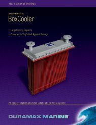
To Download Our Complete Marine Catalog In PDF Format - Newmar
To Download Our Complete Marine Catalog In PDF Format - Newmar
To Download Our Complete Marine Catalog In PDF Format - Newmar

Create successful ePaper yourself
Turn your PDF publications into a flip-book with our unique Google optimized e-Paper software.
shoes • Battery Chargers • DC Converters • <strong>In</strong>verters • Power Supplies • Power Stabilizers • <strong>In</strong>terrs • DC Power Conditioners • Electrical Panels • Meters • Digital <strong>In</strong>struments • <strong>In</strong>stallation Acces09/10
Battery Chargers - Phase Three SeriesThree Stage “Smart” ChargersPhase Three “Smart” battery chargingtechnology is now available in a widerange of power levels, allowing you toselect the right size, features and flexibilityyou require for virtually any applicationfrom small recreational craft tolarge live-aboards, workboats and othercommercial vessels. These chargers interactwith batteries to put them throughthe optimum three stage charge processwhich provides for fastest recovery andideal conditioning, maximizing batteryperformance and extending battery life.A selector switch adjusts output voltage toadapt for gel-cell/flooded lead-acid/AGMbattery types. An optional temperaturecompensation sensor also adjusts outputfor ideal voltage based on changes in thebatteries' ambient temperature. All modelsare housed in a rugged stainless steelcase with a durable white powder coatfinish, and the internal circuitry is polyurethanecoated for maximum corrosionresistance.Features• “Smart” circuitry provides three stage charging—bulk, absorption, float.• Wide model range covers battery system ratings from 14-950 amp-hours• Gel-Cell/Flooded Lead-acid/AGM battery type switch selects optimumcharge/float voltages.• Multiple isolated output banks; ammeter indicates total output current. (except PT-7)• Optional sensor adjusts output voltage based on battery temperature. (except PT-7)• Current limiting-prevents damage from overloading.• Charger status clearly displayed with L.E.D. and/or audible indicators or optionalremote panel.• Use as a power supply; can power loads without a battery in line.• Built to last—rugged stainless steel case with a durable white powder coat finish withan optional drip shield and marinized internal circuitry.• Numerous Safety and EMC Compliances• Two year parts and labor warrantyModels12 Volt 24 Volt 32 VoltPT-7 PT-24-8W PT-32-25WPT-14W PT-24-13WPT-25W PT-24-20WPT-40W PT-24-45UPT-80 PT-24-60WPT-24-95USee next page for detailed specifications.Optional AccessoriesRemote <strong>In</strong>dicator Panel, Model: RP (Not availablefor all models - refer to Specifications onfollowing page)DC Energy Monitor, reads Volts, Amps, AmpHours (See page 20 for details)Temperature Compensation Sensor, Model:TCS-12/24 shown (see next page for applicablesensor depending on charger model)Phase ThreeMonitor/Control UnitFor ABS <strong>In</strong>stallationThis unit, when used in conjunction withcertain PT Chargers* creates a systemwhich is fully compliant with AmericanBureau of Shipping (ABS) BatteryCharging standards for commercialinstallations* For use with all models except PT-7,PT-24-60W, PT-24-95U, and PT-32-25.2 Newport Beach, CA USA<strong>In</strong>corporates• Digital readout of float voltage to1/10th volt• Output float voltage adjustment pot;permits fine tuning from -4% to +5%• AC circuit breaker; provides overcurrent protection and manual disconnect• AC power ON indicator light• 10’ wiring harness for easy connectionof PT Series chargerModel: PT-MCUSize (HxWxD): 8.7”x4.6”x5.5”Weight: 3.5 lbs.DC Power Onboardwww.newmarpower.com • 800-854-3906
Battery Chargers - Phase Three ModularA Battery Charging System withRedundant, Easily Replaced Charge ModulesProviding High Reliability and ServiceabilityReliability• Redundant, independent, charger modules increasereliability – a malfunction of one does not disable thecharging system; remaining modules continueto operate.Serviceability• Module change-out takes only minutes, while thesystem continues to operate• Technical personnel not required• No need to remove the charger case from the boat ordisconnect any wiring• No inconvenience of power interruption to the boatFeatures• Three stage “smart” charging; bulk, absorption, float• Battery type selector switch; gel-cell, lead-acid, AGM• Temperature compensated output option• Numerous diagnostic and system status indicators• 12 Volt; 33-100 amps or 24 Volt; 22-67 amps• “Universal” input of 90-264 VAC, 50-60 Hz.–can beused anywhere in the world• Powder coated stainless steel caseThe Phase Three Modular (PTM) ConceptSuper yachts and commercial vessels have complex electricalsystems that support equipment essential to safe operation.These boats are frequently in transit or in remote locationswhere repair/service is not readily available. Down-time canbe very costly and severely impact sailing schedules.Recognizing that all equipment has a finite service life andrandom component failure can occur at any time, systemreliability can be improved by reducing the number of singlepoints of failure, thus diminishing the impact of a solitaryfault on the overall system. The PTM series applies this “faulttolerant”concept to battery chargers, by using multipleindependent charger modules within the unit.The PTM consists of a case which serves as connection point toAC input and battery bank output, as well as three front-facingpower bays, each accommodating a 550 watt charger modulewhich slides and locks in place. If a module fault occurs, a frontpanel indicator is activated and the system continues operating.Captains and owners will appreciate this system approach to reliability. A dead charger and dead batteries candisable a vessel, but with the PTM redundant charging system a fault in one of the modules is easily identified andit can be quickly replaced with an on-hand spare or an exchange unit from the factory, while the charging systemcontinues to operate.4 Newport Beach, CA USADC Power Onboardwww.newmarpower.com • 800-854-3906
Battery Chargers - Phase Three ModularThe Phase Three Modular (PTM) Series is a battery charging system consisting ofa wall mount case, which serves as a connection point for AC input and batterybank output that accommodate up to three charging modules which slide and lockinto front access power bays. Its redundant charger modules increase reliability, asthe system remains operational in the event of a charger module fault. The systemis easily and quickly restored to full output by simple module replacement.The system features three stage charging for rapid recharge and optimal batterylife. See pages 2 & 3 for a complete description of the three stage charging process.SpecificationsSystem Modules Max Output Max <strong>In</strong>put AmpsModel <strong>In</strong>stalled* Amps @ 115/230 VACPTMS-12-100 3 100 @ 12 V 18/9PTMS-24-67 3 67 @ 24 V 18/9General System Specifications<strong>In</strong>put Voltage/Frequency: 90-264 VAC, 47-63 Hz, single phase; derate linearlyfrom 100% output @ 105 VAC to 80% output @ 90 VACPower Factor: .96-.99Efficiency: 85% typicalNominal Charge/Float Voltages: Refer to chart on page 3Temperature Compensation (Option): - 5 mV per cell per °C (typical)Temperature Rating: 0-60° C; derate linearly from 100% output @ 50° C to 80% output @ 60° CRecommended Battery Type/Capacity: Gel-Cell, Flooded or Sealed Lead-Acid;12 Volt Systems: 6 Cell, 80-400 A-H (per installed module); 240-1200 A-H (per system)24 Volt Systems: 12 Cell, 40-200 A-H (per installed module); 120-600 A-H (per system)Output Battery Banks: 3Module Bays: 3*Status <strong>In</strong>dicators: Output OK, No Output, Check System, Battery <strong>To</strong>o Hot, <strong>To</strong>talOutput Bar Graph, Output Voltage Test Points, Contacts for Optional Remote AlarmCase Material: Powder Coated Stainless SteelCase Size: Refer to diagram at rightWeight: Empty: 16 lbs/7.3 kg. - With three modules installed: 34 lbs/15.5 kg.* Note: Charge modules are shipped in the same carton as the PTM case and are thenplaced in position by the installer.<strong>In</strong>dividual Module SpecificationsModels: PTM -12-33 (12 volt); PTM-24-22 (24 volt)<strong>In</strong>put Voltage/Frequency: 90-264 VAC; 47-63 Hz; derate linearly from 100%output @ 105 VAC to 80% output @ 90 VAC<strong>In</strong>put Current: 3 amps @ 230VAC; 6 amps @ 115 VACPower Factor: .96-.99Efficiency: 85% typicalProtection Features: <strong>In</strong>put Fuse, Output Fuse, Current Limiting, Over VoltageProtection, Cooling Fan, Automatic Thermal Shutdown/RecoveryCompliances:CE Mark, UL Recognized; E183223, Level 3Safety: EN60950-1 USA, Canada, EuropeEMI Radiated and Conducted: FCC Part 15 Level A; EN55022 Class AStatus <strong>In</strong>dicators: Output OK/FAULTWeight: 6 lbs.Output Current:PTM-12-33: 33 amps maxPTM-24-22: 22.5 amps max in Bulk Phase;20 amps max in Absorption/Float PhasesOptionalTemperature Compensation Sensor - Model TCS-12/24: See pages 2 &3 for detailsCase Size<strong>In</strong>chesCentimetersH W D H W D20.9 10.9 8.8 53.1 27.7 22.4Newport Beach, CA USADC Power Onboardwww.newmarpower.com • 800-854-3906 5
<strong>In</strong>verter-ChargersA <strong>Complete</strong> Line of High Power DC-AC <strong>In</strong>verters with Built-in Battery Chargers.The circuitry of these <strong>In</strong>verter/Chargers incorporates a technology which is field-proven and was carefully refined for years in bothharsh industrial and sensitive utility applications. Now this rugged design is offered for marine applications where reliability andperformance are paramount, and low noise operation has become a critical factor in the boat owner’s choice of power products.While incorporating numerous important features these inverter/chargers are engineered with a high functionality approach thatinstallers will appreciate. All connectors and mounts are heavy duty commercial grade.Ten models are available for use with 12, 24 or 32 volt battery systems and provide continuous rated AC power ranging from 1800 to4800 watts at 115 VAC-60 Hz. The dual voltage models are a new addition to the line, ideal for large yachts and commercial vesselswith power requirements for both 115 and 230 VAC equipment.Called the “Perfect Wave” Series,these inverter-chargers deliver pure,sinusoidal* AC for flawless operationof all appliances and sensitiveelectronics. They are ideal forentertainment systems and microprocessor-basedequipment suchas computers which are intolerantto AC wave distortion.* except model 2500IC, whichproduces quasi-sine waveAll models incorporate a built-in automatic transfer switch which activates multi-stage battery charger for rapid andsafe replenishment of the inverter battery bank whenever shore or generator AC power is available.All models feature numerous circuit and safety protections, such as thermally controlled cooling fans, low voltage cutout, thermal andoverload protection and ground fault interruption, and are housed in rugged powder coated aluminum cases suitable for permanenthorizontal or bulkhead mounting. An optional remote indicator and control panel is available for all models.Features• Rugged hostile environment-proven circuitry generates “PerfectWave” AC for powering any appliance, from wattage-hungryrefrigeration to highly input-sensitive computers, electroniccontrollers/processors.• Built-in high output charger for rapid battery bankreplenishment— all models feature three stage, temperaturecompensated charger with output programmable for gel-cell,flooded lead-acid or AGM battery type, and amp-hour capacityselector for proper charging in various applications.• Thermally controlled cooling fan prolongs life of components• Automatic low voltage shutdown circuit prevents damage tobatteries due to over-discharge when using inverter function.• Heavy duty powder coated aluminum construction andpolyurethane coated internal circuitry—built to last in theharsh marine environment.• UL listed with full two year warranty• <strong>In</strong>ternal charger is activated by an automatic transfer relay viaremote sensor whenever external AC power is available.Optional Battery <strong>In</strong>tegrator permits charging of multiple banks(see page 14)• Designed for maximum ease of installation and operation—installer and user-friendly. Large DC input terminal blocks andfront panel GFCI protected outlet receptacles. AC output fromthe inverter may also be hard-wired.• All important aspects of inverter and charger operation clearlydisplayed with front panel status indicators - optional remotepanel available.• Numerous safety and circuit protections: short circuit, overload,over-temperature, ground fault protection, output circuit breaker6 Newport Beach, CA USAOptions/Accessories• Remote control and indicator panel; ICR-2-25 provided with 25‘of cable and ICR-2-50 provided with 50’ of cable.• Duplicates all status indicators found on unit front panel andallows remote ON/OFF capability• Battery <strong>In</strong>tegrator, Models BI-100,BI-200, and BI-24-100, enableschargingof multiple isolatedbattery banks. (See page 14)• AC and DC energy monitors.(See page 20)• <strong>In</strong>verter info center panel blanks.(See opposite page)• High current fuse assembly.(See page 22)Model: ICR-2-25 & ICR-2-50DC Power Onboardwww.newmarpower.com • 800-854-3906
<strong>In</strong>verter-ChargersSpecificationsModel 12-1800IC 12-2500IC 12-3000IC* 12-3000IC-DV*<strong>In</strong>verter Output:VAC 115V, 60 Hz. 115V, 60 Hz. 115V, 60 Hz. 115/230V, 60 Hz.Watts (Surge) 4000 5500 6500 6500Watts (Cont.) 1800 2500 3000 3000Wave Type PS QS PS PS<strong>In</strong>verter <strong>In</strong>put:VDC 11-14 11-14 11-14 11-14Max Amps 180 250 300 300Charger <strong>In</strong>put:VAC 115V, 60 Hz. 115V, 60 Hz. 115V, 60 Hz. 230V, 60 Hz.Max Amps 15 15 20 10Charger Output:Max Amps@V 85A@12V 100A@12V 105A@12V 105A@12VType three stage three stage three stage three stageCase:Size Reference I-2 I-2 I-3 I-3Weight: Lbs./Kg. 54/25 54/25 75/35 80/37Model 24-2200IC 24-4800IC 24-4800IC-DV* 32-2400IC<strong>In</strong>verter Output:VAC 115V, 60 Hz. 115V, 60Hz. 115/230V, 60 Hz. 115V, 60 Hz.Watts (Surge) 6500 14,000 14,000 6500Watts (Cont.) 2200 4800 4800 2400Wave Type PS PS PS PS<strong>In</strong>verter <strong>In</strong>put:VDC 22-28 22-28 22-28 29-38Max Amps 110 240 240 100Charger <strong>In</strong>put:VAC 115V, 60 Hz. 115V, 60 Hz. 230V, 60 Hz. 115V, 60 Hz.Max Amps 15 40 15 15Charger Output:Max Amps@V 40A@24V 105A@24V 105A@24V 30A@32VType three stage three stage three stage three stageCase:Size Reference I-2 I-3 I-3 I-2Weight: Lbs./Kg. 57/26 95/43 80/37 59/27*Special Order Only – Contact FactoryCharger Characteristics:Three stage “smart charger”; programmable via selector switch for gel, flooded lead-acid or AGM battery type; temperaturecompensated. Output voltage temperature compensated via provided battery temp sensor with 20’ cableCase Size References:Case <strong>In</strong>ches CentimetersH W D H W DI-2 7.5 16.0 15.5 19.1 40.6 39.4I-3 10 17 16 25.4 43.2 40.6Wave Type:PS = Pure Sine QS = Quasi SineOperating Temperature (all models):-22˚ C to +40˚ C (0˚ F to 104˚F)<strong>In</strong>verter Regulation: 120 VAC RMS (110V-127V)I-2 & I-3 CaseProtection Features (all models):• Automatic low battery shutdown• Output circuit breaker• Auto high temperature shutdown/recovery• Short circuit protection• Overload protectionMechanical Features (all models):• Thermally controlled cooling fan• Dual GFCI protected duplex outlet• AC hard-wire (optional)• Powder coated aluminum case with shelfor bulkhead mounting flanges• Polyurethane coated printed circuit boardsDC Power OnboardNewport Beach, CA USAwww.newmarpower.com • 800-854-3906 7
Battery Chargers - ABC SeriesABC SeriesThe ABC Series chargers have been in the <strong>Newmar</strong>line for 30 years. They utilize time tested SCR chargingcircuitry, individually sensing and regulating each of2 isolated battery banks, allowing the user to leave thecharger operating indefinitely, even under no-load conditionswithout fear of overcharging. These chargers areideal for vessels or vehicles which have an intermittentdemand for battery power.(For battery systems which require high continuousoutput, see our Phase Three Chargers on pages 2-3)These chargers are housed in a rugged, black anodizedaluminum, heat-sink case which extracts heat withoutintroducing dust and moisture to the inside of the unit.ABC 12-25Features• <strong>To</strong>tal output ammeter• Dual independentlyregulated output banks• On-off switch and power “on”indicator light• Vibration absorbingmounting grommetsABC 12-8• Anodized aluminum case• 115/230 VAC input selectorswitch• Auto-reset thermal breaker• Conformal coating of circuitboardThe rugged and reliable ABC charger is employed inhostile environments throughout the world in recreationand commercial marine applications, off-shoreoil platforms, in mining equipment, emergency servicevehicles and rugged off-road applications.They feature a total output ammeter, on-off powerswitch, power "on" indicator light, 115/230 VAC inputvoltage selector switch, factory installed AC power cordwith molded plug and shock-resistant rubber mountinggrommets. Circuit boards are polyurethane conformalcoated for corrosion resistance and all are protectedagainst overheating by an automatically resettingthermal switch.SpecificationsAmps Output <strong>In</strong>ches Centimeters WeightModel <strong>In</strong>put @ F. L. Volts Banks Amps H W D H W D (Lbs) (Kg)ABC 12-8 105-125 VAC or 1.5/.75 12 2 8 8.0 6.0 4.2 20.3 15.2 10.6 9 4.1210-250 3/1.5 VACABC 12-25 50-60Hz 5/2.5 12 2 25 11.9 4.7 6.2 30.2 11.9 15.8 14 6.4HDWTypical Charge Curves ABC Series% OF CHARGER OUTPUT (AMPS)100% 14.0755025013.012.00BATTERYVOLTAGEAMPSVOLTSTIMECHARGE PHASEFLOAT PHASEDuty Cycle Ratings: Rated Charging Output 20 min., derate to50% for continuous outputOperating Temperature: 0-40°CFloat Voltage: 13.4 VDCUNITMOUNTING SURFACENUTLOCK WASHERFLAT WASHERSPACERSHOCK ISO MOUNTOption: Extreme Vibration Mounting KitThe Extreme Vibration Mounting Kit is available to protect NEWMAR power converters from the extremestresses of shock and vibration when mounted on high–vibration vehicles.The kit (pictured here) replaces the standard vibration kit provided with the unit and fits into the unit'smounting flange to act as a "super shock absorber" for electronics in high-vibe applications. It is availableto fit all NEWMAR units from 2 to 70 lbs. Specify KIT–L for units which weigh 2–15 lbs. and Kit–H for unitswhich weigh 16-70 lbs.8 Newport Beach, CA USADC Power Onboardwww.newmarpower.com • 800-854-3906
DC-DC Converters - Standard & Isolated Series32-12-1532-12-10 Standard SeriesConvert 20-50 VDC to 12 or 24 VDCoutput for powering communication/navigation equipment, on negativeground systems. (See Isolated Series,below for positive ground applications.)Ideal for powering voice, data andnavigation transceivers in mobile andmarine applications.NEW32-12-6Newport Beach, CA USA32-12-5032-12-35 32-12-25<strong>In</strong>put Output Output Amps Case WeightModel voltage voltage <strong>In</strong>termittent Continuous Size (Lbs) (Kg.)Standard Series24-12-3 17-32 13.6 3 3 C-11 1 .4532-12-6 20-50 13.6 6 6 C-10 2.5 .932-24-6 32-50 24.5 6 6 C-10 2.5 .932-12-10 20-50 13.6 10 10 C-2 4 1.832-24-10 32-50 24.5 10 10 C-2 4 1.832-12-15 20-50 13.6 15 15 C-2 5 2.332-24-15 32-50 24.5 15 15 C-2 5 2.332-12-25 20-50 13.6 25 20 C-3 7.5 3.432-24-25 32-50 24.5 25 20 C-3 7.5 3.432-12-35 20-50 13.6 35 30 C-4 12 5.532-24-35 32-50 24.5 35 30 C-4 12 5.532-12-50 20-50 13.6 50 40 C-5 16 7.332-24-50 32-50 24.5 50 40 C-5 16 7.3Isolated Series12-12-12I 10-16* 13.6 12 8 C-8 6 2.712-24-6I 10-16* 24.5 6 4 C-8 6 2.712-12-35I 10-16* 13.6 35 20 C-9 12 5.512-24-18I 10-16* 24.5 18 10 C-9 12 5.548-12-6I 20-56 13.6 6 6 C-7 7 2.748-24-3I 20-56 24.5 3 3 C-7 7 2.748-12-12I 20-56 13.6 12 8 C-8 6 2.748-24-6I 20-56 24.5 6 4 C-8 6 2.748-12-18I 20-56 13.6 18 10 C-8 8 3.648-24-9I 20-56 24.5 9 5 C-8 8 3.648-12-35I 20-56 13.6 35 20 C-9 12 5.548-24-18I 20-56 24.5 18 10 C-9 12 5.5*11.5 VDC minimum start-up voltage, then operates @ 10-16 VDC from 1 amp minimum to full loadPerformance Specifications – Standard & Isolated SeriesOutput: 13.6 VDC (internally adjustable12.6-14.5) or 24.5 VDC (or specify)- except 24-12-3Ripple: 150 mV P-P maximumRegulation: Standard: 1% Line/LoadIsolated: 2% Line/LoadDuty Cycle Ratings*<strong>In</strong>termittent - 20 minutes max on 20%duty. Current limit set at approx. 105% ofintermittent rating*24-12-3: 2 minute max. on timeContinuous - 24 hours, 100% dutyIdle Current: Standard Series: Less than100 mA (including power “ON” light )Isolated Series: approx. 50 mAOperating Temp: 0-50° C,Derate Linearly From 100% @ 40° Cto 50% @ 50° C Thermal shutdown@ 70° C Case TemperatureModel 24-12-3I: Full Output -25° C to +30°C; Derate linearly from 100% @ +30° Cto 45% @ +50° CSwitching Frequency: Standard: 40 KhzIsolated: 70KhzEfficiency: 85% - Typical.Isolation -Output/Chassis: <strong>In</strong>put/Chassis: 250 VDC<strong>In</strong>put/Output: 250 VDC (Isolated Seriesonly)Certification: Carries the CE mark(Standard Series only)• Excellent Regulation: Output voltagemaintained within 1% under all lineand load conditions within rating.• Heat generated by semi-conductors isextracted and dissipated by large heat sinkfins that maximize air contact for cooloperation and long life of components.• Polyurethane conformal coating on PCboards and corrosion-resistant anodizedaluminum case with heavy duty shockmounts assure survival in hostileenvironments.• Numerous converter and load protectioncircuits: Current limiting*; automaticthermal shutdown; short circuit proof*;reverse polarity and overvoltage protection*.* Except 3 Amp. Model.• Carries the CE markIsolated SeriesSame features as Standard Series, but with theadditional capability of permitting connectionof negative ground gear to positive or floatingground battery systems, or vice-versa. Manymodels may also be used as 12 or 24 voltstabilizers for highly input voltage sensitiveequipment (see page 13).<strong>In</strong>put range:10-56 VDC; positive, negative orfloating ground.Output: 12 or 24 VDC, 3 to 35 amps.Options• 24 VDC output (see specs at left)• Operation as battery charger or parallelredundant operation* – derate tocontinuous duty rating (contact factory)• Extreme vibration mounting kit. (See page 10)* Except Model: 24-12-3Case Size<strong>In</strong>ches CentimetersRef. H W D H W DC-1 2.7 4.5 6.0 6.9 11.4 15.2C-2 4.5 5.9 11.0 11.4 15.0 27.9C-3 6.0 4.7 14.0 15.2 11.9 35.6C-4 6.0 4.7 16.0 15.2 11.9 40.6C-5 6.2 6.8 18.1 15.7 17.3 46.0C-7 4.25 5.9 7.7 10.8 15.0 19.6C-8 4.25 5.9 14.0 10.8 15.0 35.6C-9 6.0 6.8 16.5 15.2 17.3 41.9C-10 2.8 4.2 10.4 7.1 10.7 26.4C-11 3.5 3.5 1.75 8.9 8.9 4.5DC Power Onboardwww.newmarpower.com • 800-854-3906 9
Power Supplies - Heavy Duty SeriesSpecificationsNominal Output Amperage Case Size WeightModel <strong>In</strong>put VAC <strong>In</strong>termittent Continuous Ref. Lbs. Kg.12 Volt Output115-12-8 115/230 8 5 P-2 10 4.5115-12-20A 115/230 20 8 P-3 20 9.1115-12-35CD 115/230 35 35 P-5 32 14.624-Volt Output115-24-10 115/230 10 4 P-3 20 9.1115-24-18CD 115/230 18 18 P-5 32 14.6115-24-35CD 115/230 35 35 P-6 60 27.3Case Size<strong>In</strong>chesCentimetersH W D H W DP-2 6.0 4.6 8.5 15.2 11.7 21.6P-3 5.7 4.8 16.3 14.5 12.2 41.4P-5 6.5 9.5 14.0 16.5 24.1 35.6P-6 6.5 13.0 18.75 16.5 33.0 47.6Output Voltage12 V Models:13.6 VDC (<strong>In</strong>ternally adjustable 12.6-14.5 VDC)Ripple: 40mV P-P (@ 110-125/220-250 VAC input)24 V Models:24.5 VDC (<strong>In</strong>ternally adjustable 21-27.5 VDC)Note: When modified for battery charger operation output voltage is factoryset at 27.2 VDCRipple: 70mV P-P (@ 110-125/220-250 VAC input)Regulation All Models: 1% Line and Load (@ 110-125 / 220-250 VAC input)DWHHeavy Duty Series• Designed for powering 12 and 24VDC communication/navigationequipment aboard commercial vesselswhere reliability is the primaryconsideration.• <strong>In</strong>put voltage 115 or 230 VAC selectedby slide switch on the front panel.• Excellent Regulation and RippleSpec: Output voltage maintainedwithin 1% under all line and loadconditions within rating; Ripple isless than 40 mV P-P. (12 volt) or 70mV P-P (24-volt).• Polyurethane conformal coated PCboard and corrosion resistant heavyduty aluminum case with integralshock mounts assures survival inhostile environments.• Heat generated by semi-conductorsis extracted and dissipated by largeheat sink fins that maximize aircontact for cool operation andlong life of components.• Supply and Load Circuit Protection:overvoltage, current limit; (set @105% of intermittent rating), thermaloverload and input/output fusing.• Thermally activated cooling fan on“CD” units.<strong>In</strong>put Range105-125/210-250 VAC (selectable), 50-60 HzDerate to 50% output below 110 and 220 VACOperating TemperatureStandard Units0-50°C, Derate Linearly From 100% @ 40°C<strong>To</strong> 50% @ 50°C Thermal shutdown @ 85°CCase temperatureC.D. Units0-65°C, Derate Linearly From 100% @ 50°C<strong>To</strong> 50% @ 65°C Thermal Shutdown @ 85°CCase temperatureDuty Cycle<strong>In</strong>termittent: 20 minutes max on time,20% dutyContinuous: 24 Hours/Day 100% DutyOptions• Use as a Battery Charger• Output voltage adjust (see Output Voltagefor range)• Transfer relay for back up battery in eventof power failure (ERC option see page 15)UNITMOUNTING SURFACENUTLOCK WASHERFLAT WASHERSPACERSHOCK ISO MOUNT10 Newport Beach, CA USAOption: Extreme Vibration Mounting KitThe Extreme Vibration Mounting Kit is available to protect NEWMAR power converters from the extremestresses of shock and vibration when mounted on high–vibration vehicles.The kit (pictured here) replaces the standard vibration kit provided with the unit and fits into the unit'smounting flange to act as a "super shock absorber" for electronics in high-vibe applications. It is availableto fit all NEWMAR units from 2 to 70 lbs. Specify KIT–L for units which weigh 2–15 lbs. and Kit–H for unitswhich weigh 16-70 lbs.DC Power Onboardwww.newmarpower.com • 800-854-3906
Power Supplies with Built-<strong>In</strong> Battery Back-upPower-PacDesigned for critical applications such as VHF shore stations that must remain on the air, evenduring a power outage. The 12 volt supply features built-in back-up batteries which are chargedduring normal operation and then continue to power radios even when AC power is lost.• Highly regulated, low ripple output for noise-free radio operation• Battery automatically comes on-line if AC fails• Low battery alarm and disconnect, with override switch for emergency powerGeneral Specifications• <strong>In</strong>put 115/230 VAC, 50-60 Hz.• Output:13.6 VDC @ 5A cont., 10A <strong>In</strong>t.• Regulation: 1% line and load• Ripple: 1% P-P• Operating Temp: 0-40° CModels:Power-Pac 7 A/H (w/7 amp/hour battery), 18 lbs.Power-Pac 14 A/H (w/14 amp/hour battery), 24 lbs.Dimensions (both models): 5.3” H x 9.0” W x 10.5” DOptions:• External battery packs available, contact factory for information on BM Series• Also available without batteries installed; contact factory (subtract 15 lbs. from unit weight)<strong>In</strong>tegrated Power SystemPrecision-regulated power supply with built-in batteries, status indicators,alarms and low voltage disconnect. Ideal for GMDSS consoles and basestations. Rear terminals provided to expand back-up capacity by wiringadditional batteries. 19" or 23" rackmount standard. Bulkhead/shelfmounting bracket optional. 115/230 VAC, 50-60 Hz input all models.Model Output <strong>In</strong>ternal Ground Weight Case SizeVDC Amps Battery Reference Lbs Kg. <strong>In</strong>chesContinuous Capacity H x W x DIPS 12-40 13.6 40 16 A-H Negative 32 14.6 3.5 x 17 x 19.5IPS 24-22 27.2 22 8 A-H Negative 32 14.6 3.5 x 17 x 19.5IPS 48-11 54.4 11 4 A-H Positive 32 14.6 3.5 x 17 x 19.5Power Modules & Power Function ManagerPower ModulesPower Modules function as power supply or battery charger; 12, 24or 48 volts; positive, negative floating ground. Wire in parallel tocreate systems from 500-6,000 watts. Optional quick connect wiringkit allows swap-out of modules without system shutdown. 115/230VAC, 50-60 Hz input. 19" or 23" rackmount standard. Bulkhead/shelfmounting bracket optional.Power Function ManagerModel <strong>In</strong>put Amps Output Weight@ F.L. VDC Amps Lbs Kg.115/230V V OUT Cont.+PM-12-40 8.5/4.3 13.6 40 12.2 5.5PM-12-70 16/8 13.6 70 15.2 6.9PM-24-20 8.5/4.3 27.2 20 12.2 5.5PM-24-35 16/8 27.2 35 15.2 6.9PM-24-80 */22 27.2 80 34 15PM-48-10 8.5/4.3 54.4 10 12.2 5.5PM-48-18 16/8 54.4 18 14.0 6.4PM-48-50 */22 54.4 50 34 15+ For parallel configuration/load sharing derate output 10%Newport Beach, CA USAPower Function Manager converts ordinary power supplies(or Power Modules, at left) into a fully integrated and ideallyfunctional complete power system. The unit provides control,monitoring, paralleling and protection of 12, 24 or 48 VDC,positive, negative or floating ground power sources.• Heavy duty (400 amp) input power parallel tie point• Digital output monitoring of system voltage and amperage• System status lights• Five distribution circuit breaker capacity• Auto low voltage or manual battery disconnect• Summary alarm contactsModel: PFM-40019" or 23" rackmount only; 2 RU (3.5") highCase Size - PM and PFM<strong>In</strong>chesCentimetersH W* D H W* D3.5 17 20.5 13.5 43.2 52.1*19” and 23” mounting brackets providedDC Power OnboardHWwww.newmarpower.com • 800-854-3906 11HWDD
DC Power ConditionersStartGuardThe abrupt DC system voltage drop that accompanies enginestarting can cause microprocessor-driven communication andnavigation electronics to “dump” programmed memory.StartGuard solves this problem by providing supplementalvoltage to sensitive electronics while the engine is cranked.It contains a sealed rechargeable battery which is switched onlineto electronics when the starter switch or solenoid is engaged.When the engine is running StartGuard automatically goes offlineand the internal battery is recharged by the alternator.Specifications<strong>In</strong>put Voltage: 13.8 - 14.8 VDC nominal, 15.5 VDC max.Relay Activation <strong>In</strong>put Voltage: 7-15 VDCOutput: 20 amps max.Battery: 12 VDC, sealed rechargeable,5 - 7 year life (typical)5 amp-hour capacityCertified by DOT and IATA for shipment by airReplacement battery P/N: 591-0412-0Back-up Capacity (Fully Charged): (See matrix below)DC INPUTPROBLEMS HEREVOLTAGE DIPSCAUSED BYENGINE STARTINGNO PROBLEMS HEREModel <strong>In</strong>put Back-Up Capacity Dimensions Weight1 Minute 2 Minutes <strong>In</strong>ches Centimeters Lbs Kg.NS-12-20 13.8-14.8 VDC Nominal 20 amps 15 amps 8.25 x 4.9 x 3.5 20.1 x 12.5 x 8.9 5.5 2.515.5 VDC MaxU.S. PATENT #: 5172292NAV-PAC ®<strong>Marine</strong> communication/navigation electronics such as programmabledata transceivers, GPS and other microprocessor-controlleddevices require clean and steady DC input power. Their sensitivecircuitry is highly vulnerable to voltage drop from engine start,noise and line spikes from alternators and motors, and conductednoise from various other electronic devices. NAV-PAC preventsthese conditions from affecting electronics.Model: NP-12<strong>In</strong>put Voltage: 13.8-14.8 VDC nominal, 15.5 VDC max.Output: 20 amps Max. @ 12 VoltBack-Up Power:7 Amps for fifteen (15) minutes10 Amps for eight (8) minutes15 Amps for two (2) minutes20 Amps for one (1) minuteBattery: Sealed Rechargeable 5.0 Amp-Hour, 5-7 yearstypical life, can be replaced. Low-voltage disconnect circuitprotects battery from total discharge. Certified by DOT and IATAfor shipment by air. Replacement battery P/N: 591-0412-0Noise Filtering: Audio through 200 MHZVoltage Spike Protection:Transient energy capability; 100 Joules, 4,000 amps Max(8 x 20 micro seconds)Size ( H x W x D): Weight5.25" x 6.2" x 7.4" 5.9 lbs.,13.3 x 15.7 x 18.8 cm 2.7 Kg.,Panel Dimensions: 3.5” W x 2” H (8.9 x 5.1 cm)RADIO• Prevents voltage ”drop-out” to electronics during engine start• Absorbs line "spikes"• Filters out electrical interference• Provides supplemental voltage/battery back-up for up to 15 min.• Remote monitor panel included.12 Newport Beach, CA USADC Power OnboardD.G.P.S.DATA TRANSCEIVERwww.newmarpower.com • 800-854-3906
NEWDC Power StabilizersNEW12-12-3112-12-12INEW24-24-7I12 & 24 Volt Stabilizing ConvertersFeed sensitive electronics with proper voltage regardless of batterycondition. These stabilizing converters provide continuous, preciselyregulated output over the entire range of a battery's usable voltage. Thisprevents subjecting loads to fluctuating input voltage which can causeshutdown, diminish performance and possibly damage sensitive circuitry.<strong>In</strong>put16 VDC10 VDC12 Volt SystemOutput13.6 VDC<strong>In</strong>put30 VDC20 VDCApplication Benefits <strong>In</strong>clude:12 Volt System 24 Volt System• Operate electronics at optimal input voltage, even from nearly<strong>In</strong>putdrained batteries• Boost voltage to compensate for voltage 16 VDC drops in long wire runs<strong>In</strong>put30 VDCfrom batteriesOutput• Eliminate voltage drops during momentary high current drain from13.6 VDCbatteries, as during engine start 10 VDC20 VDC• Eliminate voltage fluctuation from charge sources• Eliminate voltage overshoot due to sudden removal of high current loadThese converters provide total input/output isolation, virtually eliminatingconducted line noise and permitting connection of negative ground gear topositive or floating ground systems, or vice versa. They can also be modifiedfor use as battery chargers, allowing them to maintain a battery at a greatdistance from the primary voltage source, providing reserve power if themain source fails. The rugged anodized aluminum case is ideal for marineapplicationsOptions/Factory Modifications• Operation as a battery charger(contact factory)• Parallel/redundant operation(contact factory)• High vibration mounting kit(see bottom of page 10)• Non-standard output voltage(contact factory)Output24.5 VDC<strong>In</strong>put Output Output Amps Case WeightModel voltage voltage <strong>In</strong>termittent Size (Lbs) (Kg.)12-12-3I 10-16 13.6 3 C-4 1 .4512-12-6I 10-16 13.6 6 C-4 1 .4512-12-12I 10-16* 13.6 12 C-2 6 2.712-12-35I 10-16* 13.6 35 C-3 12 5.524-24-3I 20-56 24.5 3 C-3 12 5.524-24-7I 20-32 24.5 7 C-5 2 .948-24-6I 20-56 24.5 6 C-2 6 2.748-24-9I 20-56 24.5 9 C-2 8 3.648-24-18I 20-56 24.5 18 C-3 12 5.5*11.5 VDC minimum start-up voltage, then operates @ 10-16 VDC from 1 amp minimum tofull loadSee page 9, Isolated Series Converters for complete specifications andmechanical description.Case Size<strong>In</strong>ches CentimetersRef. H W D H W DC-1 4.25 5.9 7.7 10.8 15.0 19.6C-2 4.25 5.9 14.0 10.8 15.0 35.6C-3 6.0 6.8 16.5 15.2 17.3 41.9C-4 3.5 3.5 1.75 8.9 8.9 4.5C-5 7.0 3.5 1.75 17.8 8.9 4.5Newport Beach, CA USADC Power Onboardwww.newmarpower.com • 800-854-3906 13
Battery Isolators & <strong>In</strong>tegratorsBattery IsolatorsThese heavy duty isolators allow charging multiple batteries automatically from one or twoalternators, and prevent discharge or 'dumping” of one battery into another. Each battery ischarged according to its need without overcharging. Rated for 12-48 volt negative groundDC systems. Feature conservatively rated diodes and a rustproof anodized aluminum heatsink case. Models are available for 70, 120 and 165 amp alternators.Model Alternator Battery Max Amperage Weight DimensionsSources Bank <strong>In</strong>put Capacity Lbs Kg L W H1-2-70 1 2 70 2 .9 3.25 4.5 3.1 in8.3 11.4 7.9 cm1-3-70 1 3 70 2 .9 3.25 4.5 3.1 in8.3 11.4 7.9 cm2-3-70 2 3 70 4 1.8 6.5 4.5 3.1 in16.5 11.4 7.9 cm1-2-120 1 2 120 3 1.4 6.5 4.5 3.1 in16.5 11.4 8.0 cm1-3-120 1 3 120 3 1.4 6.5 4.5 3.1 in16.5 11.4 8.0 cm2-3-120 2 3 120 5 2.3 12.5 4.5 3.1 in30.5 11.4 7.9 cm1-3-165 1 3 165 5 2.3 9 4.5 3.1 in22.9 11.4 8.0 cmApplication Note: Battery Isolators may also be used to facilitate N+1 parallel/redundantoperation of power supplies. Contact factory.Features:• Heavy duty construction• Rated for systems up to 48 volts DC,negative ground• Rust-proof anodized aluminum case• Stainless steel mounting hardware provided• Protective covers provided for terminalsPerformance SpecificationsOperating temperature: -40 to +80° CDuty cycle: Continuous rating to 50° CDerate linearly to 70% @ 80° CTemp. rise: 95° C at full rated current (mountvertically for optimum cooling)Voltage drop: 0.7V @ 50% load0.9V @ full loadNote: These battery isolators are not compatiblewith self exciting alternators. Please consultthe manufacturer of your alternator if youare unsure of your configuration.Battery<strong>In</strong>tegratorChargingmultiple batterybanks withoutuse of diodeisolators dictatesthat the batteriesbe connected or“integrated” onlywhenever a chargevoltage is present so that theymay be charged simultaneously,then disconnected or “isolated” when in useto allow for selective discharge and avoidhaving the secondary or standby batterydrain into the primary battery.Battery <strong>In</strong>tegrators perform this functionautomatically, acting as a “smart” switchto connect independent battery banksonly when a charging voltage is present.Otherwise, they are isolated, anddischarge between banks is prevented.Features• Enables charging of two separate bankswithout voltage drop, yet maintains100% isolation at all other times.For systems of three banks or more, anadditional unit must be installed foreach additional bank• Heavy duty silver-plated contactor,continuous duty rated• Voltage sense circuit, epoxy encapsulatedand heavy duty continuous ratedsolenoid are all designed for use inmarine environments• 12 volt model has ignition protectionrating• Easy three-wire hook up for two banksystems (BATT +, BATT +, GROUND)• Terminal for optional wiring of remotelight indicating when battery banks areintegrated• Optional internal connection can bewired though key starter or manual override switch, tying battery banks togetherfor extra boost during engine startSpecificationsModels: BI-100; BI-200; BI-24-100Battery <strong>In</strong>tegration Connect Point:13.2 VDC (approx.)26.4 VDC (approx.)Battery Disconnect Point:12.8 VDC (approx.)25.6 VDC (approx.)Maximum Continuous Current:100 amps (100 amp models)200 amps (200 amp model)Peak Maximum Current:400 amps (100 amp models)600 amps (200 amp model)Operating Temperature:Control: -40 to +85˚ CSolenoid: -28 to +48˚ CTerminals: Battery Connections:5/16" copper alloy studDimensions (H x W x D):3" x 3.25" x 2.5"Weight: 1 lb.APS-7014 Newport Beach, CA USAAutomatic Power SelectorThe Automatic Power Selector (APS) is a solid state device which enables installation of a seamless,redundant power system for critical electronic loads. It selects the higher voltage of two isolated DC powersources and routes power to the load. Should one source falter or fail, the other will automatically supplythe load with no transfer delay, operation continues uninterrupted.Easy installation, two independent power sources are wiredto the APS and routed in a single output to the vital load.Rugged, rust-proof anodized aluminum case.Models:APS-70 Max. Load 70 amps,, 3.25" x 4.5" x 3.1", 2 lbs..APS-160 Max. Load 160 amps, 9.0" x 4.5" x 3.1", 5 lbs.Voltage Rating: 6-50 VDC, neg. groundBattery orPower Supply 1Battery orPower Supply 2Critical ElectronicsTypical<strong>In</strong>stallationDC Power Onboardwww.newmarpower.com • 800-854-3906
DC Power AccessoriesLow Voltage Disconnect - LVDDischarging batteries beyond a criticallow voltage can damage the batteriesand/or load, and require a longerrecharge interval. A low voltagedisconnect prevents this condition.Emergency Relay/Charger - ERCThe E.R.C. allows emergency battery tie-into a radio system that is normally operatedby a power supply.Lamp Dimmer SystemAdjust DC lights to ease eye strain andenhance night vision. Light intensity iseasily regulated by remote panel.The LVD contains a sense and controlcircuit housed in a compact, rugged,vinyl-clad aluminum case. It is installedin-line between the battery and the load.The unit continually monitors batteryvoltage and if it falls below a preset voltagethreshold, the load is automaticallydisconnected. When batteries arerecharged past another pre-set voltagethe load is reconnected. Connect anddisconnect points are user adjustable.Models:LVD 12-30, LVD 12-75 (Neg. Ground)LVD 24-50 (Neg. Ground)LVD 48-30 (Pos. Ground)SpecificationsFactory Set Actuation Voltages:Disconnect 10.4 VDC 21.0 VDC 42.0VDCLVDConnect 12.2 VDC 24.5 VDC 49.0VDCChargingLoadSourceVoltage and Contact Current Ratings:(i.e., Battery LVD 12-30 = 12 Volts, 30 AmpsContinuous)ChargingSource12 VOLT 24 VOLT 48 VOLT<strong>In</strong>dicated By Model NumberDimensions (Mounted vertically, allmodels): 5.25” H x 5.25” W x 3.5” DWeight: (All models): 1 LB.Typical LVD <strong>In</strong>stallationLVDRadioUnder normal conditions the radio isconnected through the ERC to the powersupply and the back-up battery receivesonly a trickle charge to keep it in peakcondition.<strong>In</strong> the event of AC power failure a relayautomatically connects the radio to theback-up battery, restoring the system withinone second. When AC power is restoredthe radio is automatically reconnected tothe power supply and the trickle chargeresumes to the battery.Available in 12 or 24 VDC, 15 or 35 Ampratings, (not ignition protected.)Application notes:• 1 sec. switch over delay may not besuitable for data transceivers, use insteada system where the battery is floated onoutput of power supply – see Power-Pacor IPS (pg 11) or APS (pg 14).• Trickle charge current will maintain aback up battery and will slowly restore adeeply discharged battery. A separatehigh current charging source is recommendedfor deep discharge recovery.SpecificationsERC Amps Size-inches Lbs KgModel <strong>In</strong>t. Cont. H W D12-15 15 10 2.25 2.875 4 1 .524-15 15 10 2.25 2.875 4 1 .512-35 35 30 3.875 2.875 4 2 .924-35* 35 30 3.875 2.875 4 2 .9*Built to orderTypical Trickle Charge Current:1.5 amps – will vary depending on powersupply voltage and battery condition.Optimal Power Supply Voltage:12 volt systems: 13.4 - 14.0 VDC24 volt systems: 26.8 - 28.0 VDC+Battery–Typical ERC <strong>In</strong>stallation(optional)+– –+ ERC +–12 VDC–+RadioControl Panel - LDP5000 Ohm dimmer control panel adjustsbrightness between Off and 85% of fullvoltage. Black anodized aluminum panel.Size: 3" x 3" (7.6 x 7.6 cm)Dimmer Unit - LD100 watt capacity, for 12, 24, and 32 VDCsystems. Rugged anodized aluminum heatsink case.Size: 9" x 4.5" x 2.75"; 2 lbs.22.9 x 11.4 x 7cm. .9 Kg.Model: LD PanelControl PanelModel: LDDimmer only (no panel)LAMP DIMMERLOWTypical LD <strong>In</strong>stallationHIGHCONTROLLAMPSRTN10-36BatteryNewport Beach, CA USA+PowerSupply–DC POWERSOURCEDC Power Onboardwww.newmarpower.com • 800-854-3906 15
Electrical Panels – Elite SeriesES-1 DC Master PanelThis DC master control panel offers a large DC circuit capacity and full metering.Features:• Analog DC volt and ammeter, back illuminated with dimmer.• 4 battery bank test switch.• DC master breaker (100 Amp standard; 50 or 75 amp optional)• 22 branch circuit capacity, 20 installed standard; 3-5A, 5-10A, 6-15A, 6-20A or specify• Red circuit "on" indicator lights.• LS-III Label set included.• Multiple position ground Bus Bar included.• Size: 10"W x 15"H x 4" D, (25.4 X 38.1 X 10.2 CM), Weight 8 lbs., (3.6 Kg.)ES-1Because of their exact height match and style compatibility, the panels below are ideal companions for expanding circuit capacityof the ES-1 or ES-5, or they may be used as stand-alone load centers.ES-6 DC Load CenterFeatures:• Accommodates one meter; analogstandard. (DC 0-50A ammeter standard),or specify DC volts• Master breaker (DC-75 amp standard; 50or 100 amp optional, single pole)• 10 branch circuit capacity,8 installed standard:1-5A, 2-10A, 4-15A, 1-20A• <strong>In</strong>dicator lights on every circuit.• LS-III set included.• Multiple position ground Bus Barincluded.• Size: 5 1/4" W x 15" H x 4" D,(13.3 x 38.1 x 10.2 cm)ES-7 AC or DC Accessory PanelFeatures:• AC or DC master breaker (AC 50amp* standard, 30 amp optional,double pole or DC 100 amp standard;50 or 75 amp optional, single pole.)• 16 branch circuit capacity,12installed standard:ES-7A: 2-10A, 5-15A, 5-20AES-7D: 2-5A, 3-10A, 5-15A, 2-20A• <strong>In</strong>dicator lights on every circuit.• LS-III label set included.• Multiple position groundBus Bar included.• Size: 5 1/4" W x 15" H x 4" D,(13.3 x 38.1 x 10.2 cm)Weight: 7 lbs., (3.2 Kg.)ES-6* Note 50 amp master OK for use on230 VAC line-to-line systems. For 230VAC line-to-neutral systems 30 amp ismaximum master breaker value.ES-7OptionsMeters:Standard installed voltmeters arefor 12 VDC or 115 VAC applications.(Ammeter range depends onmaster breaker value.) Optionalvoltmeters may be installed for24 VDC or 230 VAC applications.Contact the factory for a completelist of metering optionsAlternate Circuit BreakerConfigurations:Changing circuit breaker valuemix or location is never a problem!Simply advise us of the breakerarrangement you need. (Panelspecific illustrated order formslisting all options are available atwww.newmarpower.com.) Pleaseallow 3-5 days additional lead timeto complete the modification.Note: There is a mod. fee for specialconfigurations – contact factory.<strong>In</strong>stallation Cut-Out DimensionsModel <strong>In</strong>ches Centimeters(H x W) (H x W)ES-1 9 X 14 22.9 X 35.6ES-3 13 X 8.8 33 X 22.4ES-4 16.8 X 10.8 42.7 X 27.4ES-5 19 X 13 48.3 X 33ES-6D 4.5 X 13 11.4 X 33ES-7A & 7D 4 X 13.8 10.2 X 35.116 Newport Beach, CA USADC Power Onboardwww.newmarpower.com • 800-854-3906
Electrical Panels – Elite SeriesAC-DC Master ControlLocating all AC and DC functions on one panel provides a vesselwith a central load distribution and monitoring center. Featurescommon to all models include:• <strong>Complete</strong> metering of voltage and current on AC andDC systems. Back-lit analog meters are standard.• AC master breaker(s) with reverse polarity warning light.• Power "on" indicator lights on all circuits.• Four battery bank voltage test switch• Deluxe label set (LS-III) included, 206 functions.• Multiple position ground bus bar• Rating 115/230 VAC, 65 VDCES-3This panel combines AC and DC control into one compactpanel. See list of specifications at bottom of page.13.7" W X 10” H X 4” D, 10 lbs(34.8 X 25.4 X 10.2 cm, 4.5Kg.)ES-3ES-4Large 3 1/2" scale meters and an ample circuit breakercapacity makes this the panel of choice for boats in the35'-45' range. Circuit specifications listed at bottom of page.17” W X 12” H X 4” D, 12 lbs (43.2 X 30.5 X 10.2 cm 5.5 Kg.)ES-5Exceptional yachts require an extraordinary panel whichincorporates all the aspects of the vessel's electrical system.The ES-5 is such a panel. <strong>In</strong> addition to its large DC circuitcapacity, the AC section includes two load groups and asource selector switch for two shore power lines and a 15kWgenerator. Pre-heat and start-stop controls are standard.Additional system capacity can be obtained byincorporating model ES-6 or ES-7 (listed on page 16).20" W x 15" H x 6" D, 20 Lbs.(50.8 X 38.1 X 15.2 cm, 9.1Kg.)ES-5ES-4OptionFor vessels with an onboard generator,the panel may be fitted with a 7.5 kWship-shore AC source selector switch.Specify ES-4SS option when ordering.Note: There is a modification fee for special configurations- contact factory.Model DC Circuits AC CircuitsES-3 16 Breaker capacity, 12 <strong>In</strong>stalled standard; Master (D.P.) 30 amp standard 50 amp* optional, plus 6 S.P. branch2-5A, 3-10A, 4-15A, 3-20A or specifycapacity, 5 installed standard; 1-10A, 15A, 2-20A or specifyES-4 20 Breaker capacity, 16 <strong>In</strong>stalled standard; Master (D.P.) 50 amp* standard plus 8S.P. branch capacity,3-5A, 3-10A, 5-15A, 5-20A or specify6 installed standard; 1-10A, 3-15A, 2-20A or specifyES-4SS Same as above with 7.5 kW, three position (Shore-Off-Gen) ship shore selector switch installed. Special Order Only.ES-5 Master plus 24 breaker capacity, 20 installed standard; Two load groups each consisting of: Master breaker (D.P.) 50 amp*3-5A, 4-10A, 7-15A, 6-20A or specifystandard plus 10 S.P. branch capacity, 8 installed standard;2-10A, 3-15A, 3-20A or specify*Note (For panels used in 230 VAC applications): 50 amp Master OK for use on 230 VAC line-to-line systems. Not for 230 VAC line-to-neutral systems.Newport Beach, CA USADC Power Onboardwww.newmarpower.com • 800-854-3906 17
Electrical PanelsNEWMAR offers a wide range of stylishly engineered electricalpanels to provide control, protection and monitoring for onboardelectrical circuits, ranging from basic meter panels tofull-function AC/DC master distribution centers.The panels are manufactured with 1/8" strong black anodizedaluminum, feature elegant graphics, and their modular designallows integration of multiple units for a "custom" installation. Allpanels are pre-wired with bus bars and ground strips for easyinstallation, and come with extensive circuit identification labelsets. The circuit breakers use a "trip-free" magnetic-hydraulicmechanism and are UL recognized and CSA listed.<strong>In</strong>dividual circuit "ON" indicator lights are now standard for alldistribution branch circuit breakers. Many models of meterpanels and distribution panels are also available as blanks withbus bar, breaker mounting screws, labels and indicator lightmounting hardware, allowing the installer to select from a widearray of components for maximum options in electricalsystem design.Accessory PanelsThese versatile panels are ideal for smaller vessels with only a limited number of electrical circuits, or for larger systems where theirmodular design makes for an easy and attractive expansion of existing system capacity.Stock panels with breakers installed come standard with DC indicator lights, but may be factory modified with AC indicator lightsinstead. Blank versions of the panels come with all necessary hardware to install lights and breakers. All panels are provided witha circuit identification label set of 22 common on-board electrical functions (see below).ACCY-IX: 8 breaker capacity, 5 installed standard; 2-5A,1-10A, 1-15A, 1-20A or specify. 8 DC circuit "ON" indicatorlights installed standard, AC lights optional. Size: 7 1/2" x 51/4", Weight: 2 lbs.ACCY-IBX: Blank version of ACCY-IX above. No breakersprovided. Label set, light and breaker mounting hardwareprovided. Weight: 1 lb.ACCY-IIX: Half-height version of ACCY-IX at left. 3 breakercapacity, 3 installed standard; 3 DC “ON” indicator lightsinstalled standard - AC optional. 1-5A, 1-10A 1-15A orspecify. Size: 3 3/4" x 5 1/4", Weight: 1 lb.ACCY-IIBX: Blank version of ACCY-IIX above. No breakersor lights provided. Label set, light and breaker mountinghardware provided. Weight: 1 lb.See page 22 for PanelBack Enclosures.Typical Accessory Panel Wiring DiagramFromPowerSource+ DC or AC Hot- DC or AC Neutral<strong>In</strong>stallation Cut-Out Dimensions*<strong>In</strong>ches (W x H) Centimeters (W x H)ACCY-IX 4 X 6 10.2 X 15.2ACCY-IBX 4 X 6 10.2 X 15.2ACCY-IIX 4 X 2.5 10.2 X 6.4ACCY-IIBX 4 X 2.5 10.2 X 6.4* Allow approximately 3” depth clearance for all panels on this page.<strong>To</strong> Load(Typical)+ DC or AC Hot- DC or AC NeutralLabel Set ProvidedEach panel is provided with a basic set of the followingfunctions listed. Other more extensive label sets (up to206 functions) are also available separately. <strong>To</strong> see thecomplete list, visit www.newmarpower.com and click onElectrical Panel Accessories.SafetyGroundRed Light: 12 or 24 VDCAmber Light: 115 or 230 VACLS-I Standard Set 22 LabelsACCESSORYAFT CABINANCHORBILGE PUMPBOWCABIN LIGHTSENGINE ROOMFORE CABINMAIN CABINMASTNAV/COMOUTLETSREFRIGERATORRUNNINGSPARESPREADERSUMP PUMPWATER HEATERWATER PRESSUREWINDLASSWINDSHIELD18 Newport Beach, CA USADC Power Onboardwww.newmarpower.com • 800-854-3906
Electrical PanelsDC Master PanelDC monitor, protection, and control. Dimensional compatibility allows easyexpansion of the system by incorporating additional accessory or monitorpanels (see pages 18 and 21, respectively). Features an illuminated, expandedscale DC voltmeter with dual battery bank test switch and individual “ON”indicator lights. A label set of common on-board circuits is provided(see page 18, LS-I, for label list).DC-IIX: Voltmeter with dual battery bank test switch; 11 circuit breakercapacity, 9 installed standard 2-5A, 3-10A, 4-15A or specify.Panel size: 10 1/2" x 7 1/2", (26.7 X 19 cm.); Weight: 4 lbs., (1.8Kg.)<strong>In</strong>stallation Cut-Out Dimensions<strong>In</strong>ches CentimetersDC-IIX 8.3 X 6.3 21.1 X 16AC Master PanelsEssential control/protection whenever AC from shorepower or generators is on board. A double pole master breaker with power onindicator light protects both hot and neutral legs of the AC circuit. A reverse polarity light provides clear warning when wiring isreversed and poses a shock hazard. Single pole branch circuit breakers (Model AC-IX) and individual “ON” indicator lights providecontrol and protection of various AC loads. For 115/230 VAC applications – see ratings note. A label set of common on-board circuitsis provided (see page 18, LS-I, for label list).AC-IX: 30 amp master breaker (15A or 50 A* optional),5 branch circuit capacity 4 installed standard1-10A, 2-15A, 1-20A, or specify. LS-I Label setincluded. Panel size: 5 1/4" x 7 1/2", (13.3 X 9.5 cm.,)Weight: 2 lbs., (.9 Kg.)See pg 23 forAC SourceSelector Switch.AC-II: 30 Amp master breaker (15A or 50A* optional).Panel size: 5 1/4" x 3 3/4" (13.3 X 9.5 cm.),Weight: 1 lb (.5 Kg.)*50A option rating note: OK for use on 230 VACline-to-line systems. Not rated for 230 VACline-to-neutral systems.Typical AC Panel Wiring DiagramShore PowerConnectoror ACSourceSelectorSwitchGround(Green)Neutral(White)SafetyGroundACMasterBreaker<strong>In</strong>stallation Cut-OutDimensions<strong>In</strong>chesCentimetersHot(Black)AC-IX 4 X 6 10.2 X 15.2AC-II 4 X 2.5 10.2 X 6.4<strong>To</strong> AC Load(Typical)GroundNeutralHotAlternate Circuit Breaker Amperage RatingsChanging circuit breaker value mix or location for any panel shown onthese pages is no problem! Simply advise us of the breaker arrangementyou need. (Panel specific illustrated order forms listing all options areavailable at www.newmarpower.com.) Please allow 3-5 days additionallead time to complete the modification. Note: There is a modification feefor special configurations – contact factory.Newport Beach, CA USADC Power Onboardwww.newmarpower.com • 800-854-3906 19
Digital <strong>In</strong>struments for AC/DC SystemsThese highly versatile and sleekly designed digital instrumentsprovide comprehensive monitoring of onboard AC and DCelectrical systems. They give quick, accurate, up-to-the momentinformation on all important aspects of electrical system status– voltage, current, power consumed, power available, ACfrequency, abnormal system conditions, and more.All read-outs and programming of these multiple functions areeasily controlled via touch-pads on the instrument face. LCDdisplays are easily read in bright sunlight and feature five leveladjustable red back-lighting for conservation of night vision.High/low voltage and frequency alarms are standard, and DCmonitors are NMEA 0183 compatible. Typical accuracy is +/- 1%.These instruments are waterproof and are suitable for installationin exposed above deck areas, such as open cockpits andflybridges (provided there is no water ingress to the rear of themounting surface). The meter/touch-pad and surrounding bezelare fully waterproof and the ABS housing is UV stabilized.All models are designed for through-bulkhead mounting; 2 1/2”models may also be installed in NEWMAR’s Single Universal Seriespanel (see page 21).All instruments are pre-calibrated for typical use settings at thefactory prior to shipment, however they may be recalibrated viatouch pad after installation to suit the special needs or conditionsof any particular vessel.DCEACEDCVDCE: DC Energy MonitorDisplays volts, amps, energy used and remaining for12 or 24 volt systems up to 500 amps and up to 3,000amp-hour capacity. Makes DC energy managementa breeze. Monitor voltage on up to three separatebanks. House bank (or battery bank of choice) maybe also be programmed for the following functions:1) Monitor charge/discharge amperage. 2) <strong>To</strong>talenergy monitor can be set for amp-hours or percentof-charge.3) High/low voltage alarm, plus alarmset-point for low amp-hours remaining. 500 ampshunt included. NMEA 0183 compatible output fordata logging. Available in 2 1/2” or 4 1/4”square face.ACE: AC Energy MonitorFor 115/230 volt systems. Reads: 90-300 VAC (TrueRMS), 0-150 amps, frequency from 40-70 Hz andpower from 0-45 kW. Features alarm circuits forhigh/low voltage and high/low frequency. Canbe programmed to provide automatic generatorshutdown (see Remote Alarm Option below) in theevent that voltage or frequency exceedpredetermined range. Current and voltagetransformers are included. 12 or 24 volt sourcerequired to power meter. Available in 2 1/2” or4 1/4” square face.DCV: DC VoltmeterFor three battery banks, 12 and/or 24 volt systems.Reads to the nearest 1/10 volt. Features aprogrammable high/low voltage alarm circuitfor each bank. NMEA 0183 compatible for PCinterface. Only available in 2 1/2” version.<strong>In</strong>strument Drawings & Mounting Options2 1/2” model depicted: Large Scale <strong>In</strong>struments useidentical size mounting hole and hardware configuration2 3/8"2 1/8" (55mm) HoleAvailablein 2 SizesAvailablein 2 SizesDCE-VAH-110Large Scale Models Now Available<strong>Our</strong> DCE and ACE Digital <strong>In</strong>struments are nowoffered in a large LCD read-out design. Digits arean easy-to-read 1 1/4” tall, allowing monitoringfrom a distance. Large button keypads makeprogramming and function selection a breeze!All instrument ratings and functions are identicalto standard scale instruments described at left.Mounting hole requirements and hardware are alsoidentical to standard scale models. <strong>In</strong>strument facedimensions: 4 1/4” x 4 1/4” (110 mm x 110 mm)ModelsDCE-VAH-110 Large scale version of DCE shown at leftACE-VAF-110 Large scale version of ACE shown at leftRemote Alarm Relay OptionAll instruments shown on thispage have programmablealarms. A relay is now availablethat activates from the instrumentalarm signal output terminalallowing remote activation and/or connection to the vessel’s 12or 24 volt alarm panel.3 5/8"Threaded StudMay Be Cut DownIf Necessary <strong>To</strong>Minimize RearProjectionBulkhead GasketSingle And Dual<strong>In</strong>strument PanelBlanks Available(Opposite Page)Model:DIR Digital <strong>In</strong>strument Relay<strong>In</strong>put Signal: 5 VDCRelay Rating: 12/24 VDC, 10ampsSize: 2.4” x 1.4” x 1.5”Model: DIR20 Newport Beach, CA USADC Power Onboardwww.newmarpower.com • 800-854-3906
MeteringAssemble an electrical monitoring system using these meters and the panel blanks shown below. Meters are now available in Digitaland Analog format in 2 1/2” and 3 1/2” sizes. One pre-fab meter panel accommodates the 2 1/2” meters and digital instruments (seepage 20).Analog MetersEasy to read graphics with unit divisionsgive precise readouts at a glance.Designed for easy front or rear panelmounting. See below for meter panelblanks.AC MetersAC Volt 0-150AC Volt 0-300AC Amp 0-50 w/current transformerAC Amp 0-100 w/current transformerDC MetersDC Volt 8-16DC Volt 16-32DC Amp 0-50 w/shuntDC Amp 0-100 w/shuntReplacement Shunts/Current Transformers For Analog Meters• Shunt for 0-50 DC ammeter• Shunt for 0-100 DC ammeter• Current transformer for 0-50 AC ammeter• Current transformer for 0-100 AC ammeterMeter Face Measurements3.5” scale: 3 3/4" W x 2 7/8"H (9.5 X 7.3 cm)2.5” scale: 2.1/2" W x 2 3/8"H (6.3 X 6.0 cm)Meter Panel BlanksUniversal SeriesMPB-SU: Single Universal Panel; accommodates one 2 1/2"meter or one Digital <strong>In</strong>strument in front-mount configuration;can be oriented for either horizontal or vertical mounting.Panel dimensions: 3 3/4" x 5 1/4"DC Power OnboardNewport Beach, CA USAwww.newmarpower.com • 800-854-3906 21
Electrical Panel AccessoriesCircuit BreakersAll circuit breakers offered by NEWMAR are UL recognized and CSA listed for ACand DC systems and meet USCG requirements as a qualified circuit protection device.Standard Series: Single and Double PoleFit all NEWMAR electrical panels, as well as most other brands• Feature magnetic-hydraulic “trip-free” mechanism• 5-30 amp rated to 65 VDC or 277 VAC; 40 and 50 amp rated to 32 VDC or 120 VAC(See rating note below).• Mounting screws not provided order separately• #10 screw terminals on rear for wiringOptions• Red, white or black toggle handles• Single pole values: 5, 10, 15, 20, 25, 30, 40 or 50 amp.• Double pole values: 15, 20, 30 or 50 ampImportant Circuit Breaker Rating Note: Standard series breakers shown on this pagewhich are rated higher than 30 amps are acceptable for use in 230 VAC Line-to-Linesystems (where each leg is 115 VAC - to - neutral), but are not rated for 230 VACline-to-neutral systems.#6-32M3.610"15.49mm1.66042.16mm.590"14.99mmDIA.2"50.80mmDouble PoleNote:Square cut-out mounting configuration fits EliteSeries Panel (manufactured 1995 or later) DCmaster breaker position only.– 1/4” studs on rear for wiring– Two 6-32 screws required for mounting;not included w/bulk pack – order separately– Auxiliary alarm contacts (form C)22 Newport Beach, CA USAHigh Amperage Series: Single PoleRated for up to 65 VDC or 120/240 VAC service• Feature auxiliary contacts for optional remotemonitoring of circuit breaker status• “Trip-free” mechanismOptions• Current rating of 75 or 100 amps• Black or white toggle1.438"36.53mm.750" Max.19.05mmLabel SetsIdeal for custom labeling of switch or circuit breaker positions onany NEWMAR or similarly constructed electrical panel. Whitelettering on black peel-and-stick mylar. Label size: 1.75" W x .5" HModels:LS-I Standard Set - 22 labelsLS-II Electronic Set - 55 labelsLS-III Deluxe Set - 206 labels(Visit www.newmarpower.comfor a complete list of Label Sets)Panel Back EnclosuresSecure to the rear of many common electrical panels to protectcrew against injury or panel against damage from accidentalcontact. Heavy duty ABS plastic. May be cut or drilled to suitwiring needs. (<strong>In</strong>termediate mounting surface between paneland enclosure required)Model Size (H x W x D) Fits these NEWMAR PanelsBE-432 4.5" x 3.2" x 2" ACCY-IIX, AC-II, METER-IIBE-855 8" x 5" x 5" ACCY-IX, AC-IXBE-1085 10" x 8" x 5" DC-II"mm".0102.060".2552.32mm• Heavy duty 500 amp, insulated, .010 compact fuse block with2.060.25corrosion-resistant 5/16” studs1.43836.53.750 Max.19.0510.21.75"19.18mmMAX.5.59DC Power Onboard52.32.170" 4.32mmSingle Pole1.515"38.48mmMAXHigh Current Fuses/FuseblocksEssential safety item for all inverterinstallations and other highamperage DC circuit over-currentprotection.• Secures to surface with two #10 flat head screws or bolts(not included)• Clear lexan cover insulates conductive parts,per ABYC/USCG requirements• Accepts industry standard ANL tin-plated copper fuses.Purchase separately.• See-through mica element for easy identification of blown fuseFuseblock Model: AFB-500Fuse Models (numeral indicates amperage): ANL-50, ANL-100,ANL-150, ANL-200, ANL-250, ANL-300, ANL-350, ANL-400,ANL-500 (All rated to 80 VDC)<strong>In</strong>dicator LightsUse as "circuit on" or serviceindicator light on AC or DCsystems. Snap-in panelmount in 5/16" hole, 6",18 AWG leads.Models:115/230 VAC Amber*115/230 VAC Red115/230 VAC Green12/24 VDC Red*12/24 VDC Green* standard replacement lightfor <strong>Newmar</strong> panels availablein skin pack or bulk packwww.newmarpower.com • 800-854-3906
AC Source SwitchesSS-7.5 INVSS-3.0An AC source selector switch is an essential item for any boat with an onboard AC generator and/or inverter. The switcheliminates the safety hazard and/or damage that can occur if two AC sources are applied to the same circuit simultaneously.These switches are fitted with a compact escutcheon plate with engraved switch position nomenclature (mountingdimensions below).The switches carry UL and CSA approval, are CE marked, and feature heavy duty contacts and a positive step cam mechanismfor low resistance contact closure. May be installed in panel with thickness up to 1/4”.Standard SwitchesModel Amperage Number Switch Positions Standard Plate@ 115/230 of Poles Markings**SS-3.0 30 2 2 + “OFF” SHIP-OFF-SHORESS-7.5 63 2 2 + “OFF” SHIP-OFF-SHORESS-7.5 INV† 63 2 3 + “OFF” OFF-GEN-INV-SHORESS-15* 126 2 2 + “OFF” SHIP-OFF-SHORE*May be configured as a 63 amp, 4 pole switch† For vessels with onboard generator and inverterMounting Flange DimensionsAll standard switches, plus 63 and 80amp special order switches. 100 and 125amp special order switches only.Special Order SwitchesIf none of the standard switches listed above meet your requirements, NEWMAR will customconfigure an AC selector switch for you. Please allow 2 weeks for shipment. Contact factoryfor pricing..472"2.52".59"3.46".216"1) Determine the following:A) Amperage/kW rating requiredB) Number of switch positions requiredC) Number of poles required2) Use the chart below to determine model number:Amperage/kw Rating 2 Position Plus Off 3 Position Plus Off 4 Position Plus Off@ 120 VAC 2 Pole 3 Pole 2 Pole 3 Pole 2 Pole 3 Pole63 Amp (7.5 kw) S-622 S-632 S-623 S-633 S-624 S-63480 Amp (10 kw) S-822 S-832 S-823 S-833 S-824 S-834100 Amp (12.5 kw) S-1022 S-1032 S-1023 S-1033 S-1024 S-1034125 Amp (15.5 kw) S-1222 S-1232 S-1223 S-1233 S-1224 S-1234.196"1.89"2.67"Depth DimensionsSS-3.0 2 1/8”SS-7.5 2 3/8”SS-7.5 INV 3 1/2”SS-15 4”3) Select the desired switch selector position labeling from the following list:SHORE GEN PORT SHORE PORT GENSHORE 1 GEN 1 STBD SHORE STBD GENSHORE 2 GEN 2 INVor specify the position labeling you require.If you have need for a specific arrangement of the switchselector position labels, please mention this at the time of ordering.Note: Combination switches similar to one used in our ES-5panel, (see page 17) also available. Contact factory formore information.Newport Beach, CA USADC Power Onboardwww.newmarpower.com • 800-854-3906 23
AC Shore Power AccessoriesGI-100Galvanic IsolatorSacrificial zincs corrode away as they protect metalthru hulls, shafts and props from damaging electrolysis.Stray, low voltage current flowing between theAC safety ground and DC bonding system is aprincipal cause of this "galvanic" action.<strong>In</strong>stalling the Galvanic Isolator between the ACsafety ground and DC bonding system (seediagram), blocks a majority of the low voltagecurrents and corrosive action on the zincs issignificantly reduced (while the integrity of thecritical safety ground path is maintained.) Thismeans a significant savings in boat haul-out feesand zinc replacement costs.For additional safety, all units feature a large capacitor,providing a secondary low impedance path forsending AC current to ground.Three models are offered; rated for 30 amp, 50 ampor 100 amp shorepower.Model SHORE POWER Shore Power Dimensions WeightVAC, Hz Rating, Amps H W D Lb. Kg.GI-30 115/230, 50-60 30 2.7 4.8 7.3 in. 2.45 1.16.9 12.2 18.5 cm.GI-50 115/230, 50-60 50 4.5 4.7 8.9 in. 3.2 1.511.4 11.9 22.6 cm.GI-100* 115/230, 50-60 100 15 7.25 7.2 in. 13.35 638.1 18.4 18.2 cm.Typical WiringSHORE SIDEBOAT SIDEGROUNDINGCONDUCTOR(GREEN)NEWMARGALVANICISOLATOR*(BLACK)(WHITE)(GREEN)GI-50GI-30SHORE POWERCABLECONNECTORPOWER INLETELECTRICALLYINSOLATED FROMTHE BOATMAIN SHOREPOWERDISCONNECTCIRCUITBREAKER*Special order item.Allow 2-3 weeks for deliveryTO ENGINE NEGATIVE TERMINAL(BOAT GROUND)AC PanelsThese panels provide essential control and protection for shoreand on-board AC sources. Two pole breakers with singletoggle provide maximum protection with easy fingertipdisconnect. All models feature a reverse polarity warning.light to provide clear indication when hot/neutral wiring isreversed and presents a shock hazard. Master and branchcircuit breakers have power "ON" indicator lights. For 115or 230 VAC applications.AC-IX: 30 amp double pole master breaker (15A or 50A optional)plus 5 single pole branch capacity, 4 installed standard; 1-10A,2-15A, 1-20A. Master and branchcircuit "ON" and reverse polaritywarning indicator lights installed.Label set of 22 commonshipboard circuits provided.Size: 7.5" x 5.25", Weight: 2 lbs.AC-II: 30 amp double pole master breaker only (15A or 50Aoptional). Master AC circuit "ON" and reverse polarity warningindicator lights installed. Size: 3.75" x 5.25", Weight: 1 lb.AC SourceSelector Switches*50A option rating note:OK for use on 230 VACline-to-line systems.Not rated for 230 VACline-to-neutral systems.Wide range of sizes and styles available. See page 23.24 Newport Beach, CA USADC Power Onboardwww.newmarpower.com • 800-854-3906
Terminal Strips & Bus BarsTerminal Strips• Use as a common negative/neutral bus for AC or DCsystems. Dual terminal strips in 4 or 8 screw positions on3/4” centers are secured to a high density insulatedbase. All hardware, bus material and fasteners arenickel-plated brass.• #8 screws accommodate various size ring terminals andeach terminal strip is rated for 100 amps.• <strong>In</strong>terlocking bases allow use of multiple terminal stripsand bus bars (described below) to produce secure andneat wiring assemblies. The terminal strip bases haveprovisions for either #8 or #10 mounting screws, and noconductive parts in the base are exposed to themounting surface.• A clear plastic insulating cover is provided with skinpacked units, Specify bulk or skin pack when ordering.TS-2x4TS-2x8Model <strong>To</strong>tal # of Base Terminals SizeTS-2x4 8 3 1/16” x 1 1/2”TS-2x8 16 6 1/16” x 1 1/2”<strong>In</strong>terlockingFeatureBB-2BB-5BB-2/8Model Qty. of 5/16” Studs Base SizeBB-2 2 3 1/16” x 1 1/2”BB-2/8 2 plus 8 - #8 screws 6 1/16” x 1 1/2”BB-5 5 6 1/16”” x 1 1/2”BB-8 8 9 1/16”” x 1 1/2”BB-8<strong>In</strong>terlocking FeatureBus Bars• Ideal as a DC ground tie point orpositive bus, these heavy duty, 500amp rated bus bar assemblies feature5/16” studs on 1” centers in 1/4” thickcopper bar for common connection/distribution of large wire gauges andaccommodate 5/16” ring terminals.• One combination model features two5/16” studs and eight #8 screws,accommodating multiple sizewire terminals.• All bus material is nickel-plated copper.• A clear insulating protective cover isprovided to prevent short circuits andprovide visibility of lugs.• The mounting bases are keyed forinterlocking and may be mated withthe terminal strips (described above).Conductive parts are captured andrecessed away from the mountingsurface. Use #8 or #10 screws for mounting.Connector Strips• Molded nylon encases 6 or 12 pairs of connectors that use screw compressionto secure wires without use of lugs. Ideal for electronic installations. Brassbarrels capture wires and are held in place with a stainless steel “finger”compressed by a screw. The screw does not make contact with the wires,protecting the copper strands from cuts and breakage – Meets ABYCstandards. (Same connector strip used in BX Series boxes – see page 26.)• 3 Sizes: ranging from 6 to 16 gauge• Strips are easily cut to meet wiring requirements and space limitations.• All models clamshell packed for attractive retail display, or bulk packedfor contractor use.# of Max Wire Max SizeModel Terminal Pairs Gauge Amps* L X W X HCS-1 12 16 6 3.75” x .675” x .5”CS-2 12 14 10 4.5” x .75” x .75”CS-3 12 12 16 5.5” x .875” x .8”*Per set of terminalsCS-1CS-2Newport Beach, CA USADC Power Onboardwww.newmarpower.com • 800-854-3906 25
Thru-Dex ® – Waterproof BoxesPX-3PX-2PX-1Waterproof Junction BoxesPX Series• Ideal for making wiring connections above or below decks, even in areassubject to occasional spray• Similar to BX Series junction boxes, but made from rugged, non-corrosive,high impact polypropylene• Snap-on cover provides watertight seal• “Universal” cut-to -fit (see diagram) graduated diameter cable entriesaccommodate wide cable range• Multiple position connector strips with “captive” screw compression wireterminals installed – meets ABYC standards (same type as CS-1, page 25)• Multiple knockouts provided for conduit access (in addition to cable entries)• IEC Waterproof Rating: IP54 – “Water projected in jets against the enclosurefrom any direction shall have no harmful effects.”Graduated Diameter,Flexible Cut-to-fit Cable EntriesModel PX-1 PX-2 PX-3Number of Connector Strips 1 2 2Positions per Strip 6 6 9Max Wire Gauge 16 16 16Number of Cable Entry Ports 5 7 7Number of Cable Entries <strong>In</strong>stalled 3 7 7Spare Cable Entries Provided 2 0 0Cable Diameter Range (inches) .14-.81 .14-.81 .14-.99Cable Diameter Range (mm) 3.5-20.5 3.5-20.5 3.5-25.5Box Size (inches) 2.95 x 2.95 x 1.66 3.35 x 3.35 x 1.66 4.45 x 4.45 x 2.29Box Size (cm) 7.5 x 7.5 x 4.2 8.5 x 8.5 x 4.2 11.3 x 11.3 x 5.8Splashproof Junction BoxesBX-2BX-3BX Series• Provides for secure, protected below-deckwiring connections, IP rating 54• Rugged cast aluminum box with whiteenamel finish• Easy wiring access through multiplegrommeted cable entries• Supplied with high quality connector strips- secure wires w/compression fittings – noterminals required (See CS-1and CS-2,on opposite page for full description – seematrix below for number/gaugeof terminals)BX-1Model BX-1 BX-2 BX-3Number of Connector Strips 1 1 2Positions per Strip 6 12 11Max Wire Gauge 16 16 14Max amps (Per Position) 6 6 10Cable Entries 2 8 2Max Cable Diameter .25” .37” .59Box Size (inches) 2 x 2 x 1.2 4.4 x 2.4 x 1.2 4.7 x 3.7 x 1.3Box Size (cm) 5.1 x 5.1 x 3.1 11.2 x 6.1 x 3.1 11.9 x 9.4 x 3.326 Newport Beach, CA USADC Power Onboardwww.newmarpower.com • 800-854-3906
Electrical Enclosures, Cable EntriesEX Series Electrical EnclosuresThese enclosures provide functional and professional protective cases for wireconnectors, terminal blocks, relays, solenoids, fuses, etc. The corrosion-resistantpolycarbonate cases are ideal for marine applications, and the deep cavitydesign leaves room for securing wiring and components and making connections.<strong>In</strong> addition, instruments, switches and panels can be surface mountedto the cover, as there is ample space for rear projection and wiring.EX-474EX-1074The enclosures have gasketed covers with captured non-corrosive securingscrews and offer various levels of water resistant integrity per installeroption, depending on type of cable entry used (see below). Waterproof entriesprovide IP68 protection while the splash-proof entries are rated at IP54. TwoSplash-proof entries are (model SPF-1) included with the enclosures.EX-373Enclosure mounting points are located in the bottom of the box and caps for waterproofsealing of the mounting holes are provided. Also supplied is an internal base plate withstand-off mounts for securing components inside the enclosure.Knock-outs in numerous sizes are positioned on all four sides of the enclosures, givingthe installer many options on cable entry type and location for convenient, professionalwiring. (See choices of Cable Entries below.)Application example - EX-474 shown withdigital instruments mounted in coverEnclosure Size L x W x D Knock-Outs (size cross-reference below)Model(inches)EX-373 7.09 x 3.7 x 3.19 14 ea. PG-16EX-474 7.09 x 4.33 x 4.37 16 ea. PG-16, 4 ea. PG-21, 2 ea. PG-29EX-1074 7.09 x 10.0 x 4.37 24 ea. PG-16, 8 ea. PG-21, 4 ea. PG-29Cable EntriesChoose from waterproof or splash-proof enclosurecable entries in various sizes.Waterproof FittingsFor complete waterproof assembly (IP68) use these compressionfittings. Retaining nut secures fitting to enclosers, compressionhub creates waterproof seal around wires. Various sizes areavailable in a wide range of cable diameters.WPF-3WPF-2WPF-1Model Cable Diameter Mounting Hole EX EnclosureRange Diameter Knock-Out Size Ref.WPF-1 .2”-.47” .91” (22.5 mm) PG-16WPF-2 .35”-.71” 1.14” (29.0 mm) PG-21WPF-3 .55”-.98” 1.48” (37.5 mm) PG-29Splash-Proof FittingsFlexible fittings snap into access holes on enclosures.Graduated diameter, cut-to-fit sizing accommodatesa wide range of cable diameters. Can also functionas a splash-proof plug on knocked-out enclosureaccess hole. Sold in pairs.SPF-2SPF-1Graduated Diameter,Flexible Cut-to-fitCable EntriesModel Cable Diameter Mounting Hole EX EnclosureRange Diameter Knock-Out Size Ref.SPF-1 .14”-.81” .91” (22.5 mm) PG-16SPF-2 .14”-.99” 1.14” (29.0 mm) PG-21Newport Beach, CA USADC Power Onboardwww.newmarpower.com • 800-854-3906 27
Antenna/Cable AccessoriesWaterproof Fittings• Create a 100% waterproof seal when routing cables through decksand bulkhead• Allow installation and/or removal of cable with connector still attached• Accommodate wide range of cables• Rugged, weatherproof glass-filled nylon• Available in two series:DX Series – Drill holes and slit cablegland as required to accommodatecable with or without factoryinstalledconnector. Multiple cablesmay be passed through asingle fitting.CCX Series – Entry hole pre-drilled in seal with slit to edge allowingfeed thru of cable with factory-installed connector attached; multipleglands cover a wide range of cable sizes; one CCX fitting required foreach cable.Model Cable Max TypicalDiameter Connector ConnectorRange DiameterCCX-R .47"-.59" 1.57" Large Radar PlugCCX-S .35"-.55" .83" Small Radar PlugsCCX-T .18"-.35” .83" PL-259, BNC, Wind <strong>In</strong>strument PlugsModel Drill Thru Max.ApertureConnector Dia.DX-2 1.18" Diameter 1.18”DX-3 1.57" Diameter 1.57”DX-5* 1.9" Diameter 1.9”* Aluminum HousingRailFast ® Antenna MountsQuick, easy installation of antenna on 1" or 7/8" railing. Ideal for G.P.S., VHF radio,and whip antennas, has direct feed-thru hole for coax cable. Ratchet surface permits360° rotation for adjustment/lay-down. Holds antennas up to 8' (2.4 meters) in length.No drilling required; all necessary hardware provided. (US Patent #4546949)311-N• Model 311-NStrong, fiberglass filled nylon rail mount for permanent antenna installation withhex-key vertical adjustment. Smooth spherical shape won't catch lines or clothing.• Model 311-NLHSimilar to 311-N (listed above), but has lay-down handle that permits quick, easylay-down of antenna.311-NLHAntenna/Coax SwitchesManualModel: CS-201Two position switch allowsmanual selection of one oftwo antennas with a singleradio or one of 2 radios witha single antenna. Die castaluminum case.Power: 1.5 kW peak1 kW continuousImpedance: 50 ohmConnectors: S0-239/UHFWeight: 1Lb., .5 Kg.RemoteModel: RCSOperates on 12 VDC,single pole, double throw.Permits remote selectionof two antennas with asingle radio.Power: 1 Kw.Impedance: 48 ohmCoil Current: 250 mAConnectors: SO-239/UHFWeight: 1 Lb., .5 Kg.28 Newport Beach, CA USADC Power Onboardwww.newmarpower.com • 800-854-3906
Grounding & Noise FiltersCopper Strap & Copper Screen SizesModel Width Length WeightGS-2-25 2” 25’ 3 lbs.5.1 cm 8 meters 1.4 kgGS-2-50 2” 50’ 5 lbs.5.1 cm 17 meters 2.3 kgGS-2-100 2” 100’ 8 lbs.5.1 cm 33 meters 3.6 kgGS-4-100 4” 100’ 16 lbs.10.2 cm 33 meters 7.3 kgScreen-25 4’ 25’ 16 lbs1.2 meters 8 meters 7.3 kg.Copper Strap• Ideal conductor for RF grounding of SSB radios and othernoise sensitive transceivers or for bonding of thru-hulls, etc.• Flexible – easily conforms to vessel contours• .01” (25mm) thick – see matrix for available lengths and widthsCopper Screen• Tight copper mesh (.05” x .01” wire spacing) ideal forcreating a ground plane in hull. Length: 25’; Width: 4’• May be placed into electronics enclosures to provide anRF barrier.Ground Shoes• Provide an excellent noise-free RF ground by making directcontact with water outside hull.• Porous copper construction magnifies contact area – see matrixfor surface area equivalent• Silicon bronze hardware provided (Not intended for lightningprotection)Model Dimensions Ground Area Weight<strong>In</strong>ches Centimeters Equivalent Lbs Kg8A 8 x 2 .5 x .5 20.3 x 6.3 x 1.3 20 sq. ft. 6.1 M 2 3 1.412C 12 x 3 x .5 30.5 x 7.6 x 1.3 40 sq. ft. 12.2 M 2 4 1.818E 18 x 6 x .5 45.7 x 15.2 x 1.3 100 sq. ft. 30.5 M 2 11 5Noise FiltersThe interference or electronic “noise” generated by alternators,ignition systems, motors, etc., can render a vehicle or vessel’s radioor other electronic equipment virtually useless. This interferencetakes the form of popping or static on radios or audio gear andgarbled images or “hash” on video displays.These specialized filters can be used singly or in combination toattenuate conducted line noise, either at the affected equipmentor at the noise source.Model Rating <strong>In</strong>stallation Size WeightLocation H W D150-A 150 Amp <strong>In</strong> the alternator 3.25” 5.75” 3.25” 3 lbs.output lead (8.2 14.6 8.2cm 1.4Kg.)PC-10 10 Amp <strong>In</strong> the + and - 1.25” 4.25” 3” 1 lb.power leads (3.2 10.8 8.2cm .5Kg.)close to affectedequipmentPC-25 25 Amp Same as PC-10 2” 4.25” 3.25” 2 lbs.(5.1 10.8 8.2cm .9 Kg.)Filter Features:• Heavy duty aluminum construction• Operate on 6-48 VDC systems• <strong>In</strong>tegral mounting flanges for secure installation• Brass stud connectors on alternator filtersaccommodate high current cables and terminals• Color coded wire leads on all other models makein-line installation easyFiltered Frequencies• Model 150A: 70 kHz – 100 MHz• Models PC-10 and PC-25: Audio – 200 MHzNewport Beach, CA USADC Power Onboardwww.newmarpower.com • 800-854-3906 29
Test EquipmentDigital Battery AnalyzerThe Digital Battery Analyzer (model DBA) is an essential tool for all DC system installers, techniciansand battery dealers. Simple to use, it performs a complete analysis of battery condition in mereseconds, then displays conclusive data on a large clear LCD readout.The DBA analyzes 12 and 6 volt lead-acid, gel-cell and AGM batteries of all types with ratings from100-1400 CCA. It provides information on battery voltage, battery condition and available batterypower. This gives you empirical data to assure your customers that their batteries are fine, or tosupport your recommendation that they be replaced.The unit is housed in rugged ABS plastic, yet is light-weight and compact for use in cramped batterycompartments and portability in tool kits. It comes equipped with 32” polarity color-coded test leadsand quick-connect clamps. The DBA indicates whether the clamps have proper contact withbattery posts.Single-battery banks or batteries connected singly in series may be tested without disconnection.Parallel batteries must be disconnected prior to testing.No internal battery nor external AC power source is required. Clear and concise operatinginstructions are provided.Features:• Analyzes 12 volt and 6 volt lead-acid batteries of all types: flooded, gel-cell or AGM; deep-cycle or gen/engine start• Simple three step test procedure provides a comprehensive analysis of batteries in seconds. (See <strong>In</strong>set.)• No need to recharge batteries prior to testing; accurate results for batteries in any state of charge down to 5.5 volts• Uses sophisticated conductance technology; will not harm or discharge batteries• Rugged, compact, light-weight case; easy to use even in hard-to-access battery compartments• Temperature compensation setting when testing batteries below 32˚F (0˚C)• Handy water-resistant carry-case with shoulder strap providedSpecifications:Model: DBA - Digital Battery AnalyzerBattery Type: 12 or 6 VDC nominal, lead-acid (flooded, gel or AGM),deep-cycle or gen/engine startBattery Capacity: 100-1400 CCA (Cold Cranking Amps)Operating Range: 5.5 - 14.0 VDC<strong>In</strong>put Power: Operates on power of battery under test, down to 5.5 VDCDisplay Type: LCDTemp. Range: 32-120˚F (0-50˚C); temperature compensation providedbelow 32˚FProtection: Will not be harmed by accidental reverse polarity connectionCase Material: Acid resistant ABS plasticSize: 9" x 4" x 2.5"Weight: .9 lb., .4 kg.Warranty: Two YearsSimple Testing Procedure1. Clip DBA leads to battery terminals2. Using touch pad, select battery CCA rating fromdisplay menu3. Press start test button.<strong>In</strong> less than a minute, the unit analyzes then displays:1. Battery voltage2. Available power (in CCA)3. One of the following battery condition readouts:GOOD BATTERYGOOD-RECHARGECHARGE & RETESTREPLACE BATTERYBAD CELL-REPLACE BATTERYElectrical System AnalyzerAn essential tool for any marine electrical system installer or surveyor, the ElectricalSystem Analyzer provides extremely accurate data on all major AC and DCelectrical functions in a convenient hand-held device with large easy-to-readLCD display.Measures and Displays:• AC Voltage up to 400 VAC• AC Current up to 200 Amps• Frequency at 50-100,000 Hz• DC Voltage up to 400 VDC• DC Current up to 200 Amps• Electrical ContinuityFeatures:• Clamping sensor allows current measurement withoutdisconnecting wiring or shunt installation• Long easy-grip color coded needle-type test probes• Operates on two AA batteries (provided)• Protective carry-case included30 Newport Beach, CA USAModel: ESADC Power Onboardwww.newmarpower.com • 800-854-3906
Phone-Com SystemsPI-10The Phone-Com intercomsystem provides direct, wired,point-to-point communicationanywhere on the vessel. Voicecontact to any phone in thesystem is as easy as lifting thereceiver and pressing the callbutton. Phone-Com operates on12 VDC. They are constructed ofhigh-impact plastic and are availablein either bright white or traditionalblack. Bulkhead mountingbracket is provided. Two versionsare available:PI-2: Designed for communicationbetween only two points. A single call buttonsounds a buzzer and illuminates an indicator lampon the companion phone. Available singly or as a set with 40' ofinterconnect wire, fuse, terminal lugs and mounting hardware.PI-10: For multiple station calling capability. Up to 10 phonesmay be interconnected, and each phone has 10 call buttons.Sold individually-- see wiring requirements below.Phone-Com Wiring: Color-coded multi-conductor interconnectwire (22 AWG) is available from NEWMAR at any lengthdesired with 5, 10 or 15 conductors. For PI-2, use 5 conductorwire. For PI-10, add 3 to the total number of stations todetermine minimum number of conductors required.Note: Phones are not waterproof and should be installed in aprotected location.PI-2: Two station phone with single call button; sold individually;2 lbs.PI-2 SET: Two station phoneset, 40' interconnect wire,fuse, lugs, mounting hardware;5 lbs.PI-2PI-10: Multi-station phonewith 10 call buttons, soldindividually; 2 lbs.22 AWG Wire: 5, 10 or 15conductor; sold per foot.BUZZER: External buzzer foruse in high-noise areas, 1 lb.(Specify White or Blackwhen ordering)PI-10AQ Series Waterproof Radio CoversAQ-10L/RHand-held radios can be takenanywhere without being damagedby water, dust or sand when theAQ Series waterproof cover is usedfor protection. Even total immersionwill not harm the radio. Thesecovers are certified waterproof to adepth of 33 feet.The case is made of super-tough,UV resistant PVC, which is engineeredwith enough flexibility tofacilitate easy operation of knobsand keypads. Transparent designallows easy reading of digitaldisplays. Sound is virtuallyunimpeded and RF transmissionis unaffected.A quick release clip allows easy insertionand removal of the radio and ahandy lanyard provides extra securitywhen hands are wet. But if the radiofalls into deep water, no problem! Safelyinside the AQ case, it will float!Weight (all models): 1 lb.ModelsAQ-10L/R For compact hand-held radios.New reversible design accommodatesboth left and right hand antennas;Replaces AQ-10AQ-20L/R For standard size hand-helds.New reversible design accommodatesboth left and right hand antennas;Replaces AQ-20L and AQ-20RAQ-2MXL Larger and longer than AQ-20 for high power radios with largebattery packsDeck Horns/HailersDimensions ininchesA=Overall heightof radio/phonewith antennaextendedB= Height ofradio/phonebodyC=Combinedwidth and depthof radio/phonebodyModel A B CAQ-20L/R 15.7" 7.8" 5"AQ-2MXL 21.2" 10.6" 5.3"AQ-10L/R 13" 6.1" 4.1"Clear, distortion free, waterproof deck horns are ideal for shipboard paging, hailing, fog horn andalarm systems. High impact plastic with hook-up wire provided. 8 Ohm. Assembled with stainlesssteel hardware.CBAPA-60/40Heavy DutyCommercialNewport Beach, CA USAModel Output Nominal/Peak WeightPA-8W 8 watts / 12 watts 1 lb.PA-30/20 30 watts / 20 watts 3 lbs.PA-40/30 40 watts / 30 watts 5 lbs.PA-60/40 60 watts / 40 watts 8 lbs.Note: Model PA-60/40 is a commercial grade horn whichalso features excellent sensitivity as a microphone for usein talk-back systems.PA-40/20PA-8WPA-30/20DC Power Onboardwww.newmarpower.com • 800-854-3906 31
www.newmarpower.comABC Chargers 8AC/DC Monitors 20-21AC Source Switches 23Ammeters 20-21ANL Fuses 22Antenna Mounts 28Antenna Switches 28AQ Series Waterproof Covers 31Automatic Power Selector 14Battery Analyzer 30Battery Chargers 2-5, 8Battery <strong>In</strong>tegrators 14Battery Isolators 14Bus Bars 25Cable Fittings/Feed-Thrus 27-28Circuit Breakers 22Clamshell Fittings 28Coax Switches 28Connector Strips 25Copper Strap 29DC-DC Converters 9, 13DC Power Conditioners 12-13DC Voltage Stabilizers 13Deck Fittings 28Deck Horns 31Digital Battery Analyzer 30Digital <strong>In</strong>struments 20Dimmer, Lighting 15Distribution Panels 16-19, 24Enclosures, Panel 22Electrical Panels 16-19, 24Electrical System Analyzer 30Electronic Filters 29Emergency Relay/Charger 15Feed-Thru Fittings 27-28Fuses, Fuseblocks 22Galvanic Isolators 24Ground Shoes 29Ground Strap 29Hailer Horns 31<strong>In</strong>dicator Lights 22<strong>In</strong>struments, Digital 20<strong>In</strong>tegrated Power Systems 11<strong>In</strong>verter-Chargers 6-7<strong>In</strong>tercoms 31Junction Boxes 26-27Label Sets 22Lamp Dimmer 15Low Voltage Disconnects 15Meters, AC/DC 20-21Meter Panels 21Microphone Clips 28NAV-PAC 12Noise Filters 29Paging Speakers 31Panel Blanks 18-19, 21Panel Enclosures 22Phase Three Chargers 2-3Phase Three Modular Chargers 4-5Phone <strong>In</strong>tercoms 31Power Conditioners 12-13Power Function Manager 11Power Modules 11Power-Pac 11Power Supply, Bench 11Power Supplies, Heavy Duty 10Power Supplies with Battery 11Railfast Antenna Mounts 28Ship-Shore Switches 23Speakers, Paging 31StartGuard 12Terminal Strips 25Voltage Stabilizers 13Voltmeters 20-21Waterproof Fittings 27-28Waterproof Junction Boxes 26-27Waterproof Radio Covers 31Waterproof Speakers 31Distributed By:P.O. Box 1306 Newport Beach, CA 92663 • 2911 West Garry Avenue, Santa Ana, CA 92704Phone: 714-751-0488 • Fax: 714-957-1621 • E-Mail: sales@newmarpower.comndlato