NCB shaft liner installation-guide - Marine Office
NCB shaft liner installation-guide - Marine Office
NCB shaft liner installation-guide - Marine Office

Create successful ePaper yourself
Turn your PDF publications into a flip-book with our unique Google optimized e-Paper software.
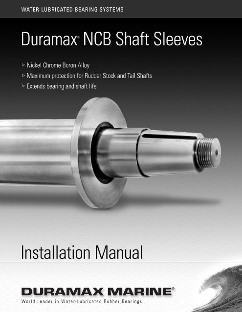
WATER-LUBRICATED BEARING SYSTEMSDuramax®<strong>NCB</strong> Shaft Sleeves Nickel Chrome Boron Alloy Maximum protection for Rudder Stock and Tail Shafts Extends bearing and <strong>shaft</strong> lifeInstallation ManualWorld Leader in Water-Lubricated Rubber Bearings
IntroductionInstallation of Duramax ® <strong>NCB</strong>Rudder Stock & Tail Shaft SleevesDURAMAX ® <strong>NCB</strong> HARDCOATINGRESISTS ABRASION AND CORROSION,EXTENDING SHAFT-ASSEMBLY LIFE:DURAMAX ® <strong>NCB</strong> (Nickel-Chrome-Boron) SHAFT SLEEVESare guaranteed to double the life of conventional materialssuch as 316 or heat treated 410 stainless and will actuallygive 4-5 times increased wear life. The 58 to 62 Rockwell “C”hardness rating of the DURAMAX ® <strong>NCB</strong> (Nickel-Chrome-Boron) SHAFT SLEEVE increases service wear life of <strong>shaft</strong>sand <strong>shaft</strong> sleeves where mechanical abrasion and corrosiontake place (example – seal, packing, and bearing areas.)The fused area of the <strong>shaft</strong> sleeve is undercut .065 to .070inches per side. The undercut area is then thermal coatedwith the Nickel-Chrome-Boron (<strong>NCB</strong>) powder. Usingmultiple spraying passes, the sleeve is hard-coated to anoversize dimension. A heat treating process is used tofuse or metallurgically bond the <strong>NCB</strong> hard coating tothe base metal at around 2000°F. After cooling, the <strong>shaft</strong>sleeve is ground to a 6-8 RMS finish and provides a58-62 Rockwell “C” hardness.DURAMAX ® SHAFT SLEEVEOPTIONAL BORE DIMENSIONS:Duramax ® <strong>NCB</strong> Shaft Sleeves are supplied with either“FINISHED BORE” or “ROUGH BORE” inside diameters.FINISHED BORE:Duramax ® <strong>NCB</strong> Shaft Sleeves with “FINISHED BORE”dimensions are supplied ready for shrink-fit <strong>installation</strong> onthe <strong>shaft</strong> and do not require machining of the sleeve borediameter prior to <strong>installation</strong>. Duramax ® <strong>NCB</strong> Shaft Sleevesordered with “FINISHED BORE” dimensions require thecustomer to provide <strong>shaft</strong> diameter dimensions so thecorrect shrink fit and the “finish bore” dimensions can becalculated prior to the manufacture of the <strong>shaft</strong> sleeve.SHRINK-FIT INSTALLATION OF <strong>NCB</strong> SLEEVES:Duramax ® <strong>NCB</strong> Shaft Sleeves consist of a <strong>NCB</strong> (Nickel ChromeBoron) Coating that is fused to a base metal such as Carbon Steel orStainless Steel. The <strong>NCB</strong> coating expands and contracts uniformlywith the base metal. However, there are certain procedures andprecautions that must be taken when preparing the <strong>shaft</strong> sleeve for<strong>installation</strong> and during the shrink fitting process.I. SHAFT PREPARATIONThe most important factor is the condition of the <strong>shaft</strong> onto whichthe <strong>shaft</strong> sleeve will be installed.The <strong>shaft</strong> should be straight before attempting to install the <strong>shaft</strong> <strong>liner</strong>.The <strong>shaft</strong> should be clean, concentric and free of excessivedimensional run out and/or tapers in the sleeve mounting area.It is essential to remove all high spots or burrs on the <strong>shaft</strong>.They can cause the <strong>shaft</strong> sleeve to stick during the <strong>installation</strong>process and can create stress concentrations during the shrinkfitting process that may damage the <strong>NCB</strong> coating.II. SHRINK FIT TOLERANCEFor proper shrink fitting of the Duramax ® <strong>NCB</strong> Shaft Sleeve onto a<strong>shaft</strong>, calculate an interference shrink fit of 0.0005 inches per inch of<strong>shaft</strong> diameter not to exceed 0.004 inches.For example, a Duramax ® <strong>NCB</strong> Shaft Sleeve bored to 6.000 inchesinside diameter would require a maximum of .003 shrink fit.WARNING: The Maximum Interference fit should never exceed0.004 inches. Interference fits in excess of 0.004 inches may resultin the fracture or cracking of the <strong>NCB</strong> Coating.ROUGH BORE:When <strong>shaft</strong> dimensions are not readily available or the <strong>shaft</strong>must be modified or repaired at dry-docking, Duramax ® <strong>NCB</strong>Shaft Sleeves with “ROUGH BORE” dimensions are available.The “ROUGH BORE” sleeve is supplied with an undersizedbore diameter and requires a finish boring operation priorto <strong>installation</strong>.
Installation of Duramax ® <strong>NCB</strong> Rudder Stock and Tail Shaft Sleeves (continued)III. SHAFT SLEEVE BORE MACHINING & TOLERANCESThe ideal machining method to maintain the required bore tolerancesis to machine bore the I.D. on a lathe to within 0.002 to 0.003 inchesof the required finished bore diameter.Next, hone the I.D. to final dimension with a maximum surface finishof 63 RMS.The better the bore finish, the easier the <strong>installation</strong> and the lessprobability of “sticking” the sleeve on the <strong>shaft</strong> before getting to theproper location.SHAFT DIAMETERup to 6.000inches6.000 to 8.000inchesover 8.000 inchesIV. SHRINK FITTINGSLEEVE I.D.TOLERANCE-0.002 to -0.003inches- 0.003 to -0.0035inches- 0.0035 to -0.004inchesMAXIMUM IDTO OD RUN OUT0.002 inches0.003 inches0.003 inchesCAUTION: The <strong>installation</strong> and shrink fitting of <strong>NCB</strong> Shaft Sleevesrequires the handling and transporting of hot objects or materialsthat have been heated to temperatures in excess of 400° F.Improper handling or coming in contact with these heated objectscan result in severe burns and injury to unprotected skin and tissues.USE OF PROPER CLOTHING AND EYE PROTECTION IS REQUIRED.Prior to heating and shrink fitting the Duramax ® <strong>NCB</strong> Shaft Sleeve,make sure the <strong>shaft</strong> is at room temperature and all surfaces are dryand in clean condition. Use an indelible ink to mark the area of the<strong>shaft</strong> where the <strong>NCB</strong> Shaft sleeve will be shrink-fitted. In addition tothis marking, it is advisable to place a stop-block on the <strong>shaft</strong> inorder to ensure the proper shrink fitting location of the <strong>shaft</strong> sleeve.Using inside micrometers, set the micrometers to a heat expandedbore dimension of approximately 0.020 to 0.025 inches larger thanthe finished bore dimension of the <strong>shaft</strong> sleeve. The micrometerswill be used as a gage to determine when the heated <strong>shaft</strong> sleeve’sbore has expanded to an oversize dimension for <strong>installation</strong> onthe <strong>shaft</strong>.DO NOT HEAT THE SHAFT SLEEVE TO TEMPERATURES IN EXCESSOF 425° F.The <strong>NCB</strong> <strong>shaft</strong> sleeve is ready for <strong>shaft</strong> <strong>installation</strong> when yourpre-set micrometers can be dropped into or clear the inside diameterof the heated <strong>shaft</strong> sleeve.Next, rapidly slide the heated <strong>shaft</strong> sleeve to the stop-block orthe pre-marked shrink fit location on the <strong>shaft</strong>. When the <strong>NCB</strong> <strong>shaft</strong>sleeve is in the proper location, maintain its position at the stopblockand allow the <strong>shaft</strong> sleeve to slowly cool down and shrinkfit to the <strong>shaft</strong>.During the positioning of the heated <strong>shaft</strong> sleeve, take everyprecaution to avoid contact of the heated <strong>shaft</strong> sleeve to coldermaterials such as the <strong>shaft</strong>. The colder material will act as a heatsink, rapidly reduce the temperature of the heated <strong>shaft</strong> sleeve andwill accelerate the shrinkage of the sleeve before it is in the properlocation on the <strong>shaft</strong>.In the event that the heated <strong>shaft</strong> sleeve should shrink and “stick”out of position, you must wait until both the <strong>shaft</strong> sleeve and the<strong>shaft</strong> have completely cooled before attempting to remove the <strong>shaft</strong>sleeve. DO NOT try to force the <strong>shaft</strong> sleeve on after it has shrunkto the <strong>shaft</strong> and is out of position. Galling, etc. will occur andpermanent damage to the <strong>shaft</strong> or sleeve will occur.After complete cooling of the <strong>shaft</strong> and <strong>shaft</strong> sleeve, reheat thesleeve to remove or to complete the <strong>installation</strong>. During thereheating process, wet cloths should be wrapped around the <strong>shaft</strong>at the ends of the <strong>shaft</strong> sleeve to avoid excessive heating of the<strong>shaft</strong> during this operation.REMOVAL OF USED SLEEVES:Used <strong>shaft</strong> sleeves can be removed using an “air-arc” (argon mix/acetylene), gouging tool or “green grinding wheel” (diamondcoated) to cut through the hard coating layer. After the <strong>NCB</strong> coatingis cut, use an oxygen/acetylene torch to cut through the base <strong>liner</strong>holding it at a tangent to the <strong>shaft</strong> to avoid damaging the <strong>shaft</strong>.Any marks on the <strong>shaft</strong> should be turned off prior to installingreplacement <strong>liner</strong>.Always heat the <strong>shaft</strong> sleeve slowly and uniformly to avoid rapidand localized thermal expansion. Heating the <strong>shaft</strong> sleeve for shrinkfitting can be done with a convection oven or hot oil bath. Theseheating methods apply heat to the entire <strong>shaft</strong> sleeve, heat the <strong>shaft</strong>sleeve slowly and uniformly, and avoid thermal shocking of the <strong>NCB</strong>Coating. The best method is to heat the sleeve in a convection ovento a temperature range of 375° to 425° F.We do not recommend using a torch for heating the <strong>shaft</strong> sleevebecause of the difficulty in controlling the temperature of the <strong>shaft</strong>sleeve. CAUTION: Concentrated torch heating of the <strong>shaft</strong> sleevefor extended periods of time can result in thermal shock damage tothe <strong>shaft</strong> sleeve.
INNOVATION.EXPERIENCE.RESULTS.Duramax <strong>Marine</strong> ® is committed to providing excellence in every productwe manufacture. Our Johnson Cutless ® marine and industrial bearings,heat exchangers, impact protection systems and sealing systems are knownworldwide for their engineered quality and dependable performance. Please contactthe factory for information on any of the following Duramax <strong>Marine</strong> ® products:JOHNSON CUTLESS ®WATER-LUBRICATED BEARING SYSTEMSJohnson Cutless ® Sleeve and Flanged BearingsDX 490 Rudder BushingsDURAMAX ®DURAMAX ®DuraCooler ® Keel CoolersSpiral Tube Demountable Keel CoolersDuramax ® BoxCoolersADVANCED WATER-LUBRICATED BEARING SYSTEMSJohnson ® Demountable Stave BearingsROMOR ® I Stave Bearings and Segmental HousingsROMOR ® C- Partial Arc BearingsDMX ® Polymer Alloy BearingsIndustrial Pump Bearing SystemsHEAT EXCHANGE SYSTEMSDURAMAX ®IMPACT PROTECTION SYSTEMSJohnson ® Commercial Dock Bumpers, Fenders & Tow KneesWeatherstrip Door Gaskets, Window Channel and Hatch Cover GasketsLINERITE ® II Composite Batterboard SystemsDURAMAX ®SHAFT SEALING SYSTEMSDuramax ® Shaft Seal SystemsJohnson ® Heavy-Duty Air Seal Stuffing BoxesDuramax ® Heavy-Duty Braided PackingJohnson ® Strong Boy Stern Castings and Stuffing Boxes© 2006 Duramax <strong>Marine</strong> ®17990 Great Lakes ParkwayHiram, Ohio 44234 U.S.A.PHONE 440.834.5400FAX 800.497.9283 USA & Canadaor 440.834.4950info@Duramax<strong>Marine</strong>.comwww.Duramax<strong>Marine</strong>.com