Hull Form Summary - Boat Design Net
Hull Form Summary - Boat Design Net
Hull Form Summary - Boat Design Net

Create successful ePaper yourself
Turn your PDF publications into a flip-book with our unique Google optimized e-Paper software.
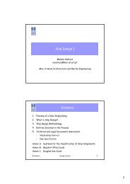
<strong>Hull</strong> <strong>Form</strong>Manuel VenturaShip <strong>Design</strong> IMSc in Marine Engineering and Naval Architecture<strong>Summary</strong>1. Introduction2. Types of hulls3. Development of the form• Systematic series• Geometric modeling4. Alteration of the form• Alteration of the Prismatic Coefficient• Alteration of the LCBM.Ventura <strong>Hull</strong> <strong>Form</strong> 21
IntroductionThe hull form is a compromise resulting from the need tosatisfy a set of different types of requirements:• Capacity– Volume– Spatial distribution of the volume– Displacement• Stability– Intact• Hydrodynamics– Service speed (loaded / ballast)– Seakeeping– Maneuverability• Functionality• Aesthetical– Pleasant formM.Ventura <strong>Hull</strong> <strong>Form</strong> 3Classification of <strong>Hull</strong>sType of Lift:• Displacement• Planning hulls• Semi-Planning• Hydrofoil<strong>Hull</strong> <strong>Form</strong>:• Monohull• Multi-hull– Catamaran– Trimaran– SWATHM.Ventura <strong>Hull</strong> <strong>Form</strong> 42
Types of LiftM.Ventura <strong>Hull</strong> <strong>Form</strong> 5Displacement <strong>Hull</strong>s (1)• Generally with round bottom and with a maximum displacementspeed that is determined by the length of the waterline• The displacement speed increases with the increase of the lengthof the waterline.• At its displacement speed, the hull is kept totally immersed.Type of ShipLength[ft]√LengthMax. Speed[knots]Container carrier95030.831Tanker55023.524America Cup758.79M.Ventura <strong>Hull</strong> <strong>Form</strong> 63
Displacement <strong>Hull</strong>s (2)Typical <strong>Form</strong> of Low Speed Displacement <strong>Hull</strong>Typical <strong>Form</strong> of High Speed Displacement <strong>Hull</strong> (Series 64)M.Ventura <strong>Hull</strong> <strong>Form</strong> 7Planning <strong>Hull</strong>s• <strong>Hull</strong> whose shape is characterized by a strong discontinuityalong the bottom, that may be planar or V-shaped.• The discontinuity has the shape of a hard chine• The objective is that the vessel plane in two small areas andso the wetted surface can be reduced in 60% or more.Typical form of a Planning hull (Series 62)M.Ventura <strong>Hull</strong> <strong>Form</strong> 84
Planning <strong>Hull</strong>s with Double ChineThere are also planning hulls with two chines.M.Ventura <strong>Hull</strong> <strong>Form</strong> 9Semi-Planning <strong>Hull</strong>s• Some displacement hulls when submitted to higher power canattain speeds higher than their displacement speeds.• In these conditions, the bow is raised above the waterline asthe speed increases and the hull is designated by semiplanning.• There are two main types:– With a narrow breadth and circular bilge (Nelson-style)– With hard-chinesM.Ventura <strong>Hull</strong> <strong>Form</strong> 105
Hydrofoil• The application of foils under the hull in order to obtain alift that, at higher speeds, allows the hull to raise above thewater reducing the resistance.• The first hydrofoil was designed by the Italian Forlanini in1906.M.Ventura <strong>Hull</strong> <strong>Form</strong> 11Multi-<strong>Hull</strong>s• Catamaran• Trimaran• SWATHM.Ventura <strong>Hull</strong> <strong>Form</strong> 126
CatamaranTypes of <strong>Hull</strong>:• Tunnel• Displacement• PlanningM.Ventura <strong>Hull</strong> <strong>Form</strong> 13Types of Catamaran <strong>Hull</strong>s• Tunnel– Lift– High speed– High power– Bad sea keeping in waves due to the planar bottom• Displacement– Impulsion– Wetted surface, friction resistance– Maximum speed limited– Subject to slammingM.Ventura <strong>Hull</strong> <strong>Form</strong> 147
EarthRace<strong>Hull</strong>: Wavepiercing TrimaranLength: 24m (78ft)Beam: 8m (24ft)Draft: 1.3m (4ft)Range: 3000nm (6000km)Maximum speed: 45 knots (90km/h)*Fuel: B100 Biodiesel (100%)Fuel Capacity: 10,000 liters (2500 gallons)Displacement: 10 tonConstruction: Carbon , Kevlar compositesCrew: 4Beds: 8Engines: 2 x 350kW (540 hp) CumminsMercruiserGearboxes: ZF 305A (single speed)Air intakes: top of wings to remain abovewaves while piercingWindscreen: 17mm laminated toughened glassM.Ventura <strong>Hull</strong> <strong>Form</strong> 17PentamaranM.Ventura <strong>Hull</strong> <strong>Form</strong> 189
Evolution of the Pentamaran• Patented on September 1996 - Patent expires on September 2016• Development and tank tests ADX 1996-1998• 11 technical papers published (1997 - 2003)• MARAD (USA) Sealift Development and tank tests 1998• Fast sealift ship DER on 1998• Project “ADX Express” 1999-2000 Fast Transatlantic containerservice• IZAR signs license on September 2001 – license exclusive for Ro-Ro and Ro-Pax in Europe• 2003 first contract for ship in IZAR with Buquebus – buildingstarted on 2004• July 2003 concept of frigate F5• September 2003 IZAR renews licenseM.Ventura <strong>Hull</strong> <strong>Form</strong> 19SWATH• Small Waterplane Area Twin <strong>Hull</strong>M.Ventura <strong>Hull</strong> <strong>Form</strong> 2010
Skjold SES• Fast patrol vessel built in 1997,at Umoe Mandal shipyard, forthe Norwegian Navy• Propulsion by two gas turbines, 2x 8160 Hp driving two waterjets• The air cushion is pressurized byventilators driven by two Dieselengines 2 x 735 KW• Speed of 47´in Beaufort 3 seastate and 55’ in still waterswww.knmskjold.orgM.Ventura <strong>Hull</strong> <strong>Form</strong> 23Air-Lubricated Ship (ALS)Concept patented by Donald E. Burg (2005)Air Lubricated Lifting Body Ship• A lifting body ship that has a blower pressurized air layerdisposed in the underside of its lifting body such that theair layer reduces wetted area friction and hence thepropulsive power required is greatly reduced.• Further, a water propulsor is supplied that takes in waterthrough transversely oriented water inlets in the top of thelifting body to thereby reduce turbulence and its associateddrag that would normally occur over the top of the liftingbody.M.Ventura US Patent No. <strong>Hull</strong> 6899045 <strong>Form</strong> - 2005-05-312412
SWEEP <strong>Hull</strong> (1)• Don Burg invented a new conceptof hull form designated SWEEP(Ship with Wave Energy EngulfingPropulsors)• Combines the advantages of thebulbous bow with those of a ALS(Air-Lubricated Ship)• Reduces the wave resistance ofdisplacement hullsM.Ventura The<strong>Hull</strong> Naval <strong>Form</strong> Architect, February 2006 25SWEEP <strong>Hull</strong> (2)M.Ventura <strong>Hull</strong> <strong>Form</strong> 2613
Development of the <strong>Hull</strong> <strong>Form</strong>Development of the <strong>Hull</strong> <strong>Form</strong>Methods of hull form development:• Systematic Series• Direct development from main lines• Alteration of parent hull formM.Ventura <strong>Hull</strong> <strong>Form</strong> 2814
Systematic Series (1)• Taylor Series, 1933– <strong>Hull</strong> based on the British cruiser “LEVIATHAN”, 1900– Original shape with a ram (esporão), cruiser stern and 2propellers• SSPA (Swedish State Shipbuilding Experimental Tank)– High speed ships, 2 propellers (1951)– Fast cargo ships, 1 propeller (1948/1950)– Tankers• Cb = 0.725 ~ 0.80• B/T= 2.30 ~ 2.50• L/B= 7.20 ~ 8.10– Cargo ships, 1 propeller• Cb = 0.525 ~ 0.750M.Ventura <strong>Hull</strong> <strong>Form</strong> 29Systematic Series (2)• Series 60, DTMB, 1953– Tested 62 models– Circular bilge, without deadrise– <strong>Hull</strong>s without bulb, U shaped sections– Cb = 0.60-0.65-0.70-0.75-0.80– B/T = 2.50 ~ 3.50– L/B = 5.50 ~ 8.50– 8 L.A. (0, 0.075, 0.25, 0.50, 0.75, 1.00, 1.25 e 1.50 T)– 25 Sections (numbered from bow to stern):• AR: 20, 19.5, 19, 18.5, 17, 16, 15, 14, 13, 12, 11• AV: 10,9,8,7,6,5,4,3,2,1,0.5,0– Contours AFT and FWD (7 L.A- at the center plane)– Fillet radius of the WLs, FWDM.Ventura <strong>Hull</strong> <strong>Form</strong> 3015
Systematic Series (3)• BSRA (British Ship Research Association)– <strong>Hull</strong>s with/without bulbous bow and deadrise– Original 1961:• Cb = 0.65 ~ 0.80• B/T= 2.10 ~ 3.45• L/B= 7.27– Extended in 1965:• Cb = 0.65 ~ 0.85• B/T= 2.10 ~ 3.20• L/B= 5.80 ~ 8.40M.Ventura <strong>Hull</strong> <strong>Form</strong> 31Systematic Series (4)• Series 62 (Series de Clemens), DTMB, 1963– Planning hulls– Constant deadrise (12.5°)• Series 64, DTMB, 1965– L/B = 8.45• Ship Research Institute of Japan, 1966– Cb = 0.80 ~ 0.82– B/T = 2.60 ~ 3.06– L/B = 5.50 ~ 6.70M.Ventura <strong>Hull</strong> <strong>Form</strong> 3216
Systematic Series (5)• FDS (Forschungszentrum des Deutschen Schiffbau), 1968– Cb = 0.85– B/T = 2.70– L/B = 6.60• NSMB (<strong>Net</strong>herlands Ship Model Basin), 1970– Cb = 0.80 ~ 0.85– B/T = 2.65– L/B = 6.50• HSDHF (High-Speed Displacement <strong>Hull</strong> <strong>Form</strong>s), 1984– Project sponsored by the Royal <strong>Net</strong>herlands Navy, UnitedStates Navy, Royal Australian Navy e MARIN– 40 models tested– Results never publishedM.Ventura <strong>Hull</strong> <strong>Form</strong> 33Systematic Series (6)• NPL Series, 1976 (National Physical Laboratory)– Displacement hulls, with circular bilge– L/B = 3.33 ~ 7.50– Stern panel– Forward sections with flare near the design waterline– High speed ships• NPL Extended– 10 hulls with Cb = 0.397– Application to catamarans• USCG Systematic Series of High Speed Planing <strong>Hull</strong>s– Dina H. Kowalyshyn and Bryson Metcalf (2006), SNAMETransactions, pp.268-309.M.Ventura <strong>Hull</strong> <strong>Form</strong> 3417
Systematic Series (7)• MARAD Systematic Series of Full-<strong>Form</strong> Ship Models, 1987– Low value of L/B– High value of B/T– Cb = 0.80 ~ 0.875– B/T = 3.00 ~ 4.75– L/B = 4.50 ~ 6.50• AMECRC (Australian Maritime Engineering CooperativeResearch Centre), 1998– Based on the HSDHF– Cb = 0.395 ~ 0.5– L/B = 6.0 ~ 8.0– B/T = 2.5 ~ 4.0– Used in multi-hullsM.Ventura <strong>Hull</strong> <strong>Form</strong> 35Systematic Series – Sailing Vessels• Delft Systematic Series, Modern Yacht Conference (1998) orChesapeake Symposium (1999) ????M.Ventura <strong>Hull</strong> <strong>Form</strong> 3618
Example: Taylor SeriesidetayloDimensions in M ?LPP B T DISV ?90, 18.5, 6.5, 6500AreaF, M2 LCB, M4.8, 0.1M.Ventura <strong>Hull</strong> <strong>Form</strong> 37Example: Series 60ideser60Dimensions in M ?LPP B T DISV ?90, 20, 6.5, 6800Area, M2 LCB, M1.5, -0.5M.Ventura <strong>Hull</strong> <strong>Form</strong> 3819
Example: BSRA Series (1)idebsrachose without bulb, 0 or with bulb, 1Dimensions in M ?LPP B T DISV ?120, 22.0, 7.0, 12500Standard areas of sections at FWD and AFT and LCBWith bulb: AreaF= 9.90 M2 AreaR=1.70 M2 LCB, M=0.034AF, M2 AA, M2 LCB, M ?10.0, 1.80, .05M.Ventura <strong>Hull</strong> <strong>Form</strong> 39Example: BSRA Series (2)M.Ventura <strong>Hull</strong> <strong>Form</strong> 4020
Example: Taylor Series (1)idetayloDimensions in M ?LPP B T DISV160, 24, 7.5, 22500Standard areas of sections FWD and AFT PP and LCB(M)AreaF, M2 LCB, M7.164 0.0227.2, 0.05M.Ventura <strong>Hull</strong> <strong>Form</strong> 41Example: Taylor Series (2)M.Ventura <strong>Hull</strong> <strong>Form</strong> 4221
Direct Development of the <strong>Hull</strong> <strong>Form</strong>Manuel VenturaShip <strong>Design</strong> IMSC in Marine Engineering and Naval ArchitectureData for <strong>Hull</strong> <strong>Form</strong> Development• The hull form can be defined from a set of parameters and a setof main curves• The parameters are the main dimensions and some hydrostaticcharacteristics (Ex.: ∆, Lcb, form coefficients, etc.)• The main dimensions are:– Length between perpendiculars (Lpp)– Breadth, molded (B)– Depth (D)– <strong>Design</strong> draught (T)• The form coefficients are:– Block Coefficient (C B)– Prismatic Coefficient (C P)– Midship Section Coefficient (C M)– Waterplane Area Coefficient (C WP)M.Ventura <strong>Hull</strong> <strong>Form</strong> 4422
Midship Section Coefficient (C M )Typical midship sections and corresponding C M valuesM.Ventura <strong>Hull</strong> <strong>Form</strong> 45Main Curves• Midship Section• Sectional Area Curve (SAC)• Load Waterline (LWL)• Deck at Side Line (DKL)• Flat of Bottom (FOB)• Flat of Side (FOS)• Profile (Centerline plane contour)M.Ventura <strong>Hull</strong> <strong>Form</strong> 4623
Midship Section( − C ) ⋅ B TR = 2 .33 ⋅ 1 ⋅BT ⋅ ⋅( 1−CM) −0.5h⋅( B−2b)MR =( B−b) 24⋅2K = −1.57112hM.Ventura <strong>Hull</strong> <strong>Form</strong> 47KSectional Area Curve• L1 – entry body• Lx – parallel body• L2 – run body• Am – area of midship sectionM.Ventura <strong>Hull</strong> <strong>Form</strong> 4824
Cb ≥ 0.80Length and Extent of Parallel MiddleBody (1)Length of the Parallel Body (Lx)0.30 Lpp ≤ Lx ≤ 0.35 Lpp0.70 ≤ Cb < 0.80 0.15 Lpp ≤ Lx ≤ 0.20 LppCb < 0.70 0L = L 1+ L X+ L 2L.C P= L.Cp 1+ L X+ L 2.Cp 2Baker Criterium (Hydrodinamics)L2= 4. 08B ⋅T⋅C MM.Ventura <strong>Hull</strong> <strong>Form</strong> 49Length and Extent of Parallel MiddleBody (2)Full Shaped <strong>Hull</strong>s0.75 L ≤ L ≤0.95L2 1 2( L ) = 0.1⇒ 1 δ LXδ %Bp/ (L/B) = 7p/ (L/B) < 7M.Ventura <strong>Hull</strong> <strong>Form</strong> 5025
Load Waterline (1)• 2D Line (planar curve)• Influences– Hydrostatic equilibrium (LCF)– Intact stability (transverse and longitudinal metacentric radius)– Propulsive resistanceM.Ventura <strong>Hull</strong> <strong>Form</strong> 51Load Waterline (2)• Values of the semi-angle of entrance (P 2) recommended (Pophanken,1939) as a function of the Prismatic Coefficient (C P):Cp0.550.600.650.700.750.800.85P28°9°9-10°10-14°21-33°33°37°The values shown must be multiplied by the factor ( L B)M.Ventura <strong>Hull</strong> <strong>Form</strong> 52726
Deck Line at Side• The actual line is 3D and results from the intersection ofthe deck with the side shell• Influenced by the requirements of work area on deck• It is easier to start with a sketch of a planar deck line atdepth level, based on the cargo area requirementsM.Ventura <strong>Hull</strong> <strong>Form</strong> 53Profile• Planar line, resulting from the intersection of the hull with thecenterline plane• Composed by 4 segments– Keel line– Stem contour– Stern contour– Sheer lineM.Ventura <strong>Hull</strong> <strong>Form</strong> 5427
Body Plan and Stem/Stern ContoursThe shape of the stem and stern contours is mostly relatedwith the propulsion performance and with the configuration ofthe propulsion and maneuvering systems.M.Ventura <strong>Hull</strong> <strong>Form</strong> 55Stern Contour• The figure represents some of the evolutions of the sternlines, from the spoon type (1) to the stern panel (2).• The shape of thecontour has changedfrom the solutions withstern post (cadaste)until the bulbous bowwhich is now standardin most ships.• In ships with PODpropulsion the sternshape becomes muchmore simplifiedM.Ventura <strong>Hull</strong> <strong>Form</strong> 5628
Influence of the Propulsion andManeuvering Systems in the <strong>Hull</strong> <strong>Form</strong>• Some parameters related with the Propulsion System:– Type of propulsor (Propeller, POD)– Number of propulsors– Existence of nozzle (tubeira)– Vertical position of the propeller shaft– Propeller diameter– Propeller clearances– Diameter of the propeller shaft– Diameter of the propeller boss• Some parameters related with the Maneuvering System:– Type of rudder– Dimensions of the rudder– Longitudinal position of the rudder (distance to the propeller)M.Ventura <strong>Hull</strong> <strong>Form</strong> 57Propeller Clearances (1)Det Norske Veritasa ≥ 0.2⋅Rb ≥c ≥[ m]( 0.7 − 0.04⋅Zp) ⋅ R [ m]( 0.48 − 0.02⋅Z ) ⋅ R [ m]e ≥ 0.07⋅R[ m]with:R : radius of propeller [m]Zp: number of bladespM.Ventura <strong>Hull</strong> <strong>Form</strong> 5829
Propeller Clearances (2)Lloyds Register of ShippingNo. of Blades3456a0.12 D0.12 D0.12 D0.12 Db1.800 KD1.500 KD1.275 KD1.125 KDc1.20 KD1.00 KD0.85 KD0.75 KDMin. valuet R0.15 D0.10 Dwith: t R= rudder thickness, measured at 0.7Rabove the axis of the shaft line [m]P = SHP [kW]R = propeller radius [m]⎛ L ⎞⎛3.48⋅Cb⋅P⎞D = propeller diameter [m]K = ⎜0.1+ + 0.333050⎟⎜L⎟⎝ ⎠⎝ ⎠Cb = block coefficient [-]L = rule length of the ship [m]M.Ventura <strong>Hull</strong> <strong>Form</strong> 59Propeller Clearances (3)Germanischer LloydM.Ventura <strong>Hull</strong> <strong>Form</strong> 6030
Stern ShapePropeller ClearanceRound poopM.Ventura <strong>Hull</strong> <strong>Form</strong> 61Stern PanelsM.Ventura <strong>Hull</strong> <strong>Form</strong> 6231
Stern PanelM.Ventura <strong>Hull</strong> <strong>Form</strong> 63Bow Contour (Stem)M.Ventura <strong>Hull</strong> <strong>Form</strong> 6432
BowM.Ventura <strong>Hull</strong> <strong>Form</strong> 65Knuckles (1)Knuckles are used to obtain some requiredcharacteristics, such as the increase ofthe local deck width, without the creationof mores areas of double curvature or ofvery high curvature.M.Ventura <strong>Hull</strong> <strong>Form</strong> 6633
Knuckles (2)• In general, knucklesare used above theload waterline, andtherefore without anegative impact in thehydrodynamicperformance• However, sometimesthey are used underthe design waterline,for instance in thetransition between thebulb and the hull, whenaddition bulbs are usedM.Ventura <strong>Hull</strong> <strong>Form</strong> 67Knuckles• Knuckles can be created to:– Enable a high angle of flare to be used in the lower part of thesections, without this carrying on become too extreme in theupper part– Avoid the end of forecastle deck projecting in a way that mightcause contact with dockside cranes or similar– Improve sea keeping (although there is disagreement over this)by the detachment of waves from the shell– Reduce shipbuilding cost by increasing the number of platesthat do not need to be rolled in two directions.• For economical reasons in manufacture, knuckles aregenerally best positioned at a short distance above a deck(due to block assembly reasons).M.Ventura <strong>Hull</strong> <strong>Form</strong> 6834
Elliptical Bow (1)Characteristics:• No bulb• Maximum produceability• Sections with vertical sides• Small bilge radius• Waterlines between the bilge and the knuckle with ellipticalextremities at the bow contour• Transition bottom/bow shaped as a quarter circleM.Ventura <strong>Hull</strong> <strong>Form</strong> 69Elliptical Bow (2)Production:• Area with a double curvature quite reduced• Web frame structure very simplifiedM.Ventura <strong>Hull</strong> <strong>Form</strong> 7035
Conical Bow (1)Characteristics:• Bulb shaped a conical section of large size covered by asemi-spherical area, extending forward of the bow contour• Bulb with good hydrodynamic characteristics with asignificant reduction of the profile of the wave generatedby the shipM.Ventura <strong>Hull</strong> <strong>Form</strong> 71Conical Bow (2)Production:• Increase of abt. 175% of plates with a double curvature in theforebody by comparison with the elliptical bow• Complex shaped transverse structure• Increase of costo of abt. 21% in relation to the elliptical bowM.Ventura <strong>Hull</strong> <strong>Form</strong> 7236
Spoon Type Bow (1)Characteristics:• Bow without bulb• Similar to the elliptical bow bit modified to improve the flow• Bilge radius increasing forward• Softer profile• Transition bottom/bow with elliptical shape of large sizeM.Ventura <strong>Hull</strong> <strong>Form</strong> 73Spoon Type Bow (2)Production:• Increase of abt. 142% of plates with double curvature in theforebody by comparison with the elliptical bow• Transverse structure with more complex shape• Increase of the cost of abt. 12.5% in relation to theelliptical bowM.Ventura <strong>Hull</strong> <strong>Form</strong> 7437
Bow with Bulb Simplified for Production (1)Characteristics:• Bulb simplified for production, built from conical shapedcomponentsM.Ventura <strong>Hull</strong> <strong>Form</strong> 75Bow with Bulb Simplified for Production (2)Production:• Increase of abt. 112% of number of plates with double curvaturein the forebody by comparison with an elliptical bow• Reduction of abt. 30% by comparison with a spoon bow• Reduction of abt. 63% by comparison with a conical bow• Transverse structure relatively simple• Increase the cost of abt. 14.1% in relation to the elliptical bow• Increase the cost of abt. 7.1% in relation to the conical bowM.Ventura <strong>Hull</strong> <strong>Form</strong> 7638
Direct Development of the <strong>Hull</strong> <strong>Form</strong>Main steps:• Sketch a load waterline• Draw a midship section and locate one copy in each end ofthe parallel middle body• Draw three sections in the forebody and three sections inthe aftbody in such a way to obtain for each one the areadefined in the Sectional Area Curve• Create 2 waterlines from the intersections with the existingsections and fair the lines obtained• Proceed with modifications of the initial sections untilsatisfactory faired lines are obtained• Draw a longitudinal section and fair the line• Continue to create sections and waterlines by the sameprocess described above…M.Ventura <strong>Hull</strong> <strong>Form</strong> 77Creation of the Main Deck• To generate the deck its is needed to to define first twotypes of lines:– Sheer line– Camber line(s)• Decks other than the main one (exposed) have a simplerplanar form, resulting from the intersection of an horizontalplane with the shellM.Ventura <strong>Hull</strong> <strong>Form</strong> 7839
Sheer LineStandard sheer line,in accordance withthe definition fromthe InternationalLoad Lines ConventionPolygonal sheer line,used in most currentmerchant shipsM.Ventura <strong>Hull</strong> <strong>Form</strong> 79Camber LineParabolic camber linePolygonal camber lineThe purpose of the camber is to facilitate the dischargeoverboard of water eventually on deck.The value of the maximum camber on the centerline plane isgenerally defined as a function of the ship’s breadth. Example:f = B/50M.Ventura <strong>Hull</strong> <strong>Form</strong> 8040
Generation of the Deck SurfaceSweep 1 Rail (1 section)TrimM.Ventura <strong>Hull</strong> <strong>Form</strong> 81Deck Line at SideCurve From Objects/ IntersectionM.Ventura <strong>Hull</strong> <strong>Form</strong> 8241
Openings on the Shell• The small openings, such as those from sea chests (caixasde mar), are not relevant for the Lines Plan• The openings of larger sizes shell be located in the LinesPlan– Thrusters tunnels– Intersection of the hawse pipes (escovéns) with the shellM.Ventura <strong>Hull</strong> <strong>Form</strong> 83Thruster Tunnel (1)• O túnel do impulsor deve estarlocalizado o mais a vante possívelpara maximizar o momento, e omais abaixo possível• O topo do túnel deve estar pelomenos um diametro abaixo dalinha de água• A linha de eixo do cilindrodeve ser normal ao plano demedianiaM.Ventura <strong>Hull</strong> <strong>Form</strong> 8442
Thruster Tunnel (2)The intersection of the tunnel with theshell can be chamfered (chanfrada) orto have a circular fillet (concordânciacircular)Near the intersection with theshell the tunnel changes fromcylindrical to conical shape toimprove the characteristics ofthe flow (reducing theturbulence) and decreasing thenegative influence in thepropulsive resistance.M.Ventura <strong>Hull</strong> <strong>Form</strong> 85Thruster Tunnel (3)• Generally the openings areprotected by grids• The grids shall be manufacturedwith bars with rounded edges,equally spaced• The bars shall be oriented indirection parallel to the maindirection of the water flow.M.Ventura <strong>Hull</strong> <strong>Form</strong> 8643
Hawse Pipes (Escovéns)The orientation of thehawse pipe and the shapeof the shell opening areconditioned mainly by theneed to facilitate thein/out movements of theanchor.M.Ventura <strong>Hull</strong> <strong>Form</strong> 87Bibliography (1)• Abt, C., Bade, S., Birk, L. E Harries, S. (2001), “Parametric <strong>Hull</strong><strong>Form</strong> <strong>Design</strong> – A Step Towards one Week Ship <strong>Design</strong>”, Proceedingsof PRADS’2001.• Abt, C., Harries, S., Heiman, J. e Winter, H. (2003), “FromRedesign to Optimal Ship Lines by Means of Parametric Modeling”,COMPIT’2003.• Bailey, D. (1976), "The NPL High Speed Round Bilge Displacement<strong>Hull</strong> Series", Maritime Technology Monograph, No. 4, RINAPublications. (** PROCURAR **)• Bedi, S. and Vickers, G.W. (1989), “Surface Lofting and Smoothingwith Skeletal-Lines”, Computer Aided Geometric <strong>Design</strong>, Vol.6,pp.87-96. (CD-ROM#34)• Calkins, Dale E.; Theodoracatos, Vassilios E. ; Aguilar, Glenn D. andBryant, Dennis M. (2009), "Small Craft <strong>Hull</strong> <strong>Form</strong> SurfaceDefinition in a High-Level Computer Graphics <strong>Design</strong> Environment",SNAMEM.Ventura <strong>Hull</strong> <strong>Form</strong> 8844
Bibliography (2)• Celniker, George and Welch, Will (1992), “Linear Constraints forDeformable B_Spline Surfaces”, ACM Symposium on Interactive3D Graphics, pp.165-170, Cambridge. (CD-ROM#34)• Gerritsma, J. ; Kerwin, J. E. and Newman, J. N. (1962), "Polynomialrepresentation and damping of Series 60 hull forms“, InternationalShipbuilding Progress, Vol.9.• Gertler, M. (1954), "A Reanalysis of the Original Test Data for theTaylor Standard Series", DTMB Report 806.• Koelman, H.J. (1997), “<strong>Hull</strong> <strong>Form</strong> <strong>Design</strong> and Fairing: TraditionRestored”, Proceedings of 6 th International Marine <strong>Design</strong>Conference, Vol.1, University of Newcastle, U.K.• Kuiper, G. (1970), "Preliminary <strong>Design</strong> of Ship Lines byMathematical Methods", Journal of Ship Research, Vol 14, pp. 52-66.M.Ventura <strong>Hull</strong> <strong>Form</strong> 89Bibliography (3)• Lap, A. (1954), "Diagrams for Determining the Resistance of SingleScrew Ships", International Shipbuilding Progress, Vol 1, No. 4.• Letcher, John (2009), "Principles of Naval ArchitectureSeries: The Geometry of Ships", SNAME.• Kawashima, H. E Hino, T. (2004), “A <strong>Hull</strong> <strong>Form</strong> Generation Methodon Initial <strong>Design</strong> Stage”, Proceedings of PRADS’2004.• Markov, N. e Suzuki, K. (2001), “<strong>Hull</strong> <strong>Form</strong> Optimisation by Shiftand Deformation of Ship Sections”, Journal of Ship Research,Vol.45, No.3, pp.197-204.• Moor, D., Parker, M. e Patullo, R. (1961), "The BSRA MethodicalSeries: An Overall Presentation", Transactions of RINA, Vol.103,pp.329-419.M.Ventura <strong>Hull</strong> <strong>Form</strong> 9045
Bibliography (4)• Nowacki, H., Creutz, G., and Munchmeyer, F. (1977), "Ship LinesCreation by Computer - Objectives, Methods and Results", FirstInternational Symposium on Computer-Aided <strong>Hull</strong> SurfaceDefinition (SCAHD77), pp 1-18, SNAME, Anapolis, MD.• Nowacki, H. and Reese, D. (1983), "<strong>Design</strong> and Fairing of ShipSurfaces", Surfaces in Computer Aided Geometric <strong>Design</strong>, NorthHolland, Eds. Barnhill, R. and Boehm, W., pp. 121-134. O’Neill, Wiliam C. (????), “Hydrofoil Ship <strong>Design</strong>”. (CD-ROM#34)• Pophanken, E. (1939), “Schiffbaukalender – Hilfsbuch derSchiffbauindustrie“, Deutch Verlagswerke, Berlin.• Reed, A. and Nowacki, H. (1974), "Interactive Creation of Fair ShipLines", Journal of Ship Research, Vol.18, pp.96-112.M.Ventura <strong>Hull</strong> <strong>Form</strong> 91Bibliography (5)• Sabit, A. S. (1972), “An Analysis of the Series 60 Results Part I –Analysis of <strong>Form</strong>s and Resistance Results”, InternationalShipbuilding Progress, Vol..19, pp.81-97. Savitsky, Daniel (2003), “On the Subject of High-SpeedMonohulls”, SNAME. (CD-ROM#34)• Sha, O. Misra, S. E Gokarn, R. (2004), “Ship <strong>Hull</strong> <strong>Form</strong> <strong>Design</strong> – AModular Approach”, Proceedings of PRADS’2004.• Soding, H. and Rabien, U., "<strong>Hull</strong> Surface <strong>Design</strong> by Modifying anExisting <strong>Hull</strong>", First International Symposium on Computer-Aided<strong>Hull</strong> Surface Definition (SCAHD77), pp 19-29, SNAME, Anapolis,MD, 1977.• Standerski, N. (1989), "The Generation of Ship <strong>Hull</strong>s With Given<strong>Design</strong> Parameters Using Tensor Product Surfaces", Theory andPractice of Geometric Modeling, Eds. Strasser, W. and Seidel, H.,Springer Verlag, pp. 65-79.M.Ventura <strong>Hull</strong> <strong>Form</strong> 9246
Bibliography (6) Holtrop, J. and Mennen, G. (1982), "An Approximate PowerPrediction Method", International Shipbuilding Progress, Vol 29,July.• Holtrop, J. (1984), "A Statistical Re-Analysis of Resistance andPropulsion Data", International Shipbuilding Progress, Vol 31, Nov. Narli, E. e Sarioz, K. (2004), "The Automated Fairing of Ship <strong>Hull</strong>Lines Using <strong>Form</strong>al Optimisation Methods", Turkish Journal ofEngineering and Environmenta Science", No.28, pp.157-166. (CD-Archive#2) Todd, F.H. (1963), “Series 60 - Methodical Experiments withModels of Single-Screw Merchant Ships”, David Taylor Model BasinResearch and Development Report No.1712. (CD-ROM#44) Westgaard, G. and Nowacki, H. (2001), “Construction of FairSurfaces over Irregular Meshes”, Journal of Computing andInformation Science in Engineering, Vol.3, 2001. (CD-ROM#41)M.Ventura <strong>Hull</strong> <strong>Form</strong> 93Simplified <strong>Hull</strong> <strong>Form</strong>s DefinedMathematically47
Wigley <strong>Hull</strong> <strong>Form</strong>• Simplified hull form, defined mathematically (Wigley, 1934)• Used in hydrodynamic studies and in optimization processes2 2⎧ ⎫⎧ ⎫B ⎪ ⎛2x⎞ ⎪⎪ ⎛ z ⎞ ⎪y( x, z)= ⎨1−⎜ ⎟ ⎬⎨1−⎜ ⎟ ⎬2 ⎩⎪ ⎝ L ⎠ ⎭⎩ ⎪⎪ ⎝T⎠ ⎭⎪x – distance from mid-ship (positive FWD)y – half-breadth in point (x,z)z – distance measured from the base line (positive in thedirection of the keel)Wigley, W.C.S. (1934), "A Comparison of Experiment and Calculated WaveProfiles and Wave Resistance for a <strong>Form</strong> Having Parabolic Waterlines",Proceedings of Royal Society, Series A.M.Ventura <strong>Hull</strong> <strong>Form</strong> 95Wigley <strong>Hull</strong> <strong>Form</strong><strong>Hull</strong> Symmetric FWD/AFT and withParabolic WaterlinesM.Ventura <strong>Hull</strong> <strong>Form</strong> 9648