Charles Endirect Ltd
Download Selection Information - Charles Endirect Ltd
Download Selection Information - Charles Endirect Ltd

Create successful ePaper yourself
Turn your PDF publications into a flip-book with our unique Google optimized e-Paper software.
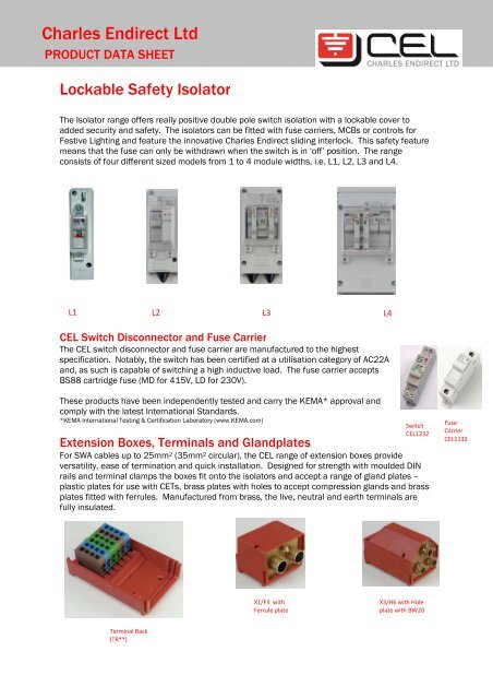
<strong>Charles</strong> <strong>Endirect</strong> <strong>Ltd</strong>PRODUCT DATA SHEETLockable Safety IsolatorThe Isolator range offers really positive double pole switch isolation with a lockable cover toadded security and safety. The isolators can be fitted with fuse carriers, MCBs or controls forFestive Lighting and feature the innovative <strong>Charles</strong> <strong>Endirect</strong> sliding interlock. This safety featuremeans that the fuse can only be withdrawn when the switch is in ‘off’ position. The rangeconsists of four different sized models from 1 to 4 module widths, i.e. L1, L2, L3 and L4.L1L2L3L4CEL Switch Disconnector and Fuse CarrierThe CEL switch disconnector and fuse carrier are manufactured to the highestspecification. Notably, the switch has been certified at a utilisation category of AC22Aand, as such is capable of switching a high inductive load. The fuse carrier acceptsBS88 cartridge fuse (MD for 415V, LD for 230V).These products have been independently tested and carry the KEMA* approval andcomply with the latest International Standards.*KEMA International Testing & Certification Laboratory (www.KEMA.com)Extension Boxes, Terminals and GlandplatesSwitchCEL1232For SWA cables up to 25mm 2 (35mm 2 circular), the CEL range of extension boxes provideversatility, ease of termination and quick installation. Designed for strength with moulded DINrails and terminal clamps the boxes fit onto the isolators and accept a range of gland plates –plastic plates for use with CETs, brass plates with holes to accept compression glands and brassplates fitted with ferrules. Manufactured from brass, the live, neutral and earth terminals arefully insulated.FuseCarrierCEL1132X1/F4 withFerrule plateX3/H6 with Holeplate with BW20Terminal Rack(TR**)
GLAND PLATES AND EXTENSION BOXESIsolatorEnclosureL1L2L3GlandPlatesPlasticGrommetA* = PlasticB* = BrassHolesC* = BrassFerrulesK* = PlasticM* = BrassHolesP* = BrassFerrulesX6X0X4Extension Boxes and Their Gland PlatesN/A- accepts A, B and C Gland Plates- accepts X1, X2, X3 and D, E and F Gland Plates- accepts K, M and P Gland PlatesD* = Plastic X1 - accept D, E and F Gland PlatesL4E* = BrassHolesX2 - accept D, E and F Gland PlatesX3 - accepts G, H and J Gland PlatesF* = Brass X5 - fits onto X3 for extra termination space and acceptsFerrulesG, H and J Plates* Digit to denote number and size of holes/ferrulesTermination RacksThere is a wide range of terminal block arrangements in the extension boxes to facilitatethe termination and looping of larger cables. These are Termination Racks (.../TR../...).Selection Chart for Standard Types of IsolatorsGuide to using the chart in following pages:To identify required product :1. Select incoming cable size in first column, e.g. 4mm, 3C2. Select incoming cable configuration in second column, e.g.single looped3. Select number of outgoing fused circuits, e.g. 1 upward circuit4. Select gland option, e.g. BW glandsIn the example above (4.0mm 3C incoming looped with 1 upward fused circuit withcompression glands), the required unit is L2/SFE/B1.(Note: the same unit with a 6 amp MCB would be L2/SM6E/B1.)Isolator with Pre-Wired Tails IsolatorOur standard double pole, single fuse isolator can be supplied fitted with an internalearth, plastic gland plate and incoming tails including two earth tails, one with 8mmcrimpOrder Reference: L2/SFE/A1/6.0/350+350E+510E/M8 Lug Tailswww.charlesendirect.comTel@ 01963 828400 October 2013
Isolator Selection Chart for Electricity Board SupplyIncomingCable SizeIncoming Cable 2 xDouble Insulated TailsOut GoingFused CircuitsGlandsLSIOrder ReferenceDimensions Hx W x D (mm)2.5mm - 6.0mm DI Tails x 21 x UpL2/SF/A1 142 x 57 x 82Pre-fitted incoming tails1 x Up L2/SFE/A1/6.0/350+350E+510E/M8 Lug142 x 57 x 82L3/S2F/K32.5mm - 6.0mm DI Tails x 22 x Up154 x 79 x 822.5mm - 6.0mm DI Tails x 23 x UpL4/S3FNE/D3 168 x 95 x 90DI Tails + 1 x 6mm FusedBW/CW20 L3/S2F/M3 (1D)1 x Up2.5mm - 6.0mm Downward Spur1 x DownFerrulesL3/S2F/P4 (1D)154 x 79 x 82DI Tail + 1 x 6mm Fused2 x UpBW20 CW20(CEL)L4/S3FNE/E3(1D)2.5mm - 6.0mm Downward Spur1 x DownFerrulesL4/S3FNE/F12(1D)168 x 95 x 90DI Tails + 2 x 6mm FusedBW/CW20 L4/S3F/TR12/H61 x Up2.5mm - 6.0mm Downward Spur2 x DownFerrulesL4/S3F/TR12/J7312 x 95 x 90When MCB is required substitute F for M plus MCB Current Rating, e.g. 6 Amp MCB = M6L2/SF/..L2/SF/A1Isolator Selection Chart for Private Supply NetworksIncomingCable SizeIncoming CableConfigurationOut GoingFused CircuitsGlandsLSIOrder ReferenceDimensions Hx W x D (mm)2.5mm. 4.0mm.3C.2.5mm. 4.0mm.3C.2.5mm. 4.0mm.3C.2.5mm. 4.0mm.3C.2.5mm. 4.0mm.3C.2.5mm. 4.0mm.3C.2.5mm. 4.0mm.3C.SingleSingle or Two LoopedThree Looped (TwoLooped + Unfused Spur)Single or Two LoopedThree Looped (TwoLooped + Unfused Spur)Single or Two LoopedThree Looped (TwoLooped + Unfused Spur)1 x Up1 x Up1 x Up2 x Up2 x Up3 x Up3 x UpWhen MCB is required substitute F for M plus MCB Current Rating, e.g. 6 Amp MCB = M6BW/CW20 L2/SFE/B1Ferrules L2/SFE/C2 142 x 57 x 82CETL2/SFE/A1BW/CW20 L3/SF/M3Ferrules L3/SF/P4 154 x 79 x 82CETL3/SF/K3BW/CW20 L3/SF/TR2/X0/E6Ferrules L3/SF/TR2/X0/F6 290 x 79 x 82CETL3/SF/TR2/X0/D6BW/CW20 L3/S2F/M3Ferrules L3/S2F/P4 154 x 79 x 82CETL3/S2F/K3BW/CW20 L3/S2F/TR2/X0/E6168 x 95 x 90Ferrules L3/S2F/TR2/X0/F6 290 x 79 x 82CETL3/S2F/TR2/X0/D6BW/CW20 L4/S3FNE/E3Ferrules L4/S3FNE/F4 168 x 95 x 90CETL4/S3FNE/D3BW/CW20 L4/S3FN/TR4/E6 312 x 96 x 90Ferrules L4/S3FN/TR4/F6 312 x 96 x 90CET L4/S3FNE/TR4/D3 312 x 96 x 90L3/S2F/TR2/...L3/S2F/TR2/P4
IncomingCable SizeIncoming Cable 2 xDouble Insulated TailsOut GoingFused CircuitsGlandsLSIOrder ReferenceDimensions Hx W x D (mm)6.00mm. 3C. Single 1 x Up6.00mm. 3C.6.00mm. 3C.6.00mm. 3C. Two Looped 1 X Up6.00mm. 3C.6.00mm. 3C.6.00mm. 3C.6.00mm. 3C.6.00mm. 3C.6.00mm. 3C.SingleSingleThree Looped (TwoLooped + Unfused Spur)Two LoopedThree Looped (TwoLooped + Unfused Spur)Three Looped (TwoLooped + Unfused Spur)Single + 1 x 6mm FusedDownward SpurSingle + 1 x 6mm FusedDownward Spur2 x Up3 x Up1 x Up2 x Up2 x Up6.00mm. 3C. Two Looped 3 x Up6.00mm. 3C.6.00mm. 3C.6.00mm. 3C.6.00mm. 3C.6.00mm. 3C.Looped + 1 x 6mm FusedDownward SpurSingle + 1 x 6mm FusedDownward SpurLooped + 1 x 6mm FusedDownward SpurSingle + 2 x 6mm FusedDownward SpurLooped + 2 x 6mm FusedDownward Spur3 x Up1 x Up1 x Down2 x Up1 x Down1 x Up1 x Down2 x Up1 x Down2 x Up1 x Down1 x Up2 x Down1 x Up2 x DownBW/CW20 L2/SFE/B1Ferrules L2/SFE/C2 142 x 57 x 82CETL2/SFE/A1BW/CW20 L3/S2F/M3Ferrules L3/S2F/P4 154 x 79 x 82CETL3/S2F/K3BW/CW20 L4/S3FNE/E3Ferrules L4/S3FNE/F4 168 x 95 x 90CETL4/S3FNE/D3BW/CW20 L3/SF/TR2/M3Ferrules L3/SF/TR2/P4 254 x 79 x 82CETL3/SF/TR2/K3BW/CW20 L3/SF/TR2/X0/E6Ferrules L3/SF/TR2/X0/F6 290 x 79 x 82CETL3/SF/TR2/X0/D6BW/CW20 L3/S2F/TR2/M3Ferrules L3/S2F/TR2/P4 168 x 95 x 90CETL3/S2F/TR2/K3BW/CW20 L3/S2F/TR2/X0/E6Ferrules L3/S2F/TR2/X0/F6 290 x 79 x 82CETL3/S2F/TR2/X0/D6BW/CW20 L4/S3FN/TR4/E3Ferrules L4/S3FN/TR4/F4 312 x 96 x 90CETL4/S3FN/TR4/D3BW/CW20 L4/S3FN/TR4/E6Ferrules L4/S3FN/TR4/F6 312 x 96 x 90CETL4/S3FN/TR4/D6BW/CW20 L3/S2F/M3(1D)Ferrules L3/S2F/P4(1D) 154 x 79 x 82CETL3/S2F/K3(1D)BW/CW20 L4/S3FNE/E3(1D)Ferrules L4/S3FNE/F4(1D) 168 x 95 x 90CETL4/S3FNE/D3(1D)BW/CW20 L3/S2F/TR9/X0/E6Ferrules L3/S2F/TR9/X0/F6 290 x 79 x 82CETL3/S2F/TR9/X0/D6BW/CW20 L4/S3FN/TR24/E3Ferrules L4/S3FN/TR24/F4 312 x 96 x 90CETL4/S3FN/TR24/D3BW/CW20 L4/S3FN/TR24/E6Ferrules L4/S3FN/TR24/F6 312 x 96 x 90CETL4/S3FN/TR24/D6BW/CW20 L4/S3F/TR12/H6Ferrules L4/S3F/TR12/J7 312 x 96 x 99CETL4/S3F/TR12/G6BW/CW20 L4/S3F/TR12/H10Ferrules L4/S3F/TR12/J20 312 x 96 x 99CETL4/S3F/TR12/G10BW/CW20 L4/SF/TR5/E36.00mm.Single or Two Looped 1 x Up (230V) Ferrules L4/SF/TR5/F4 377 x 96 x 904C.(TP&N)CETL4/SF/TR5/D3When MCB is required substitute F for M plus MCB Current Rating, e.g. 6 Amp MCB = M6L4/S3F/TR12/...L4/S3F/ ...
IncomingCable SizeIncoming Cable 2 xDouble Insulated TailsOut GoingFused CircuitsGlandsLSIOrder ReferenceDimensions Hx W x D (mm)10.00mm. 3C. Single 1 x Up10.00mm. 3C. Single 2 x Up10.00mm. 3C. Single 3 x Up10.00mm. 3C.10.00mm. 3C.10.00mm. 3C. Two Looped 2 x Up10.00mm. 3C.10.00mm. 3C. Two Looped 3 x Up10.00mm. 3C.10.00mm. 3C.10.00mm. 3C.10.00mm. 3C.10.00mm. 3C.10.00mm.4C.(TP&N)Two LoopedThree Looped (TwoLooped + Unfused Spur)Three Looped (TwoLooped + Unfused Spur)Three Looped (TwoLooped + Unfused Spur)Single or Looped + 1 x10mm Fused DownwardSpurSingle + 1 x 10mm FusedDownward SpurSingle or Looped + 1 x10mm Fused DownwardSpurSingle or Looped + 2 x6mm Fused DownwardSpurSingle or Two Looped1 x Up1 x Up2 x Up3 x Up1 x Up1 x Down2 x Up1 x Down2 x Up1 x Down1 x Up2 x DownBW/CW20 L3/SF/M3Ferrules L3/SF/P4 154 x 79 x 82CETL3/SF/K3BW/CW20 L3/S2F/M3Ferrules L3/S2F/P4 154 x 79 x 82CETL3/S2F/K3BW/CW20 L4/S3FNE/E3Ferrules L4/S3FNE/F4 168 x 95 x 90CETL4/S3FNE/D3BW/CW20 L3/SF/TR2/M3Ferrules L3/SF/TR2/P4 168 x 95 x 90CETL3/SF/TR2/K3BW/CW20 L3/SF/TR2/X0/E6Ferrules L3/SF/TR2/X0/F6 290 x 79 x 82CETL3/SF/TR2/X0/D6BW/CW20 L3/S2F/TR2/M3Ferrules L3/S2F/TR2/P4 168 x 95 x 90CETL3/S2F/TR2/K3BW/CW20 L3/S2F/TR2/X0/E6Ferrules L3/S2F/TR2/X0/F6 290 x 79 x 82CETL3/S2F/TR2/X0/D6BW/CW20 L4/S3FN/TR4/E3Ferrules L4/S3FN/TR4/F4 312 x 96 x 90CETL4/S3FN/TR4/D3BW/CW20 L4/S3FN/TR4/E6Ferrules L4/S3FN/TR4/F6 312 x 96 x 90CETL4/S3FN/TR4/D6BW/CW20 L3/S2F/TR9/X0/E6 290 x 79 x 82Ferrules L3/S2F/TR9/X0/F6 290 x 79 x 82CET (Single) L3/S2F/TR9/K3 168 x 95 x 90CET (Looped) L3/S2F/TR9/X0/D6 290 x 79 x 82BW/CW20L4/S3FN/TR24/E3Ferrules L4/S3FN/TR24/F4 312 x 96 x 90CETL4/S3FN/TR24/D3BW/CW20 L4/S3FN/TR24/E6Ferrules L4/S3FN/TR24/F6 312 x 96 x 90CETL4/S3FN/TR24/D6BW/CW20 L4/S3F/TR12/H10Ferrules L4/S3F/TR12/J20 312 x 96 x 99CET (Single) L4/S3F/TR12/G6CET (Looped) L4/S3F/TR12/G10BW/CW25 L4/SF/TR5/E41 x Up (230V) Ferrules L4/SF/TR5/F4 377 x 96 x 99CETL4/SF/TR5/D4When MCB is required substitute F for M plus MCB Current Rating, e.g. 6 Amp MCB = M6L3/S2F/K3L3/S2F/ ...
IncomingCable SizeIncoming Cable 2 xDouble Insulated TailsOut GoingFused CircuitsGlandsLSIOrder ReferenceDimensions Hx W x D (mm)16.00mm. 3C. Single or Two Looped 1 x Up16.00mm. 3C.16.00mm. 3C.16.00mm. 3C.16.00mm. 3C. Single or Two Looped 3 x Up16.00mm. 3C.16.00mm. 3C.16.00mm. 3C.16.00mm.4C.(TP&N)Three Looped (TwoLooped + Unfused Spur)Single or Two LoopedThree Looped (TwoLooped + Unfused Spur)Three Looped (TwoLooped + Unfused Spur)Single or Looped + 1 x10mm Fused DownwardSpurSingle or Looped + 1 x10mm Fused DownwardSpurSingle or Two Looped1 x Up2 x Up2 x Up3 x Up1 x Up1 x Down2 x Up1 x DownBW/CW25 L4/SF/TR4/E4Ferrules L4/SF/TR4/F4 312 x 96 x 90CETL4/SF/TR4/D3BW/CW25 L4/SF/TR8/H7Ferrules L4/SF/TR8/J7 377 x 96 x 99CETL4/SF/TR8/G6BW/CW25 L4/S2F/TR4/E4Ferrules L4/S2F/TR4/F4 312 x 96 x 90CETL4/S2F/TR4/D3BW/CW25 L4/S2F/TR8/H7Ferrules L4/S2F/TR8/J7 377 x 96 x 99CETL4/S2F/TR8/G6BW/CW25 L4/S3FN/TR4/E4Ferrules L4/S3FN/TR4/F4 312 x 96 x 90CETL4/S3FN/TR4/D3BW/CW25 L4/S3FN/TR8/H7Ferrules L4/S3FN/TR8/J7 377 x 96 x 99CETL4/S3FN/TR8/G6BW/CW25 L4/S2F/TR10/H8 312 x 96 x 99Ferrules L4/S2F/TR10/J7 312 x 96 x 99CET (Single) L4/S2F/TR24/D3 312 x 96 x 90CET (Looped) L4/S2F/TR10/G6 312 x 96 x 99BW/CW25 L4/S3FN/TR10/H8 312 x 96 x 99Ferrules L4/S3FN/TR10/J7 312 x 96 x 99CET (Single) L4/S3FN/TR24/D3 312 x 96 x 90CET (Looped) L4/S3FN/TR10/G6 312 x 96 x 99BW/CW25 L4/SF/TR5/E41 x Up (230V) Ferrules L4/SF/TR5/F4 312 x 96 x 90CETL4/SF/TR5/D4When MCB is required substitute F for M plus MCB Current Rating, e.g. 6 Amp MCB = M6IncomingCable SizeIncoming CableConfigurationOut GoingFused CircuitsGlandsLSIOrder ReferenceDimensions Hx W x D (mm)25.00mm. 3C. Single or Two Looped 1 x Up25.00mm. 3C.Three Looped (TwoLooped + Unfused Spur)1 x Up25.00mm. 3C. Single or Two Looped 2 x Up25.00mm. 3C.Three Looped (TwoLooped + Unfused Spur)2 x Up25.00mm. 3C. Single or Two Looped 3 x Up25.00mm. 3C.25.00mm. 3C.25.00mm. 3C.25.00mm.4C.(TP&N)Three Looped (TwoLooped + Unfused Spur)Single or Looped + 1 x10mm Fused DownwardSpurSingle or Looped + 1 x10mm Fused DownwardSpurSingle or Two Looped3 x Up1 x Up1 x Down2 x Up1 x Down1 x Up (230V)When MCB is required substitute F for M plus MCB Current Rating, e.g. 6 Amp MCB = M6BW/CW25 L4/SF/TR4/E4Ferrules L4/SF/TR4/F4 312 x 96 x 90CETL4/SF/TR4/D4BW/CW25 L4/SF/TR8/H7Ferrules L4/SF/TR8/J7 377 x 96 x 99CETL4/SF/TR8/G7BW/CW25 L4/S2F/TR4/E4Ferrules L4/S2F/TR4/F4 312 x 96 x 90CETL4/S2F/TR4/D4BW/CW25 L4/S2F/TR8/H7Ferrules L4/S2F/TR8/J7 377 x 96 x 99CETL4/S2F/TR8/G7BW/CW25 L4/S3FN/TR4/E4Ferrules L4/S3FN/TR4/F4 312 x 96 x 90CETL4/S3FN/TR4/D4BW/CW25 L4/S3FN/TR8/H7Ferrules L4/S3FN/TR8/J7 377 x 96 x 99CETL4/S3FN/TR8/G7BW/CW25 L4/S2F/TR10/H8 312 x 96 x 99Ferrules L4/S2F/TR10/J7 312 x 96 x 99CET (Single) L4/S2F/TR24/D4 312 x 96 x 90CET L4/S2F/TR10/G8 312 x 96 x 99BW/CW25 L4/S3FN/TR10/H8 312 x 96 x 99Ferrules L4/S3FN/TR10/J7 312 x 96 x 99CET (Single) L4/S3FN/TR24/D4 312 x 96 x 90CET (Looped) L4/S3FN/TR10/G8 312 x 96 x 99BW/CW32 L4/SF/TR6/H27 312 x 96 x 99Ferrules L4/SF/TR5/F23 312 x 96 x 90CET L4/SF/TR7/D4 273 x 96 x 90For applications to suit 35mm cables please contact CEL Customer Services Team for assistance:Tel: 01963 828400info@charlesendirect.com