MSC Vertriebs GmbH Design Center Neufahrn PISA-PIII-TwisterT
MSC Vertriebs GmbH Design Center Neufahrn PISA-PIII-TwisterT
MSC Vertriebs GmbH Design Center Neufahrn PISA-PIII-TwisterT

You also want an ePaper? Increase the reach of your titles
YUMPU automatically turns print PDFs into web optimized ePapers that Google loves.
10 / 06 / 2003<br />
<strong>MSC</strong> <strong>Vertriebs</strong> <strong>GmbH</strong><br />
<strong>Design</strong> <strong>Center</strong> <strong>Neufahrn</strong><br />
1<br />
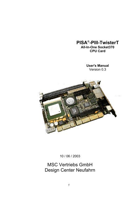
PISA ® -<strong>PIII</strong>-<strong>TwisterT</strong><br />
All-In-One Socket370<br />
CPU Card<br />
User's Manual<br />
Version 0.3
Copyright Notice<br />
This document is copyrighted, 2002, by <strong>MSC</strong> <strong>Vertriebs</strong> <strong>GmbH</strong>. All rights are reserved.<br />
<strong>MSC</strong> <strong>Vertriebs</strong> <strong>GmbH</strong> reserves the right to make improvements to the products described<br />
in this manual at any time without notice.<br />
No part of this manual may be reproduced, copied, translated or transmitted in any form<br />
or by any means without the prior written permission of <strong>MSC</strong> <strong>Vertriebs</strong> <strong>GmbH</strong>.<br />
Information provided in this manual is intended to be accurate and reliable. However,<br />
<strong>MSC</strong> <strong>Vertriebs</strong> <strong>GmbH</strong> assumes no responsibility for its use, nor<br />
for any infringements upon the rights of third parties which may result from its<br />
use.<br />
� Important Information<br />
This product is not an end user product. It was developed and manufactured for<br />
further processing by trained personnel.<br />
EMC Rules<br />
This unit has to be installed in a shielded housing. If not installed in a properly<br />
shielded enclosure, and used in accordance with the instruction manual, this<br />
product may cause radio interference in which case the user may be required to<br />
take adequate measures at his or her own expense.<br />
Care and handling precautions for Lithium batteries<br />
• Do not short circuit<br />
• Do not heat or incinerate<br />
• Do not charge<br />
• Do not deform or disassemble<br />
• Do not apply solder directly<br />
• Always observe proper polarities<br />
� Caution!<br />
Danger of explosion if the battery is incorrectly replaced. When<br />
battery replacement is necessary use only the exact same battery or a<br />
battery recommended by the manufacturer.<br />
Pay attention to the local area regulations regarding the proper disposal of used<br />
batteries.<br />
2
1 General Information .......................................................................5<br />
1.1 Introduction..................................................................................5<br />
1.2 Block Diagram .............................................................................6<br />
1.3 Specifications...............................................................................7<br />
1.4 Board Layout ...............................................................................12<br />
1.4.1 Top Side ..............................................................................12<br />
1.4.2 Bottom Side .........................................................................13<br />
2 Installation ......................................................................................14<br />
2.1 CPU .............................................................................................14<br />
2.2 SDRAM........................................................................................15<br />
2.3 PCI I/O Voltage............................................................................16<br />
2.4 Clear CMOS Data and BIOS Flash Recovery Jumper.................17<br />
2.5 COM1, COM3 and COM4 (RS232) .............................................17<br />
2.6 COM2 (RS232/422/485, IrDA).....................................................18<br />
2.7 LCD Interfaces.............................................................................19<br />
2.7.1 LCD Connectors ..................................................................20<br />
2.7.2 Digital Display Data Mapping...............................................21<br />
2.8 AUX Power Connector.................................................................22<br />
2.9 Fan Connectors ...........................................................................22<br />
2.10 Onboard Reset Switch.................................................................23<br />
2.11 System Header............................................................................23<br />
2.12 Onboard Buzzer...........................................................................24<br />
2.13 Onboard Sound ...........................................................................24<br />
2.14 EIDE ............................................................................................25<br />
2.14.1 Primary Channel ..................................................................25<br />
2.14.2 Secondary Channel (optionally), CompactFlash..................26<br />
2.15 Floppy Disk..................................................................................27<br />
2.16 Parallel Port .................................................................................27<br />
2.17 Internal USB ................................................................................27<br />
2.18 External USB ...............................................................................28<br />
2.19 RJ45 (Ethernet) ...........................................................................28<br />
2.20 CRT .............................................................................................29<br />
2.21 Keyboard / Mouse Mini-DIN Connector .......................................29<br />
2.22 PISA Edge-Connector .................................................................30<br />
2.23 PC/104 Conncetor .......................................................................31<br />
2.24 Watchdog ....................................................................................32<br />
2.25 PCI Interrupt Routing ...................................................................32<br />
2.26 Interrupts, DMA channels, Upper memory...................................33<br />
3
Trademarks :<br />
PISA is a registered trademark of JUMPtec Industrielle Computertechnik AG<br />
JUMPtec is the registered trademark of JUMPtec Industrielle Computertechnik AG<br />
4
PISA-<strong>PIII</strong>-<strong>TwisterT</strong> User's Manual Installation<br />
1 General Information<br />
1.1 Introduction<br />
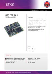
The PISA-<strong>PIII</strong>-<strong>TwisterT</strong> is an all-in-one single board computer card for the PISA bus (PISA = PCI +<br />
ISA), designed for Intel‘s new generation Pentium TM III and Celeron TM Tualatin CPUs, as well as<br />
VIA’s C3 CPUs in Socket370 package.<br />
The board uses the VIA ProSavage PN133T chipset (VT8696 <strong>TwisterT</strong> Northbridge and<br />
VT86286B Southbridge) runing at 100 MHz or 133 MHz front side bus.<br />
With an LCD/CRT SXVGA controller, up to two 100MBit Ethernet controllers, an EIDE controller, a<br />
floppy controller, as well as sound-, LPT-, keyboard and mouse interfaces, four serial<br />
communication ports and four USB ports, the PISA-<strong>PIII</strong>-<strong>TwisterT</strong> packs all the functions of an<br />
industrial computer onto a single card. This makes it an ideal solution for embedded applications.<br />
Two 168-pin standard DIMM socket are giving you the flexibility to configure your system up to<br />
1 GByte of 3.3V SDRAM (PC100 and PC133) .<br />
The integrated S3 ProSavage4 AGP 4x 2D/3D/Video accelerator with 128-bit graphic engine uses<br />
8, 16 or 32 MByte of system memory. The PISA-<strong>PIII</strong>-<strong>TwisterT</strong> board includes one 36-bit<br />
DSTN/TFT flat panel and one 2-channel 110 MHz LVDS interface by actually supporting display<br />
types with resolutions up to 1400 x 1050 pixels.<br />
Up to two Intel 82551ER PCI 10/100BaseTx Ethernet controllers can be equipped which give<br />
access to high speed networks through standard RJ45 connectors in the front panel of the board.<br />
The PISA-<strong>PIII</strong>-<strong>TwisterT</strong> includes a high speed, local bus EIDE controller. This controller supports<br />
(through ATA PIO) mode3, mode4 and Ultra DMA-33/66/100 hard disks, enabling data transfer<br />
rates up to 100 MByte/sec. Up to two devices, including large hard disks, CD-ROM drives, tape<br />
backup drives, or other IDE devices may be connected to the 40pin 2,54mm primary IDE header.<br />
Optionally the secondary EIDE port can be accessed by mounting a CompactFlash connector onto<br />
the solder side of the board.<br />
Onboard features also include four high-speed RS-232 serial ports (one configurable as<br />
RS422/485), one IrDA, one bi-directional SPP/EPP/ECP parallel port, one floppy drive controller<br />
and four USB 1.1 ports.<br />
128kbit/sec stereo applications are supported by a SoundBlasterPro/Direct Sound AC97 Digital<br />
Audio controller.<br />
An onboard 5.25” power connector give the possibility to use the PISA-<strong>PIII</strong>-<strong>TwisterT</strong> as a<br />
standalone system (without a backplane). The implemented PC/104 interface allows you to install<br />
additional functions using standard PC/104 modules.<br />
Please visit our web site http://www.msc.de (->products ->downloads ->PISA)<br />
where you can find drivers, firmware updates and documentation.<br />
5
PISA-<strong>PIII</strong>-<strong>TwisterT</strong> User's Manual Installation<br />
1.2 Block Diagram<br />
+3,3V<br />
Inverter Power<br />
Socket 370<br />
(FC-PGA)<br />
Core<br />
Voltage<br />
PISA Twister-T<br />
+ 5V<br />
I/O Voltage<br />
FAN Power FAN Power Power In<br />
GND + 5V + 12V<br />
FSB<br />
+5V<br />
GND<br />
+12V<br />
+12V<br />
Tacho<br />
GND<br />
+12V<br />
Tacho<br />
GND<br />
CRT<br />
CRT<br />
Display<br />
PN133T<br />
(VIA Twister-T)<br />
VT8606 Northbridge<br />
S3 Savage4 2D/3D<br />
Graphics Accelerator<br />
DRAM DIMM<br />
max. 512 MB<br />
+5V<br />
GND<br />
36Bit Digital<br />
LVDS Channel 1<br />
LVDS Channel 2<br />
+12V<br />
DRAM DIMM<br />
max. 512 MB<br />
Line-In, Line-Out;<br />
CD-In, MIC<br />
PCI<br />
ATX-<br />
Etension<br />
CompactFlash<br />
(optional)<br />
PISA<br />
Lithium<br />
Battery<br />
-12V<br />
Tacho<br />
VCC5<br />
VCC3<br />
VCCIO<br />
VCC12+<br />
Temp CPU<br />
Temp EXT<br />
Speaker<br />
CODEC<br />
VT1612A<br />
PC/104<br />
-5V<br />
6<br />
PS_ON<br />
PWR_BTN#<br />
3V3_SB<br />
EIDE2<br />
U Bat<br />
System Monitoring<br />
Intel<br />
82551ER<br />
LAN<br />
Controller<br />
Intel<br />
82551ER<br />
LAN<br />
Controller<br />
VIA<br />
Southbridge<br />
VT82C686B<br />
ISA<br />
SMB<br />
EIDE1<br />
USB[0:1]<br />
USB[0:2]<br />
LPT<br />
COM1<br />
COM2<br />
IrDA<br />
Keyboard<br />
Mouse<br />
Floppy<br />
Serial<br />
E2PROM 4Kx1<br />
UART<br />
16C2550<br />
Flash-BIOS<br />
Magnetics<br />
Magnetics<br />
RS232<br />
RS232<br />
RS422<br />
RS485<br />
Watchdog<br />
PIC12C509A<br />
RS232<br />
RS232<br />
RJ45<br />
RJ45<br />
LPT USB 2/3 USB 0/1 HDD SMBus<br />
COM1<br />
RS422<br />
RS485<br />
IrDA<br />
KBD<br />
Mouse<br />
FDD<br />
COM3<br />
COM4
PISA-<strong>PIII</strong>-<strong>TwisterT</strong> User's Manual Installation<br />
1.3 Specifications<br />
Core:<br />
CPU :<br />
• Socket 370 Intel Pentium III with 512KB L2-Cache, up to 1.26 GHz, 133MHz<br />
FSB<br />
• Socket 370 Intel Celeron with 256KB L2-Cache, up to 1.4 GHz, 100MHz<br />
FSB<br />
• VIA C3 Ezra up to 933 MHz, 100/133 MHz FSB<br />
• VIA C3 Ezra-T up to 1 GHz, 133 MHz FSB<br />
• VIA C3 Nehemiah up to 1.2 GHz, 133 MHz FSB<br />
ChipSet:<br />
VIA ProSavage PN133T<br />
VT8696 <strong>TwisterT</strong> North Bridge<br />
VT82686B South Bridge<br />
On-chip Caches:<br />
• Intel Celeron, 32 KB L1 cache, 256KB L2 cache<br />
• Intel Pentium, III 32 KB L1 cache, 512KB L2 cache<br />
• VIA C3 CPUs, 128KB L1 cache, 64 KB L2 victim cache<br />
Memory:<br />
• 2 Standard 168-Pin DIMM sockets<br />
• max. 1GByte, PC100 or PC133, independent of FSB speed<br />
ISA-Bus Interface:<br />
• VT86286B South Bridge<br />
• Standard PISA connector<br />
• Standard PC/104 connector<br />
PCI-Bus Interface:<br />
• VT8696 <strong>TwisterT</strong> North Bridge<br />
• Standard PISA connector<br />
Video:<br />
• S3 ProSavage4 AGP4x SXVGA Controller (integrated into North Bridge)<br />
• 8/16/32 MB fame buffer (shared with system memory)<br />
• CRT-Interface, 15 pin VGA connector integrated into front panel<br />
• Flat Panel Interface (36-bit TTL and 2 channel 110 MHz LVDS)<br />
• Panel type selectable via BIOS setup<br />
• Connector for backlight inverter power supply<br />
Realtime Clock:<br />
• VT82686B South Bridge<br />
7
PISA-<strong>PIII</strong>-<strong>TwisterT</strong> User's Manual Installation<br />
• Lithium battery<br />
Ethernet:<br />
• Intel 82551ER Ethernet Controller 10/100 MBit<br />
• Second Intel 82551ER Ethernet Controller 10/100 MBit optional<br />
• RJ45 standard connectors integrated into front panel<br />
Floppy Disk:<br />
• 2 drives supported<br />
• AT / PS2 compatible floppy disk interface<br />
Serial:<br />
Parallel:<br />
USB:<br />
• 1 x RS232 (COM1)<br />
• 1 x RS232/RS422/RS485/IrDA, configurable via BIOS setup (COM2)<br />
• 2 x RS232 (COM3, COM4)<br />
• 1x parallel Port (PS/2-compatible /ECP/EPP, configurable via BIOS setup)<br />
• 2 x USB 1.1 integrated into front panel<br />
• 2 x USB 1.1 on 2 x 5 pin header<br />
Keyboard, Mouse:<br />
• MFII-Keyboard Interface<br />
• PS/2-Mouse Interface<br />
BIOS:<br />
• 512 KByte Flash ROM 29F004 (TSOP32) with integrated 64KB boot block<br />
• PhoenixBIOS 4.0 Release 6.1<br />
Flashdisk:<br />
• optional : CompactFlash connector on solder side<br />
Watchdog:<br />
• PIC12C509 PIC Controller<br />
• Programmable delay from 1 to 255 seconds or minutes<br />
• Programmable timeout from 1 to 255 seconds or minutes, action : HW-RESET<br />
• Re-triggerable via ISA I/O-port<br />
Sound:<br />
• SoundBlasterPro Hardware and DirectSound Ready AC’97 Digital Audio Controller<br />
• VT1612A AC’97 2.2 VSR Codec<br />
• Line-out, Line-in, CD-in, MIC-in<br />
8
PISA-<strong>PIII</strong>-<strong>TwisterT</strong> User's Manual Installation<br />
System Monitoring:<br />
• 2 fans (CPU, system)<br />
• 3 temperatures (CPU, board, external (2pin pin header))<br />
• 5 voltages (CPU core voltage, +2.5V, +3.3V, + 5V, +12V)<br />
Power Supply:<br />
+5V ±5%<br />
+12V ±5% required for additional PC/104 and fans<br />
-12V ±5% only required for additional PC/104 cards<br />
Supply Current (Windows 2000 +CPUBURN.EXE):<br />
Environment:<br />
+5V<br />
Temperature<br />
Humidity (rel.)<br />
Dimensions:<br />
185 x 125 mm<br />
6.6 A Intel Celeron 1.2 GHz / 1.4 GHz, 100 FBS<br />
6.9 A Intel Pentium III 1.26 GHz, 133 MHz FSB<br />
5.0 A VIA C3 EZRA 800 MHz, 133 MHz FSB<br />
5.2 A VIA C3 EZRA-T 1.0 GHz, 133 MHz FSB<br />
5.5 A VIA C3 NEHEMIAH 1.0 GHz / 1.2 GHz, 133 MHz FSB<br />
+12V - depends on PC/104 card and / or fans<br />
-12V - depends on PC/104 card<br />
operating<br />
non operating<br />
operating<br />
non operating<br />
9<br />
0 .. + 60°C<br />
-25 .. + 85°C<br />
0 - 95 %<br />
5 - 95 %
PISA-<strong>PIII</strong>-<strong>TwisterT</strong> User's Manual Installation<br />
Connectors Overview<br />
Interface Connector Type<br />
CPU staggered 370-pins, ZIF-socket<br />
PCI-Bus PISA standard edge connector<br />
PC/104 (ISA-Bus) Standard 64+40-pins connector (female)<br />
Memory 2 x DIMM socket, 168-pins<br />
EIDE: Primary IDC header, 40-pins, 2 rows, 2.54mm,<br />
Secondary CampactFlash socket, 50-pins (optional)<br />
Floppy IDC header, 34-pins, 2 rows, 2.54 mm<br />
Parallel Port IDC header, 26-pins, 2 rows, 2.54 mm<br />
COM1 IDC header, 10-pins, 2 rows, 2.54 mm<br />
COM2 IDC header, 20-pins, 2 rows, 2.54 mm<br />
COM3 IDC header, 10-pins, 2 rows, 2.54 mm<br />
COM4 IDC header, 10-pins, 2 rows, 2.54 mm<br />
CRT Interface (15pol. HDSUB) HDSUB, 15-pins<br />
LCD Panel (digital) IDC header, 50-pins, 2 rows, 2mm<br />
LCD Panel (LVDS) FFC connector, 40-pins, 1 row (bottom), 0.5 mm<br />
Type HIROSE FH12S-40S-0.5SH<br />
LCD Inverter Power pin header 6-pins, 1 row, 2.54 mm<br />
LAN 1, 2 RJ-45 (CAT5)<br />
USB 1, 2 Dual USB connector, type A<br />
USB 3, 4 2 x pin header, 5-pins, 1 row, 2.54 mm<br />
Sound pin header, 14-pins, 2 rows, 2.54 mm<br />
Fan 1, 2 2x pin header, 3-pins, 1 row, 2.54 mm<br />
AUX Power 5¼" power connector<br />
Keyboard / Mouse (external)<br />
System Connector:<br />
PS/2, 6-pins<br />
pin header, 30-pins,2 rows, 2.54 mm<br />
Keyboard / Mouse (intern) pin header, 7-pins, 1 row, 2.54 mm<br />
Reset pin header, 2-pins, 1 row, 2.54 mm<br />
Power LED pin header, 5-pins, 1 row, 2.54 mm<br />
IDE LED pin header, 2-pins, 1 row, 2.54 mm<br />
Speaker pin header, 4-pins, 1 row, 2.54 mm<br />
SMBus pin header, 4-pins, 1 row, 2.54 mm<br />
Temperature sensor pin header, 2-pins, 1 row, 2.54 mm<br />
ATX extension pin header, 4-pins, 2 rows, 2.54 mm<br />
10
PISA-<strong>PIII</strong>-<strong>TwisterT</strong> User's Manual Installation<br />
Jumpers<br />
Name Pins Description<br />
JP1 3 Processor AGTL voltage level<br />
JP2 2 VT8606 internal AGTL termination resistors enable / disable<br />
JP3 3 Processor pin X4 functionality<br />
JP4 3 Processor FSB frequency selection<br />
JP5 2 Onboard buzzer enable / disable<br />
JP6 3 LCD power supply level<br />
JP7 3 LCD power mode<br />
JP8 3 Clear CMOS<br />
JP9 2 BIOS crises recovery<br />
JP10 3 RS485 receive/transmit control<br />
JP11 2 RS422/RS485 line termination enable / disable<br />
JP12 3 PCI I/O voltage level<br />
LJP1 3 FAN1 voltage level (solder jumper)<br />
LJP2 3 FAN1 voltage level (solder jumper)<br />
LJP[3..4] 3 For internal use, must be always open<br />
11
PISA-<strong>PIII</strong>-<strong>TwisterT</strong> User's Manual Installation<br />
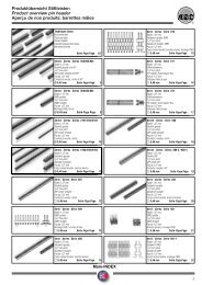
1.4 Board Layout<br />
1.4.1 Top Side<br />
COM3<br />
RS232<br />
DIMM1<br />
DIMM2<br />
COM4<br />
RS232<br />
JP7<br />
JP6<br />
Primary IDE<br />
JP3<br />
JP2<br />
digital LCD Sound<br />
Backlight<br />
USB1/2<br />
Floppy<br />
USB3<br />
USB4<br />
LPT<br />
VIA<br />
VT8606<br />
Battery<br />
Ethernet1<br />
RJ45<br />
JP5<br />
COM1<br />
RS232<br />
Reset<br />
Buzzer<br />
JP4<br />
Northbridge<br />
with integrated<br />
PROSavage4 AGP 4x<br />
Graphics<br />
Ethernet2<br />
RJ45<br />
Socket<br />
370<br />
12<br />
VIA<br />
VT82C686B<br />
JP1<br />
CRT-Monitor<br />
COM2<br />
RS232/422/482/IrDA<br />
Southbridge<br />
System Header<br />
A1<br />
PC/104<br />
PS/2<br />
Keyb./Mouse<br />
JP12 JP11<br />
JP9<br />
JP8<br />
Aux. Power<br />
Fan1 Fan2<br />
JP10
PISA-<strong>PIII</strong>-<strong>TwisterT</strong> User's Manual Installation<br />
1.4.2 Bottom Side<br />
Compact Flash<br />
Socket<br />
13<br />
LJP4<br />
LJP3<br />
LJP1 LJP2<br />
LVDS<br />
Connector
PISA-<strong>PIII</strong>-<strong>TwisterT</strong> User's Manual Installation<br />
2 Installation<br />
DIMM1<br />
DIMM2<br />
Battery<br />
Reset<br />
System Header<br />
JP1<br />
Fan2 Fan1<br />
2.1 CPU<br />
Aux. Power<br />
digital LCD<br />
Socket<br />
370<br />
A1<br />
Sound<br />
Backlight<br />
JP3<br />
JP2<br />
VIA<br />
VT8606<br />
Northbridge<br />
with integrated<br />
PROSavage4 AGP 4x<br />
Graphics<br />
JP8<br />
VIA<br />
VT82C686B<br />
Southbridge<br />
JP9<br />
14<br />
Primary IDE<br />
COM1<br />
RS232<br />
LPT<br />
PC/104<br />
Floppy<br />
JP4<br />
Buzzer<br />
JP5<br />
JP10<br />
JP6<br />
USB3<br />
USB4<br />
JP12<br />
JP11<br />
JP7<br />
COM2<br />
RS232/422/482/IrDA<br />
COM3<br />
RS232<br />
COM4<br />
RS232<br />
USB1/2<br />
Ethernet1<br />
RJ45<br />
Ethernet2<br />
RJ45<br />
The PISA-<strong>PIII</strong>-<strong>TwisterT</strong> supports Socket 370 Intel Pentium III and Celeron (both Tualatin Cores<br />
only) as well as VIA C3 CPUs.<br />
It is based on the VIA ProSavage PN133T chipset VT8606 (<strong>TwisterT</strong>) northbridge and VT82686B<br />
southbridge operating at 100 MHz or 133 MHz front side bus.<br />
The system performance depends on the CPU you choose.<br />
The following table shows the supported CPU types and their recommended jumper settings:<br />
CPU / internal frequency / L2-cache / core voltage JP1 JP2 JP3 JP4<br />
INTEL Celeron / 1000 / 256 / 100 /1.5 2 – 3 closed 2 – 3 1 – 2<br />
INTEL Celeron / 1100 / 256 / 100 /1.5 2 – 3 closed 2 – 3 1 – 2<br />
INTEL Celeron / 1200 / 256 / 100 /1.5 2 – 3 closed 2 – 3 1 – 2<br />
INTEL Celeron / 1400 / 256 / 100 /1.5 2 – 3 closed 2 – 3 1 – 2<br />
INTEL Pentium III / 1133 / 512 / 133 /1.45 2 – 3 closed 2 – 3 2 – 3<br />
INTEL Pentium III / 1200 / 512 / 133 /1.45 2 – 3 closed 2 – 3 2 – 3<br />
INTEL Pentium III / 1266 / 512 / 133 /1.45 2 – 3 closed 2 – 3 2 – 3<br />
VIA C3 Ezra / 800 / 64 / 133 / 1.35 1 – 2 open 1 – 2 2 – 3<br />
VIA C3 Ezra / 1000 / 64 / 133 / 1.35 1 – 2 open 1 – 2 2 – 3<br />
VIA C3 Ezra-T / 1000 / 64 / 100 / 1.45 2 – 3 closed 2 – 3 1 – 2<br />
VIA C3 Nehemiah / 1000 / 64 / 133 / 1.40 2 – 3 closed 2 – 3 2 – 3<br />
VIA C3 Nehemiah / 1000 / 64 / 133 / 1.45 2 – 3 closed 2 – 3 2 – 3<br />
Note:<br />
� Intel CPUs have 32 Kbyte L1-caches<br />
� VIA C3 CPUs have 128 Kbyte L1-caches.<br />
� Do not run any CPU without an adequate fan and heatsink!<br />
CRT-Monitor<br />
PS/2<br />
Keyb./Mouse
PISA-<strong>PIII</strong>-<strong>TwisterT</strong> User's Manual Installation<br />
2.2 SDRAM<br />
DIMM1<br />
DIMM2<br />
Battery<br />
Reset<br />
System Header<br />
JP1<br />
Fan2 Fan1<br />
Aux. Power<br />
digital LCD<br />
Socket<br />
370<br />
A1<br />
Sound<br />
Backlight<br />
JP3<br />
JP2<br />
VIA<br />
VT8606<br />
Northbridge<br />
with integrated<br />
PROSavage4 AGP 4x<br />
Graphics<br />
JP8<br />
VIA<br />
VT82C686B<br />
Southbridge<br />
JP9<br />
15<br />
Primary IDE<br />
COM1<br />
RS232<br />
LPT<br />
PC/104<br />
Floppy<br />
JP4<br />
Buzzer<br />
JP5<br />
JP10<br />
JP6<br />
USB3<br />
USB4<br />
JP12<br />
JP11<br />
JP7<br />
COM2<br />
RS232/422/482/IrDA<br />
COM3<br />
RS232<br />
COM4<br />
RS232<br />
USB1/2<br />
Ethernet1<br />
RJ45<br />
Ethernet2<br />
RJ45<br />
The PISA-<strong>PIII</strong>-<strong>TwisterT</strong> board has two DIMM sockets for standard 3,3V SDRAM DIMM modules.<br />
The advanced memory controller supports 256 Mbit DRAM technology thus supporting up to 512<br />
Mbyte per bank or 1 Gbyte in one DIMM socket.<br />
The following table shows the SDRAM organizations which are supported:<br />
Organization Capacity Module max. Capacity (2 DIMMs)<br />
4M x 64 32 MByte single or double sided 64 MByte<br />
8M x 64 64 MByte single or double sided 128 MByte<br />
16M x 64 128 MByte single or double sided 256 MByte<br />
32M x 64 256 MByte single or double sided 512 MByte<br />
64M x 64 512 MByte single or double sided 1 GByte<br />
128M x 64 1 GByte double sided 2 GByte<br />
Notes:<br />
� The DRAM controller supports PC133 and PC100 memory modules. The memory<br />
timing is installed automatically by the BIOS according to the SPD information read from<br />
the serial E 2 PROM on the module. SDRAM clock speed is independent of the selected<br />
speed of the CPUs front side bus. If PC133 and PC100 memory modules are mixed on<br />
the board, the timing parameters of the slower module will be installed.<br />
� PC66 memory modules are not supported.<br />
CRT-Monitor<br />
PS/2<br />
Keyb./Mouse
PISA-<strong>PIII</strong>-<strong>TwisterT</strong> User's Manual Installation<br />
DIMM1<br />
DIMM2<br />
Battery<br />
Reset<br />
System Header<br />
JP1<br />
Fan2 Fan1<br />
Aux. Power<br />
digital LCD<br />
Socket<br />
370<br />
2.3 PCI I/O Voltage<br />
A1<br />
Sound<br />
Backlight<br />
JP3<br />
JP2<br />
VIA<br />
VT8606<br />
Northbridge<br />
with integrated<br />
PROSavage4 AGP 4x<br />
Graphics<br />
JP8<br />
VIA<br />
VT82C686B<br />
Southbridge<br />
JP9<br />
16<br />
Primary IDE<br />
COM1<br />
RS232<br />
LPT<br />
PC/104<br />
Floppy<br />
JP4<br />
Buzzer<br />
Jumper JP12 selects the PCI-I/O voltage for the PISA board.<br />
JP5<br />
JP10<br />
JP6<br />
USB3<br />
USB4<br />
JP12<br />
JP11<br />
JP7<br />
COM2<br />
RS232/422/482/IrDA<br />
COM3<br />
RS232<br />
COM4<br />
RS232<br />
USB1/2<br />
Ethernet1<br />
RJ45<br />
Ethernet2<br />
RJ45<br />
JP12 Function<br />
open Factory default setting.<br />
The PISA board is installed in a backplane which connects the VCCIO<br />
pin of the PISA slot to the VCCIO pins of the PCI slots.<br />
1 –2 The PISA board is installed in a backplane with 5V PCI slots and the<br />
VCCIO pin of the PISA slot is not connected to the VCCIO pin of any<br />
PCI slot.<br />
2 - 3 The PISA board is installed in a backplane with 3.3V PCI slots and the<br />
VCCIO pin of the PISA slot is not connected to the VCCIO pin of any<br />
PCI slot.<br />
Or<br />
the PISA board is used without a backplane.<br />
� Take care about correct setting of jumper JP12 if the PISA-<strong>PIII</strong>-<strong>TwisterT</strong> board is<br />
installed in a backplane. Wrong settings may damage the board and the<br />
backplane.<br />
CRT-Monitor<br />
PS/2<br />
Keyb./Mouse
PISA-<strong>PIII</strong>-<strong>TwisterT</strong> User's Manual Installation<br />
DIMM1<br />
DIMM2<br />
Battery<br />
Reset<br />
System Header<br />
JP1<br />
Fan2 Fan1<br />
Aux. Power<br />
digital LCD<br />
Socket<br />
370<br />
A1<br />
Sound<br />
Backlight<br />
JP3<br />
JP2<br />
VIA<br />
VT8606<br />
Northbridge<br />
with integrated<br />
PROSavage4 AGP 4x<br />
Graphics<br />
JP8<br />
VIA<br />
VT82C686B<br />
Southbridge<br />
JP9<br />
17<br />
Primary IDE<br />
COM1<br />
RS232<br />
LPT<br />
PC/104<br />
Floppy<br />
JP4<br />
Buzzer<br />
JP5<br />
JP10<br />
JP6<br />
USB3<br />
USB4<br />
JP12<br />
JP11<br />
JP7<br />
COM2<br />
RS232/422/482/IrDA<br />
COM3<br />
RS232<br />
COM4<br />
RS232<br />
USB1/2<br />
Ethernet1<br />
RJ45<br />
Ethernet2<br />
RJ45<br />
2.4 Clear CMOS Data and BIOS Flash Recovery Jumper<br />
JP8 Clear CMOS Data JP9 BIOS Flash Recovery<br />
1 – 2 Normal operation open Normal operation<br />
2 - 3 Clear CMOS data closed Flash programming<br />
open No operation<br />
Note:<br />
� For BIOS flash recovery operation JP9 has to be closed before power-up and<br />
the crises recovery disk has to be installed in floppy drive A>.<br />
� To clear the contents of the CMOS (setup configuration) the following procedure<br />
has to be done :<br />
1. Switch off power.<br />
2. Install jumper at position 2 – 3 for a few seconds.<br />
3. Install jumper again at position 1 – 2.<br />
2.5 COM1, COM3 and COM4 (RS232)<br />
DCD# DSR#<br />
RXD RTS#<br />
TXD CTS#<br />
DTR# RI#<br />
GND Not connected<br />
CRT-Monitor<br />
PS/2<br />
Keyb./Mouse
PISA-<strong>PIII</strong>-<strong>TwisterT</strong> User's Manual Installation<br />
DIMM1<br />
DIMM2<br />
Battery<br />
Reset<br />
System Header<br />
JP1<br />
Fan2 Fan1<br />
Aux. Power<br />
digital LCD<br />
Socket<br />
370<br />
Sound<br />
Backlight<br />
JP3<br />
JP2<br />
VIA<br />
VT8606<br />
Northbridge<br />
with integrated<br />
PROSavage4 AGP 4x<br />
Graphics<br />
JP8<br />
VIA<br />
VT82C686B<br />
Southbridge<br />
2.6 COM2 (RS232/422/485, IrDA)<br />
A1<br />
JP9<br />
18<br />
Primary IDE<br />
COM1<br />
RS232<br />
LPT<br />
PC/104<br />
Floppy<br />
JP4<br />
Buzzer<br />
JP5<br />
JP10<br />
JP6<br />
USB3<br />
USB4<br />
JP12<br />
JP11<br />
JP7<br />
COM2<br />
RS232/422/482/IrDA<br />
COM3<br />
RS232<br />
COM4<br />
RS232<br />
USB1/2<br />
Ethernet1<br />
RJ45<br />
Ethernet2<br />
RJ45<br />
COM2 can be used in RS232, RS422 or RS485 mode. The basic configuration is done via SETUP.<br />
If RS485 mode is selected the signal DTR controls the transmitter, the polarity is determined by<br />
JP10.<br />
In RS422 or RS485 mode a 100Ω differential termination resistor may be enabled by JP11.<br />
JP10 Function JP11 Function<br />
1 – 2 DTR low = transmit, DTR high = receive open Termination resistor disabled<br />
2 – 3 DTR high = transmit, DTR low = receive closed Termination resistor enabled<br />
open No function; do not leave open.<br />
Connector COM2<br />
DCD# DSR#<br />
RXD RTS#<br />
TXD CTS#<br />
DTR# RI#<br />
GND Not connected<br />
RS422 TXD+ / RS485 Data+ RS422 TXD- / RS485 Data-<br />
RS422 RXD+ RS422 RXD-<br />
GND + 5V<br />
IrDA IRRX IrDA IRTX<br />
Not connected Not connected<br />
CRT-Monitor<br />
PS/2<br />
Keyb./Mouse
PISA-<strong>PIII</strong>-<strong>TwisterT</strong> User's Manual Installation<br />
DIMM1<br />
DIMM2<br />
Battery<br />
Reset<br />
System Header<br />
JP1<br />
Fan2 Fan1<br />
Aux. Power<br />
digital LCD<br />
Socket<br />
370<br />
2.7 LCD Interfaces<br />
A1<br />
Sound<br />
Backlight<br />
JP3<br />
JP2<br />
VIA<br />
VT8606<br />
Northbridge<br />
with integrated<br />
PROSavage4 AGP 4x<br />
Graphics<br />
JP8<br />
VIA<br />
VT82C686B<br />
Southbridge<br />
JP9<br />
19<br />
Primary IDE<br />
COM1<br />
RS232<br />
LPT<br />
Floppy<br />
JP4<br />
Buzzer<br />
The LCD panel type (technology, resolution) can be selected via SETUP.<br />
JP6 selects the voltage level for panel power supply on both the 50-pin IDC header for digital flat<br />
panels and on the 40-pin FFC connector for LVDS panels.<br />
You have to set this jumper according to the type of LCD panel you want to use.<br />
JP7 selects if the display power on the connectors should be permanently on, or switched on an off<br />
by the panel power sequencing signal ENVDD.<br />
PC/104<br />
JP5<br />
JP10<br />
JP6<br />
USB3<br />
USB4<br />
JP12<br />
JP11<br />
JP7<br />
COM2<br />
RS232/422/482/IrDA<br />
COM3<br />
RS232<br />
COM4<br />
RS232<br />
USB1/2<br />
Ethernet1<br />
RJ45<br />
Ethernet2<br />
RJ45<br />
Jumpers<br />
JP6 LCD Power Level JP7 LCD Power Mode<br />
1 – 2 + 3.3 Volt 1 – 2 always on<br />
2 – 3 + 5 Volt 2 – 3 switched with ENVDD<br />
open Open circuit open No operation, don’t use<br />
Backlight Power (header, 6 pins, 2.54 mm)<br />
+ 12V<br />
+ 5V<br />
GND<br />
GND<br />
+ 5V<br />
+ 12V<br />
LVDS<br />
CRT-Monitor<br />
PS/2<br />
Keyb./Mouse
PISA-<strong>PIII</strong>-<strong>TwisterT</strong> User's Manual Installation<br />
2.7.1 LCD Connectors<br />
Digital (IDC header, 50 pins, 2.0 mm)<br />
+12V 1 2 +12V<br />
GND 3 4 GND<br />
+5V / +3V 5 6 +5V / +3V<br />
ENVEE 7 8 GND<br />
P0 9 10 P1<br />
P2 11 12 P3<br />
P4 13 14 P5<br />
P6 15 16 P7<br />
P8 17 18 P9<br />
P10 19 20 P11<br />
P12 21 22 P13<br />
P14 23 24 P15<br />
P16 25 26 P17<br />
P18 27 28 P19<br />
P20 29 30 P21<br />
P22 31 32 P23<br />
P24 33 34 P25<br />
SHFTCLK 35 36 FLM (VSYNC)<br />
M (DE) 37 38 LP (HSYNC)<br />
GND 39 40 ENBLIGHT<br />
P26 41 42 P27<br />
P28 43 44 P29<br />
P30 45 46 P31<br />
P32 47 48 P33<br />
P34 49 50 P35<br />
20<br />
LVDS (FCC connector, 40 pins, 0.5 mm)<br />
N.C. 1<br />
CH1_RED+ 2<br />
CH1_RED - 3<br />
ENVEE 4<br />
CH1_GRN+ 5<br />
CH1_GRN - 6<br />
N.C. 7<br />
CH1_BLUE+ 8<br />
CH1_BLUE - 9<br />
GND 10<br />
CH1_CLK+ 11<br />
CH1_CLK - 12<br />
GND 13<br />
N.C. 14<br />
N.C. 15<br />
PDC_DATA 16<br />
CH2_RED+ 17<br />
CH2_RED - 18<br />
PDC_CLK 19<br />
CH2_GRN+ 20<br />
CH2_GRN - 21<br />
DETECT# 22<br />
CH2_BLUE+ 23<br />
CH2_BLUE - 24<br />
GND 25<br />
CH2_CLK+ 26<br />
CH2_CLK - 27<br />
GND 28<br />
N.C. 29<br />
N.C. 30<br />
+5V / +3V 31<br />
+5V / +3V 32<br />
+5V / +3V 33<br />
+5V / +3V 34<br />
ENBLIGHT# 35<br />
GND 36<br />
GND 37<br />
+12V 38<br />
+12V 39<br />
+12V 40<br />
Note: The FCC connector for LVDS uses bottom contacts. Turn flat foil<br />
cable contact side top down for insertion.
PISA-<strong>PIII</strong>-<strong>TwisterT</strong> User's Manual Installation<br />
2.7.2 Digital Display Data Mapping<br />
Signal Pin# DSTN16 DSTN24 TFT18 TFT24 TFT2x18<br />
P0 9 — LB3 — B0 R00<br />
P1 10 — LB2 — B1 R10<br />
P2 11 LB1 LB1 B0 B2 R01<br />
P3 12 LB0 LB0 B1 B3 R11<br />
P4 13 — UB3 B2 B4 R02<br />
P5 14 — UB2 B3 B5 R12<br />
P6 15 UB1 UB1 B4 B6 R03<br />
P7 16 UB0 UB0 B5 B7 R13<br />
P8 17 — LG3 — G0 R14<br />
P9 18 LG2 LG2 — G1 R14<br />
P10 19 LG1 LG1 G0 G2 R05<br />
P11 20 LG0 LG0 G1 G3 R15<br />
P12 21 — UG3 G2 G4 G00<br />
P13 22 UG2 UG2 G3 G5 G10<br />
P14 23 UG1 UG1 G4 G6 G01<br />
P15 24 UG0 UG0 G5 G7 G11<br />
P16 25 — LR3 — R0 G02<br />
P17 26 LR2 LR2 — R1 G12<br />
P18 27 LR1 LR1 R0 R2 G03<br />
P19 28 LR0 LR0 R1 R3 G13<br />
P20 29 UR3 R2 R4 G04<br />
P21 30 UR2 UR2 R3 R5 G14<br />
P22 31 UR1 UR1 R4 R6 G05<br />
P23 32 UR0 UR0 R5 R7 G15<br />
P24 33 — — — — B00<br />
P25 34 — — — — B10<br />
P26 41 — — — — B01<br />
P27 42 — — — — B11<br />
P28 43 — — — — B02<br />
P29 44 — — — — B12<br />
P30 45 — — — — B03<br />
P31 46 — — — — B13<br />
P32 47 — — — — B04<br />
P33 48 — — — — B14<br />
P34 49 — — — — B05<br />
P35 50 — — — — B15<br />
21
PISA-<strong>PIII</strong>-<strong>TwisterT</strong> User's Manual Installation<br />
DIMM1<br />
DIMM2<br />
Battery<br />
Reset<br />
System Header<br />
JP1<br />
Fan2 Fan1<br />
Aux. Power<br />
digital LCD<br />
Socket<br />
370<br />
A1<br />
Sound<br />
Backlight<br />
JP3<br />
JP2<br />
VIA<br />
VT8606<br />
Northbridge<br />
with integrated<br />
PROSavage4 AGP 4x<br />
Graphics<br />
JP8<br />
VIA<br />
VT82C686B<br />
Southbridge<br />
JP9<br />
22<br />
Primary IDE<br />
COM1<br />
RS232<br />
LPT<br />
PC/104<br />
Floppy<br />
JP4<br />
Buzzer<br />
JP5<br />
JP10<br />
JP6<br />
USB3<br />
USB4<br />
JP12<br />
JP11<br />
JP7<br />
COM2<br />
RS232/422/482/IrDA<br />
COM3<br />
RS232<br />
COM4<br />
RS232<br />
USB1/2<br />
Ethernet1<br />
RJ45<br />
Ethernet2<br />
RJ45<br />
2.8 AUX Power Connector<br />
The PISA-<strong>PIII</strong>-<strong>TwisterT</strong> board has a 4-pin power connector like standard hard disks have.<br />
This connector may be used to power the board if it is used as a stand-alone system without<br />
additional ISA- or PCI-cards on a backplane.<br />
+ 12V<br />
GND<br />
GND<br />
+ 5V<br />
Note: Square marked pin on solder side is pin # 4 (+5V) , not pin #1 (+12V).<br />
2.9 Fan Connectors<br />
Two Fans may be connected to the board.<br />
TACHO<br />
FAN Power<br />
GND<br />
Fan power can be selected by solder jumpers LJP1 and LJP2 on the solder side of the PISA-<strong>PIII</strong>-<br />
<strong>TwisterT</strong> board.<br />
Power select FAN1<br />
Power select FAN2<br />
+12 V FAN power<br />
(factory default)<br />
+5 V FAN power<br />
CRT-Monitor<br />
PS/2<br />
Keyb./Mouse
PISA-<strong>PIII</strong>-<strong>TwisterT</strong> User's Manual Installation<br />
DIMM1<br />
DIMM2<br />
Battery<br />
Reset<br />
System Header<br />
JP1<br />
Fan2 Fan1<br />
Aux. Power<br />
digital LCD<br />
Socket<br />
370<br />
A1<br />
Sound<br />
Backlight<br />
JP3<br />
JP2<br />
VIA<br />
VT8606<br />
Northbridge<br />
with integrated<br />
PROSavage4 AGP 4x<br />
Graphics<br />
JP8<br />
VIA<br />
VT82C686B<br />
Southbridge<br />
23<br />
Primary IDE<br />
COM1<br />
RS232<br />
LPT<br />
Floppy<br />
JP4<br />
Buzzer<br />
2.10 Onboard Reset Switch<br />
The PISA-<strong>PIII</strong>-<strong>TwisterT</strong> board has an onboard switch to reset the system.<br />
2.11 System Header<br />
JP9<br />
PC/104<br />
JP5<br />
JP10<br />
JP6<br />
USB3<br />
USB4<br />
PWR_LED + 1 2 KEYB_CLK<br />
n.c. 3 4 KEYB_DAT<br />
PWR_LED - 5 6 n.c.<br />
n.c. 7 8 GND<br />
GND 9 10 + 5V<br />
+ 5 V 11 12 MOUSE_CLK<br />
I 2 C CLK 13 14 MOUSE_DAT<br />
I 2 C DAT 15 16 + 5V<br />
GND 17 18 n.c.<br />
HD_LED + 19 20 n.c.<br />
HD_LED - 21 22 SPEAKER<br />
EXT_RESET 23 24 GND EXT_RESET<br />
EXT_TEMP (2) 25 26 GND EXT_TEMP<br />
+ 5V_SB (ATX) (2) 27 28 PWRBTN# (ATX) (2)<br />
GND 29 30 PS_ON (ATX) (2)<br />
JP12<br />
JP11<br />
JP7<br />
COM2<br />
RS232/422/482/IrDA<br />
COM3<br />
RS232<br />
COM4<br />
RS232<br />
USB1/2<br />
Ethernet1<br />
RJ45<br />
Ethernet2<br />
RJ45<br />
Notes:<br />
(1) For temperature sensing connect a 10k NTC to EXT_TEMP and GND EXT_TEMP<br />
Reference: SEMITEC JT-Thermistor Type 103JT-025, B=3435K.<br />
(2) In order to use ATX extension of the PISA-<strong>PIII</strong>-<strong>TwisterT</strong> board connect the appropriate<br />
signals of an ATX power supply to these pins.<br />
CRT-Monitor<br />
PS/2<br />
Keyb./Mouse
PISA-<strong>PIII</strong>-<strong>TwisterT</strong> User's Manual Installation<br />
DIMM1<br />
DIMM2<br />
Battery<br />
Reset<br />
System Header<br />
JP1<br />
Fan2 Fan1<br />
Aux. Power<br />
digital LCD<br />
Socket<br />
370<br />
2.12 Onboard Buzzer<br />
Sound<br />
Backlight<br />
JP3<br />
JP2<br />
VIA<br />
VT8606<br />
Northbridge<br />
with integrated<br />
PROSavage4 AGP 4x<br />
Graphics<br />
JP8<br />
VIA<br />
VT82C686B<br />
Southbridge<br />
The onboard buzzer can be enabled by jumper JP5.<br />
A1<br />
JP5 Buzzer<br />
closed enabled<br />
open dsiabled<br />
2.13 Onboard Sound<br />
JP9<br />
24<br />
Primary IDE<br />
COM1<br />
RS232<br />
LPT<br />
PC/104<br />
Floppy<br />
JP4<br />
Buzzer<br />
JP5<br />
JP10<br />
JP6<br />
USB3<br />
USB4<br />
LINE IN LEFT 1 2 CD IN LEFT<br />
AGND 3 4 CD GND<br />
AGND 5 6 CD GND<br />
LINE IN RIGHT 7 8 CD IN RIGHT<br />
MIC IN 9 10 SOUND LEFT<br />
AGND 11 12 AGND<br />
MIC VCC 13 14 SOUND RIGHT<br />
� SOUND LEFT and SOUND RIGHT have no additional amplifiers.<br />
Do only connect active speakers to these outputs.<br />
JP12<br />
JP11<br />
JP7<br />
COM2<br />
RS232/422/482/IrDA<br />
COM3<br />
RS232<br />
COM4<br />
RS232<br />
USB1/2<br />
Ethernet1<br />
RJ45<br />
Ethernet2<br />
RJ45<br />
CRT-Monitor<br />
PS/2<br />
Keyb./Mouse
PISA-<strong>PIII</strong>-<strong>TwisterT</strong> User's Manual Installation<br />
DIMM1<br />
DIMM2<br />
Battery<br />
Reset<br />
System Header<br />
JP1<br />
Fan2 Fan1<br />
Aux. Power<br />
digital LCD<br />
Socket<br />
370<br />
2.14 EIDE<br />
2.14.1 Primary Channel<br />
A1<br />
Sound<br />
Backlight<br />
JP3<br />
JP2<br />
VIA<br />
VT8606<br />
Northbridge<br />
with integrated<br />
PROSavage4 AGP 4x<br />
Graphics<br />
JP8<br />
VIA<br />
VT82C686B<br />
Southbridge<br />
JP9<br />
25<br />
Primary IDE<br />
COM1<br />
RS232<br />
LPT<br />
PC/104<br />
Floppy<br />
JP4<br />
Buzzer<br />
JP5<br />
JP10<br />
JP6<br />
USB3<br />
USB4<br />
JP12<br />
JP11<br />
JP7<br />
COM2<br />
RS232/422/482/IrDA<br />
COM3<br />
RS232<br />
COM4<br />
RS232<br />
USB1/2<br />
Ethernet1<br />
RJ45<br />
Ethernet2<br />
RJ45<br />
RESET# 1 2 GND<br />
DATA7 3 4 DATA<br />
DATA6 5 6 DATA9<br />
DATA5 7 8 DATA10<br />
DATA4 9 10 DATA11<br />
DATA3 11 12 DATA12<br />
DATA2 13 14 DATA13<br />
DATA1 15 16 DATA14<br />
DATA0 17 18 DATA15<br />
GND 19 20 KEY (missing pin)<br />
DRQ0 21 22 GND<br />
IOW# 23 24 GND<br />
IOR# 25 26 GND<br />
IORDY 27 28 CSEL#<br />
DAK0# 29 30 GND<br />
IRQ14 31 32 n.c.<br />
ADR1 33 34 CBLID#<br />
ADR0 35 36 ADR2<br />
CS0# 37 38 CS1#<br />
ACTIV# 39 40 GND<br />
CRT-Monitor<br />
PS/2<br />
Keyb./Mouse
PISA-<strong>PIII</strong>-<strong>TwisterT</strong> User's Manual Installation<br />
LVDS<br />
LCD Connector<br />
Compact Flash<br />
Socket<br />
26<br />
LJP2 LJP1<br />
LJP3<br />
LJP4<br />
2.14.2 Secondary Channel (optionally), CompactFlash<br />
Pin Name Pin Name Pin Name Pin Name Pin Name<br />
1 GND 11 GND 21 DATA0 31 DATA15 41 RESET#<br />
2 DATA3 12 GND 22 DATA1 32 CS3# 42 IORDY<br />
3 DATA4 13 + 5 V 23 DATA2 33 GND 43 n.c.<br />
4 DATA5 14 GND 24 n.c. 34 IOR# 44 + 5 V<br />
5 DATA6 15 GND 25 n.c. 35 IOW# 45 ACTIVE#<br />
6 DATA7 16 GND 26 n.c. 36 n.c. 46 n.c.<br />
7 CS1# 17 GND 27 DATA11 37 IRQ15 47 DATA8<br />
8 GND 18 A2 28 DATA12 38 + 5 V 48 DATA9<br />
9 GND 19 A1 29 DATA13 39 Pulldown 49 DATA10<br />
10 GND 20 A0 30 DATA14 40 n.c. 50 GND<br />
Optionally a CompactFlash socket can be mounted onto the solder side of the PISA-<strong>PIII</strong>-<br />
<strong>TwisterT</strong> board.<br />
Note:<br />
� CompactFlash cards are IDE compatible and therefore no special Flash driver or a<br />
Flash file system is needed. Capacities for CompactFlash range from 8 Mbyte to 2<br />
Gbyte. The CompactFlash socket is routed to the IDE secondary channel.
PISA-<strong>PIII</strong>-<strong>TwisterT</strong> User's Manual Installation<br />
DIMM1<br />
DIMM2<br />
Battery<br />
Reset<br />
System Header<br />
JP1<br />
Fan2 Fan1<br />
Aux. Power<br />
digital LCD<br />
Socket<br />
370<br />
2.15 Floppy Disk<br />
Sound<br />
Backlight<br />
JP3<br />
JP2<br />
VIA<br />
VT8606<br />
Northbridge<br />
with integrated<br />
PROSavage4 AGP 4x<br />
Graphics<br />
JP8<br />
VIA<br />
VT82C686B<br />
Southbridge<br />
GND 1 2 DENSEL#<br />
GND 3 4 n.c.<br />
GND 5 6 n.c.<br />
GND 7 8 INDEX#<br />
GND 9 10 MTR0#<br />
GND 11 12 DRVSEL1#<br />
GND 13 14 DRVSEL0#<br />
GND 15 16 MTR1#<br />
GND 17 18 DIR#<br />
GND 19 20 STEP#<br />
GND 21 22 WDATA#<br />
GND 23 24 WGATE#<br />
GND 25 26 TRK0#<br />
GND 27 28 WPROT#<br />
GND 29 30 RDATA#<br />
GND 31 32 HEADSEL<br />
GND 33 34 DSKCHG#<br />
2.17 Internal USB<br />
A1<br />
JP9<br />
27<br />
Primary IDE<br />
COM1<br />
RS232<br />
LPT<br />
PC/104<br />
Floppy<br />
JP4<br />
Buzzer<br />
+5V 1 2 +5V<br />
DATA2 - 3 4 DATA3 -<br />
DATA2+ 5 6 DATA3+<br />
GND 7 8 GND<br />
SHIELD 9 10 SHIELD<br />
JP5<br />
JP10<br />
JP6<br />
USB3<br />
USB4<br />
JP12<br />
JP11<br />
JP7<br />
COM2<br />
RS232/422/482/IrDA<br />
COM3<br />
RS232<br />
COM4<br />
RS232<br />
USB1/2<br />
Ethernet1<br />
RJ45<br />
Ethernet2<br />
RJ45<br />
CRT-Monitor<br />
PS/2<br />
Keyb./Mouse<br />
2.16 Parallel Port<br />
STB# 1 2 AFD#<br />
D0 3 4 ERR#<br />
D1 5 6 INIT#<br />
D2 7 8 SLIN#<br />
D3 9 10 GND<br />
D4 11 12 GND<br />
D5 13 14 GND<br />
D6 15 16 GND<br />
D7 17 18 GND<br />
ACK# 19 20 GND<br />
BUSY# 21 22 GND<br />
PE 23 24 GND<br />
SLCT# 25 26 GND
PISA-<strong>PIII</strong>-<strong>TwisterT</strong> User's Manual Installation<br />
DIMM1<br />
DIMM2<br />
Battery<br />
Reset<br />
System Header<br />
JP1<br />
Fan2 Fan1<br />
Aux. Power<br />
digital LCD<br />
Socket<br />
370<br />
2.18 External USB<br />
2.19 RJ45 (Ethernet)<br />
Link LED<br />
A1<br />
Sound<br />
Backlight<br />
EMI Shield<br />
JP3<br />
JP2<br />
VIA<br />
VT8606<br />
Northbridge<br />
with integrated<br />
PROSavage4 AGP 4x<br />
Graphics<br />
JP8<br />
VIA<br />
VT82C686B<br />
Southbridge<br />
JP9<br />
28<br />
Primary IDE<br />
COM1<br />
RS232<br />
LPT<br />
PC/104<br />
Floppy<br />
JP4<br />
Buzzer<br />
+5V DATA0 - DATA0+ GND<br />
+5V DATA1 - DATA1+ GND<br />
RX - RX+ TX - TX+<br />
The second Ethernet controller is available as an option.<br />
JP5<br />
JP10<br />
JP6<br />
USB3<br />
USB4<br />
JP12<br />
JP11<br />
JP7<br />
COM2<br />
RS232/422/482/IrDA<br />
COM3<br />
RS232<br />
COM4<br />
RS232<br />
USB1/2<br />
Ethernet1<br />
RJ45<br />
Ethernet2<br />
RJ45<br />
Speed LED<br />
CRT-Monitor<br />
PS/2<br />
Keyb./Mouse
PISA-<strong>PIII</strong>-<strong>TwisterT</strong> User's Manual Installation<br />
DIMM1<br />
DIMM2<br />
Battery<br />
Reset<br />
System Header<br />
JP1<br />
Fan2 Fan1<br />
2.20 CRT<br />
Aux. Power<br />
digital LCD<br />
Socket<br />
370<br />
A1<br />
Sound<br />
Backlight<br />
JP3<br />
JP2<br />
VIA<br />
VT8606<br />
Northbridge<br />
with integrated<br />
PROSavage4 AGP 4x<br />
Graphics<br />
JP8<br />
VIA<br />
VT82C686B<br />
Southbridge<br />
JP9<br />
29<br />
Primary IDE<br />
COM1<br />
RS232<br />
LPT<br />
PC/104<br />
Floppy<br />
JP4<br />
Buzzer<br />
JP5<br />
JP10<br />
JP6<br />
USB3<br />
USB4<br />
JP12<br />
JP11<br />
JP7<br />
COM2<br />
RS232/422/482/IrDA<br />
COM3<br />
RS232<br />
COM4<br />
RS232<br />
USB1/2<br />
Ethernet1<br />
RJ45<br />
Ethernet2<br />
RJ45<br />
RED 1 9 DDC VCC<br />
GREEN 2 10 GND SYNC<br />
BLUE 3 11 reserved<br />
reserved 4 12 DDC SDA<br />
GND 5 13 HSYNC<br />
GND RED 6 14 VSYNC<br />
GND GREEN 7 15 DDC CLK<br />
GND BLUE 8<br />
2.21 Keyboard / Mouse Mini-DIN Connector<br />
M_CLK KB_CLK<br />
+ 5V GND<br />
MDATA KB_CLK<br />
Note:<br />
� A standard PS/2-keybord may be connected directly.<br />
� In order to use a mouse or both keyboard and mouse an Y-adapter is needed.<br />
CRT-Monitor<br />
PS/2<br />
Keyb./Mouse
PISA-<strong>PIII</strong>-<strong>TwisterT</strong> User's Manual Installation<br />
2.22 PISA Edge-Connector<br />
Pin ISA Bus Top Layer ISA Bus Bottom Layer PCI Bus Top Layer PCI Bus Bottom Layer<br />
1 IOCHCK# GND GND GND<br />
2 SD7 RESETDRV GND GND<br />
3 SD6 +5V INTB# INTA#<br />
4 SD5 IRQ9 INTD# INTC#<br />
5 SD4 -5V +5V +5V<br />
6 SD3 DRQ2<br />
7 SD2 -12V +5V V I/O<br />
8 SD1 0WS# PCIRST# PCICLK2<br />
9 SD0 +12V GNT0# GND<br />
10 IOCHRDY GND REQ0# GNT1#<br />
11 AEN SMEMW# GND GND<br />
12 SA19 SMEMR# PCICLK1 REQ1#<br />
13 SA18 IOWC# GND AD31<br />
14 SA17 IORC# AD30 AD29<br />
15 SA16 DACK3# REQ2# PCICLK3<br />
16 SA15 DRQ3<br />
17 SA14 DACK1# GNT2# PCICLK4<br />
18 SA13 DRQ1 AD28 AD27<br />
19 SA12 REFSH# AD26 AD25<br />
20 SA11 SYSCLK AD24 CBE3#<br />
21 SA10 IRQ7 AD22 AD23<br />
22 SA9 IRQ6 AD20 AD21<br />
23 SA8 IRQ5 AD18 AD19<br />
24 SA7 IRQ4 PWRGDIN REQ3#<br />
25 SA6 IRQ3<br />
26 SA5 DACK2# GND GNT3#<br />
27 SA4 TC AD16 AD17<br />
28 SA3 BALE FRAME# IRDY#<br />
29 SA2 +5V CBE2# DEVSEL#<br />
30 SA1 OSC TRDY# LOCK#<br />
31 SA0 GND STOP# PERR#<br />
32<br />
33 GND SERR#<br />
34 AD15<br />
35 SBHE# MEMCS16# CBE1# AD14<br />
36 LA23 IOCS16# PAR AD12<br />
37 LA22 IRQ10 GND GND<br />
38 LA21 IRQ11<br />
39 LA20 IRQ12 GND M66EN<br />
40 LA19 IRQ15 AD13 AD10<br />
41 LA18 IRQ14 AD11 AD8<br />
42 LA17 DACK0# AD9 AD7<br />
43 MEMR# DRQ0 CBE0# AD5<br />
44 MEMW# DACK5# AD6 AD3<br />
45 SD8 DRQ5 AD4 AD1<br />
46 SD9 DACK6# AD2 AD0<br />
47 SD10 DRQ6<br />
48 SD11 DACK7# +5V V I/O<br />
49 SD12 DRQ7 +5V +5V<br />
50 SD13 +5V GND GND<br />
51 SD14 MASTER# GND GND<br />
52 SD15 GND<br />
30
PISA-<strong>PIII</strong>-<strong>TwisterT</strong> User's Manual Installation<br />
2.23 PC/104 Conncetor<br />
Pin A B C D<br />
0 — — GND GND<br />
1 IOCHCK# GND SBHE# MEMS16#<br />
2 SD7 RESET LA23 IOCS16#<br />
3 SD6 +5V LA22 IRQ10<br />
4 SD5 IRQ9 LA21 IRQ11<br />
5 SD4 MEMR# LA20 IRQ12<br />
6 SD3 DRQ2 LA19 IRQ15<br />
7 SD2 -12V LA18 IRQ14<br />
8 SD1 0WS LA17 DACK0#<br />
9 SD0 +12V MRDC# DRQ0<br />
10 IOCHRDY GND MWTC# DACK5#<br />
11 AEN SMEMW# SD8 DRQ5<br />
12 SA19 SMEMR# SD9 DACK6#<br />
13 SA18 /IOWC# SD10 DRQ6<br />
14 SA17 IORC# SD11 DACK7#<br />
15 SA16 DACK3# SD12 DRQ7<br />
16 SA15 DRQ3 SD13 +5 V<br />
17 SA14 DACK1# SD14 MASTER#<br />
18 SA13 DRQ1 SD15 GND<br />
19 SA12 REFSH# KEY GND<br />
20 SA11 SYSCLK — —<br />
21 SA10 IRQ7 — —<br />
22 SA9 IRQ6 — —<br />
23 SA8 IRQ5 — —<br />
24 SA7 IRQ4 — —<br />
25 SA6 IRQ3 — —<br />
26 SA5 DACK2# — —<br />
27 SA4 TC — —<br />
28 SA3 BALE — —<br />
29 SA2 +5V — —<br />
30 SA1 OSC — —<br />
31 SA0 MEMW# — —<br />
32 GND GND — —<br />
31
PISA-<strong>PIII</strong>-<strong>TwisterT</strong> User's Manual Installation<br />
2.24 Watchdog<br />
The watchdog can be enabled via SETUP and the user can define if the counter should start<br />
during system boot or later by an application software.<br />
It has a programmable delay timer which expires once before the watchdog timer begins counting.<br />
After the programmable timeout counter has expired a system reset will be generated.<br />
If enabled in SETUP, application software can access the watchdog register via the I/O address<br />
defined in SETUP using IN- and OUT instructions.<br />
ISA Bus Name Description<br />
Bit 0 RUN 1 = timeout counter is running.<br />
(Read/Write) Setting this bit resets TIMEOUT (bit2) and initializes all counters.<br />
Bit 1 TRIGGER must be toggled within the specified time interval to reload the<br />
(Read/Write) timeout counter.<br />
Bit 2 TIMEOUT 0 = no timeout occurred. Default after power-up or after bit0 is set.<br />
(Read only) 1 = timeout has occurred, system was reset.<br />
After a timeout the watchdog is stopped until bit0 is set.<br />
2.25 PCI Interrupt Routing<br />
The PISA-<strong>PIII</strong>-<strong>TwisterT</strong> board was designed due to PISA specification Rev. 1.7 released in 1997<br />
by Jumptec® Industrial Computer AG.<br />
For propper BIOS support the following PCI interrupt routing on external backplanes is<br />
recommended. This routing mechanism may different from backplanes that were designed in far<br />
eastern countries.<br />
PISA<br />
Slot<br />
INT A<br />
INT B<br />
INT C<br />
INT D<br />
PCI<br />
Slot1<br />
(AD19)<br />
INT A<br />
INT B<br />
INT C<br />
INT D<br />
PCI<br />
Slot2<br />
(AD20)<br />
INT A<br />
INT B<br />
INT C<br />
INT D<br />
32<br />
PCI<br />
Slot3<br />
(AD21)<br />
INT A<br />
INT B<br />
INT C<br />
INT D<br />
PCI<br />
Slot4<br />
(AD22)<br />
INT A<br />
INT B<br />
INT C<br />
INT D<br />
Backplane PISA INT A PISA INT B PISA INTC PISA INTD<br />
Slot 1 (AD19) INT A INT B INT C INT D<br />
Slot 2 (AD20) INT D INT A INT B INT C<br />
Slot 3 (AD21) INT C INT D INT A INT B<br />
Slot 4 (AD22) INT B INT C INT D INT A
PISA-<strong>PIII</strong>-<strong>TwisterT</strong> User's Manual Installation<br />
2.26 Interrupts, DMA channels, Upper memory<br />
IRQ Function Available Note<br />
0 Timer 0 No -<br />
1 Keyboard No -<br />
2 Slave 8259 No -<br />
3 COM2 No 1<br />
4 COM1 No 1<br />
5 SoundBlaster Emulation No 1<br />
6 Floppy Disk Controller No 1<br />
7 LPT1 No 1<br />
8 Real Time Clock No -<br />
9 - Yes -<br />
10 COM3 No 1<br />
11 COM4 No 1<br />
12 PS/2 Mouse No 1<br />
13 Floating Point Unit No -<br />
14 Primary IDE No 1<br />
15 Secondary IDE No 1<br />
(1) If the device is disabled in SETUP, the interrupt is available.<br />
PCI Interrupt Function Comment<br />
INT A VGA chipset internal device<br />
INT B - -<br />
INT C Sound / Ethernet 1 chipset internal / onboard devices<br />
INT D USB / Ethernet 2 chipset internal / optional onboard devices<br />
PCI Interrupts may be shared with other peripherals.<br />
DMA Used for Available Comment<br />
0 --- Yes<br />
1 (ECP, if enabled) (No) alternate, available if disabled<br />
2 Floppy Disk Controller No<br />
3 (ECP, if enabled) (No) default, available if disabled<br />
4 Cascade No<br />
5..7 - Yes<br />
Upper Memory Used for Available Comment<br />
C0000h...CDFFFh VGA BIOS No 56 kByte VGA BIOS<br />
CE000h...DBFFFh - Yes ISA bus or shadow RAM<br />
DC000h...DFFFFh USB legacy No ISA bus or shadow RAM<br />
if disabled<br />
E0000h...FFFFFh System BIOS No exact start address is displayed on<br />
summary screen<br />
33