

4Gb: x4, x8, x16 DDR3L-RS SDRAM - Micron
4Gb: x4, x8, x16 DDR3L-RS SDRAM - Micron
4Gb: x4, x8, x16 DDR3L-RS SDRAM - Micron

You also want an ePaper? Increase the reach of your titles
YUMPU automatically turns print PDFs into web optimized ePapers that Google loves.
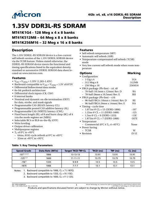
1.35V <strong>DDR3L</strong>-<strong>RS</strong> <strong>SDRAM</strong><br />
MT41K1G4 - 128 Meg x 4 x 8 banks<br />
MT41K512M8 – 64 Meg x 8 x 8 banks<br />
MT41K256M16 – 32 Meg x 16 x 8 banks<br />
Description<br />
The 1.35V <strong>DDR3L</strong>-<strong>RS</strong> <strong>SDRAM</strong> device is a low-current<br />
self refresh version of the 1.35V <strong>DDR3L</strong> <strong>SDRAM</strong> device<br />
via the TCSR feature. Unless stated otherwise, the<br />
<strong>DDR3L</strong>-<strong>RS</strong> <strong>SDRAM</strong> device meets the functional and<br />
timing specifications listed in the equivalent density<br />
standard or automotive <strong>DDR3L</strong> <strong>SDRAM</strong> data sheet located<br />
on www.micron.com.<br />
Features<br />
• V DD = V DDQ = 1.35V (1.283–1.45V)<br />
• Backward-compatible to V DD = V DDQ = 1.5V ±0.075V<br />
• Differential bidirectional data strobe<br />
• 8n-bit prefetch architecture<br />
• Differential clock inputs (CK, CK#)<br />
• 8 internal banks<br />
• Nominal and dynamic on-die termination (ODT)<br />
for data, strobe, and mask signals<br />
• Programmable CAS (READ) latency (CL)<br />
• Programmable posted CAS additive latency (AL)<br />
• Programmable CAS (WRITE) latency (CWL)<br />
• Fixed burst length (BL) of 8 and burst chop (BC) of 4<br />
(via the mode register set [M<strong>RS</strong>])<br />
• Selectable BC4 or BL8 on-the-fly (OTF)<br />
• Write leveling<br />
• Output driver calibration<br />
• Multipurpose register<br />
• T C of 0°C to +95°C<br />
– 64ms, 8192-cycle refresh at 0°C to +85°C<br />
– 32ms at +85°C to +95°C<br />
Table 1: Key Timing Parameters<br />
Features<br />
• Self refresh temperature (SRT)<br />
• Automatic self refresh (ASR)<br />
• Temperature-compensated self refresh (TCSR)<br />
mode<br />
• Very low current self refresh mode when room temperature<br />
Options Marking<br />
• Configuration<br />
– 1 Gig x 4 1G4<br />
– 512 Meg x 8 512M8<br />
– 256 Meg x 16 256M16<br />
• FBGA package (Pb-free) – <strong>x4</strong>, <strong>x8</strong><br />
– 78-ball (10.5mm x 12mm) Rev. D RA<br />
– 78-ball (9mm x 10.5mm) Rev. E RH<br />
• FBGA package (Pb-free) – <strong>x16</strong><br />
– 96-ball FBGA (10mm x 14mm) Rev. D RE<br />
– 96-ball FBGA (9mm x 14mm) Rev. E HA<br />
• Timing – cycle time<br />
– 1.071ns @ CL = 13 (DDR3-1866) -107<br />
– 1.25ns @ CL = 11 (DDR3-1600) -125<br />
– 1.5ns @ CL = 9 (DDR3-1333) -15E<br />
– 1.875ns @ CL = 7 (DDR3-1066) -187E<br />
• Temperature<br />
– Commercial (0°C ≤ T C ≤ +95°C) None<br />
• Power Saving<br />
– TCSR M<br />
• Revision :D/:E<br />
Speed Grade Data Rate (MT/s) Target t RCD- t RP-CL t RCD (ns) t RP (ns) CL (ns)<br />
-107 1, 2, 3 1866 13-13-13 13.91 13.91 13.91<br />
-125 1, 2 1600 11-11-11 13.75 13.75 13.75<br />
-15E 1 1333 9-9-9 13.5 13.5 13.5<br />
-187E 1066 7-7-7 13.1 13.1 13.1<br />
Notes: 1. Backward compatible to 1066, CL = 7 (-187E).<br />
2. Backward compatible to 1333, CL = 9 (-15E).<br />
3. Backward compatible to 1600, CL =11 (-125).<br />
<strong>4Gb</strong>: <strong>x4</strong>, <strong>x8</strong>, <strong>x16</strong> <strong>DDR3L</strong>-<strong>RS</strong> <strong>SDRAM</strong><br />
Description<br />
PDF: 09005aef8488935b<br />
<strong>4Gb</strong>_1_35V_<strong>DDR3L</strong>-<strong>RS</strong>.pdf - Rev. H 10/12 EN 1 <strong>Micron</strong> Technology, Inc. reserves the right to change products or specifications without notice.<br />
© 2011 <strong>Micron</strong> Technology, Inc. All rights reserved.<br />
Products and specifications discussed herein are subject to change by <strong>Micron</strong> without notice.
Table 2: Addressing<br />
Parameter 1 Gig x 4 512 Meg x 8 256 Meg x 16<br />
Configuration 128 Meg x 4 x 8 banks 64 Meg x 8 x 8 banks 32 Meg x 16 x 8 banks<br />
Refresh count 8K 8K 8K<br />
Row address 64K (A[15:0]) 64K (A[15:0]) 32K (A[14:0])<br />
Bank address 8 (BA[2:0]) 8 (BA[2:0]) 8 (BA[2:0])<br />
Column address 2K (A[11, 9:0]) 1K (A[9:0]) 1K (A[9:0])<br />
Page size 1KB 1KB 2KB<br />
Figure 1: <strong>DDR3L</strong>-<strong>RS</strong> Part Numbers<br />
Package<br />
Example Part Number: MT41K512M8RH-125M:E<br />
MT41K Configuration Package Speed PS Revision<br />
Configuration<br />
1 Gig x 4 1G4<br />
512 Meg x 8<br />
512M8<br />
256 Meg x 16 256M16<br />
78-ball 10.5mm x 12mm FBGA RA<br />
78-ball 9mm x 10.5mm FBGA<br />
96-ball 10mm x 14mm FBGA<br />
96-ball 9mm x 14mm FBGA<br />
RH<br />
RE<br />
HA<br />
-<br />
-107<br />
-125<br />
-15E<br />
-187E<br />
{<br />
Temperature<br />
Commercial<br />
:D/:E<br />
Speed Grade<br />
t<br />
CK = 1.071ns, CL = 13<br />
t<br />
CK = 1.25ns, CL = 11<br />
t<br />
CK = 1.5ns, CL = 9<br />
t CK = 1.87ns, CL = 7<br />
:<br />
Power Saving<br />
None<br />
Revision<br />
TCSR M<br />
Note: 1. Not all options listed can be combined to define an offered product. Use the part catalog search on<br />
http://www.micron.com for available offerings.<br />
FBGA Part Marking Decoder<br />
<strong>4Gb</strong>: <strong>x4</strong>, <strong>x8</strong>, <strong>x16</strong> <strong>DDR3L</strong>-<strong>RS</strong> <strong>SDRAM</strong><br />
Description<br />
Due to space limitations, FBGA-packaged components have an abbreviated part marking that is different from the<br />
part number. <strong>Micron</strong>’s FBGA part marking decoder is available at www.micron.com/decoder.<br />
PDF: 09005aef8488935b<br />
<strong>4Gb</strong>_1_35V_<strong>DDR3L</strong>-<strong>RS</strong>.pdf - Rev. H 10/12 EN 2 <strong>Micron</strong> Technology, Inc. reserves the right to change products or specifications without notice.<br />
© 2011 <strong>Micron</strong> Technology, Inc. All rights reserved.
Ball Assignments and Descriptions<br />
Figure 2: 78-Ball FBGA – <strong>x4</strong>, <strong>x8</strong> (Top View)<br />
A<br />
B<br />
C<br />
D<br />
E<br />
F<br />
G<br />
H<br />
J<br />
K<br />
L<br />
M<br />
N<br />
1 2 3 4 5 6 7 8 9<br />
V SS<br />
V SS<br />
V DDQ<br />
V SSQ<br />
V REFDQ<br />
NC<br />
ODT<br />
NC<br />
V SS<br />
V DD<br />
V SS<br />
V DD<br />
V SS<br />
V DD<br />
V SSQ<br />
DQ2<br />
NF, DQ6<br />
V DDQ<br />
V SS<br />
V DD<br />
CS#<br />
BA0<br />
A3<br />
A5<br />
A7<br />
RESET#<br />
NC<br />
DQ0<br />
DQS<br />
DQS#<br />
NF, DQ4<br />
RAS#<br />
CAS#<br />
WE#<br />
BA2<br />
A0<br />
A2<br />
A9<br />
A13<br />
<strong>4Gb</strong>: <strong>x4</strong>, <strong>x8</strong>, <strong>x16</strong> <strong>DDR3L</strong>-<strong>RS</strong> <strong>SDRAM</strong><br />
Ball Assignments and Descriptions<br />
NF, NF/TDQS#<br />
DM, DM/TDQS VSSQ DQ1<br />
V DD<br />
NF, DQ7 NF, DQ5<br />
CK<br />
CK#<br />
A10/AP<br />
A15<br />
A12/BC#<br />
Notes: 1. Ball descriptions listed in Table 3 (page 5) are listed as “<strong>x4</strong>, <strong>x8</strong>” if unique; otherwise,<br />
<strong>x4</strong> and <strong>x8</strong> are the same.<br />
2. A comma separates the configuration; a slash defines a selectable function.<br />
Example D7 = NF, NF/TDQS#. NF applies to the <strong>x4</strong> configuration only. NF/TDQS# applies<br />
to the <strong>x8</strong> configuration only—selectable between NF or TDQS# via M<strong>RS</strong> (symbols are defined<br />
in Table 3).<br />
PDF: 09005aef8488935b<br />
<strong>4Gb</strong>_1_35V_<strong>DDR3L</strong>-<strong>RS</strong>.pdf - Rev. H 10/12 EN 3 <strong>Micron</strong> Technology, Inc. reserves the right to change products or specifications without notice.<br />
© 2011 <strong>Micron</strong> Technology, Inc. All rights reserved.<br />
A1<br />
A11<br />
A14<br />
V SS<br />
DQ3<br />
V SS<br />
V SS<br />
V DD<br />
ZQ<br />
V REFCA<br />
BA1<br />
A4<br />
A6<br />
A8<br />
V DD<br />
V DDQ<br />
V SSQ<br />
V SSQ<br />
V DDQ<br />
NC<br />
CKE<br />
NC<br />
V SS<br />
V DD<br />
V SS<br />
V DD<br />
V SS
Figure 3: 96-Ball FBGA – <strong>x16</strong> (Top View)<br />
A<br />
B<br />
C<br />
D<br />
E<br />
F<br />
G<br />
H<br />
J<br />
K<br />
L<br />
M<br />
N<br />
P<br />
R<br />
T<br />
1 2 3 4 5 6 7 8 9<br />
V DDQ<br />
V SSQ<br />
V DDQ<br />
V SSQ<br />
V SS<br />
V DDQ<br />
V SSQ<br />
V REFDQ<br />
NC<br />
ODT<br />
NC<br />
V SS<br />
V DD<br />
V SS<br />
V DD<br />
V SS<br />
DQ13<br />
V DD<br />
DQ11<br />
V DDQ<br />
V SSQ<br />
DQ2<br />
DQ6<br />
V DDQ<br />
V SS<br />
V DD<br />
CS#<br />
BA0<br />
A3<br />
A5<br />
A7<br />
RESET#<br />
DQ15<br />
V SS<br />
DQ9<br />
UDM<br />
DQ0<br />
LDQS<br />
LDQS#<br />
DQ4<br />
RAS#<br />
CAS#<br />
WE#<br />
BA2<br />
A0<br />
A2<br />
A9<br />
A13<br />
Note: 1. A slash defines a selectable function.<br />
<strong>4Gb</strong>: <strong>x4</strong>, <strong>x8</strong>, <strong>x16</strong> <strong>DDR3L</strong>-<strong>RS</strong> <strong>SDRAM</strong><br />
Ball Assignments and Descriptions<br />
DQ12<br />
UDQS#<br />
UDQS<br />
DQ8<br />
LDM<br />
DQ1<br />
V DD<br />
DQ7<br />
CK<br />
CK#<br />
A10/AP<br />
NC<br />
A12/BC#<br />
PDF: 09005aef8488935b<br />
<strong>4Gb</strong>_1_35V_<strong>DDR3L</strong>-<strong>RS</strong>.pdf - Rev. H 10/12 EN 4 <strong>Micron</strong> Technology, Inc. reserves the right to change products or specifications without notice.<br />
© 2011 <strong>Micron</strong> Technology, Inc. All rights reserved.<br />
A1<br />
A11<br />
A14<br />
V DDQ<br />
DQ14<br />
DQ10<br />
V SSQ<br />
V SSQ<br />
DQ3<br />
V SS<br />
DQ5<br />
V SS<br />
V DD<br />
ZQ<br />
V REFCA<br />
BA1<br />
A4<br />
A6<br />
A8<br />
V SS<br />
V SSQ<br />
V DDQ<br />
V DD<br />
V DDQ<br />
V SSQ<br />
V SSQ<br />
V DDQ<br />
NC<br />
CKE<br />
NC<br />
V SS<br />
V DD<br />
V SS<br />
V DD<br />
V SS
Table 3: 78-Ball FBGA – <strong>x4</strong>, <strong>x8</strong> Ball Descriptions<br />
Symbol Type Description<br />
[15:13], A12/BC#,<br />
A11, A10/AP, A[9:0]<br />
<strong>4Gb</strong>: <strong>x4</strong>, <strong>x8</strong>, <strong>x16</strong> <strong>DDR3L</strong>-<strong>RS</strong> <strong>SDRAM</strong><br />
Ball Assignments and Descriptions<br />
Input Address inputs: Provide the row address for ACTIVATE commands, and the column<br />
address and auto precharge bit (A10) for READ/WRITE commands, to select one<br />
location out of the memory array in the respective bank. A10 sampled during a<br />
PRECHARGE command determines whether the PRECHARGE applies to one bank<br />
(A10 LOW, bank selected by BA[2:0]) or all banks (A10 HIGH). The address inputs also<br />
provide the op-code during a LOAD MODE command. Address inputs are referenced<br />
to V REFCA. A12/BC#: When enabled in the mode register (MR), A12 is sampled during<br />
READ and WRITE commands to determine whether burst chop (on-the-fly) will be<br />
performed (HIGH = BL8 or no burst chop, LOW = BC4). See Truth Table - Command in<br />
the DDR3 <strong>SDRAM</strong> data sheet.<br />
BA[2:0] Input Bank address inputs: BA[2:0] define the bank to which an ACTIVATE, READ,<br />
WRITE, or PRECHARGE command is being applied. BA[2:0] define which mode<br />
register (MR0, MR1, MR2, or MR3) is loaded during the LOAD MODE command.<br />
BA[2:0] are referenced to V REFCA.<br />
CK, CK# Input Clock: CK and CK# are differential clock inputs. All control and address input signals<br />
are sampled on the crossing of the positive edge of CK and the negative edge of<br />
CK#. Output data strobe (DQS, DQS#) is referenced to the crossings of CK and CK#.<br />
CKE Input Clock enable: CKE enables (registered HIGH) and disables (registered LOW)<br />
internal circuitry and clocks on the DRAM. The specific circuitry that is enabled/<br />
disabled is dependent upon the DDR3 <strong>SDRAM</strong> configuration and operating mode.<br />
Taking CKE LOW provides PRECHARGE POWER-DOWN and SELF REFRESH operations<br />
(all banks idle), or active power-down (row active in any bank). CKE is synchronous<br />
for power-down entry and exit and for self refresh entry. CKE is asynchronous for<br />
self refresh exit. Input buffers (excluding CK, CK#, CKE, RESET#, and ODT) are<br />
disabled during POWER-DOWN. Input buffers (excluding CKE and RESET#) are disabled<br />
during SELF REFRESH. CKE is referenced to V REFCA.<br />
CS# Input Chip select: CS# enables (registered LOW) and disables (registered HIGH) the<br />
command decoder. All commands are masked when CS# is registered HIGH. CS#<br />
provides for external rank selection on systems with multiple ranks. CS# is considered<br />
part of the command code. CS# is referenced to V REFCA.<br />
DM Input Input data mask: DM is an input mask signal for write data. Input data is masked<br />
when DM is sampled HIGH along with the input data during a write access.<br />
Although the DM ball is input-only, the DM loading is designed to match that of the<br />
DQ and DQS balls. DM is referenced to V REFDQ. DM has an optional use as TDQS on<br />
the <strong>x8</strong>.<br />
ODT Input On-die termination: ODT enables (registered HIGH) and disables (registered LOW)<br />
termination resistance internal to the DDR3 <strong>SDRAM</strong>. When enabled in normal<br />
operation, ODT is only applied to each of the following balls: DQ[7:0], DQS, DQS#,<br />
and DM for the <strong>x8</strong>; DQ[3:0], DQS, DQS#, and DM for the <strong>x4</strong>. The ODT input is<br />
ignored if disabled via the LOAD MODE command. ODT is referenced to REFCA.<br />
RAS#, CAS#, WE# Input Command inputs: RAS#, CAS#, and WE# (along with CS#) define the command<br />
being entered and are referenced to V REFCA.<br />
RESET# Input Reset: RESET# is an active LOW CMOS input referenced to V SS. The RESET# input receiver<br />
is a CMOS input defined as a rail-to-rail signal with DC HIGH ≥ 0.8 × V DD and<br />
DC LOW ≤ 0.2 × V DDQ. RESET# assertion and desertion are asynchronous.<br />
PDF: 09005aef8488935b<br />
<strong>4Gb</strong>_1_35V_<strong>DDR3L</strong>-<strong>RS</strong>.pdf - Rev. H 10/12 EN 5 <strong>Micron</strong> Technology, Inc. reserves the right to change products or specifications without notice.<br />
© 2011 <strong>Micron</strong> Technology, Inc. All rights reserved.
Table 3: 78-Ball FBGA – <strong>x4</strong>, <strong>x8</strong> Ball Descriptions (Continued)<br />
Symbol Type Description<br />
DQ[3:0] I/O Data input/output: Bidirectional data bus for the <strong>x4</strong> configuration. DQ[3:0] are<br />
referenced to REFDQ.<br />
DQ[7:0] I/O Data input/output: Bidirectional data bus for the <strong>x8</strong> configuration. DQ[7:0] are<br />
referenced to V REFDQ.<br />
DQS, DQS# I/O Data strobe: Output with read data. Edge-aligned with read data. Input with write<br />
data. Center-aligned to write data.<br />
TDQS, TDQS# Output Termination data strobe: Applies to the <strong>x8</strong> configuration only. When TDQS is<br />
enabled, DM is disabled, and the TDQS and TDQS# balls provide termination<br />
resistance.<br />
V DD Supply Power supply: 1.35V, 1.283–1.45V operational; compatible to 1.5V operation.<br />
V DDQ Supply DQ power supply: 1.35V, 1.283–1.45V operational; compatible to 1.5V operation.<br />
V REFCA Supply Reference voltage for control, command, and address: V REFCA must be<br />
maintained at all times (including self refresh) for proper device operation.<br />
V REFDQ Supply Reference voltage for data: REFDQ must be maintained at all times (excluding self<br />
refresh) for proper device operation.<br />
V SS Supply Ground.<br />
<strong>4Gb</strong>: <strong>x4</strong>, <strong>x8</strong>, <strong>x16</strong> <strong>DDR3L</strong>-<strong>RS</strong> <strong>SDRAM</strong><br />
Ball Assignments and Descriptions<br />
V SSQ Supply DQ ground: Isolated on the device for improved noise immunity.<br />
ZQ Reference External reference ball for output drive calibration: This ball is tied to an<br />
external 240Ω resistor (RZQ), which is tied to V SSQ.<br />
NC – No connect: These balls should be left unconnected (the ball has no connection to<br />
the DRAM or to other balls).<br />
NF – No function: When configured as a <strong>x4</strong> device, these balls are NF. When configured<br />
as a <strong>x8</strong> device, these balls are defined as TDQS#, DQ[7:4].<br />
PDF: 09005aef8488935b<br />
<strong>4Gb</strong>_1_35V_<strong>DDR3L</strong>-<strong>RS</strong>.pdf - Rev. H 10/12 EN 6 <strong>Micron</strong> Technology, Inc. reserves the right to change products or specifications without notice.<br />
© 2011 <strong>Micron</strong> Technology, Inc. All rights reserved.
Table 4: 96-Ball FBGA – <strong>x16</strong> Ball Descriptions<br />
Symbol Type Description<br />
[14:13], A12/BC#,<br />
A11, A10/AP, A[9:0]<br />
<strong>4Gb</strong>: <strong>x4</strong>, <strong>x8</strong>, <strong>x16</strong> <strong>DDR3L</strong>-<strong>RS</strong> <strong>SDRAM</strong><br />
Ball Assignments and Descriptions<br />
Input Address inputs: Provide the row address for ACTIVATE commands, and the column<br />
address and auto precharge bit (A10) for READ/WRITE commands, to select one<br />
location out of the memory array in the respective bank. A10 sampled during a<br />
PRECHARGE command determines whether the PRECHARGE applies to one bank<br />
(A10 LOW, bank selected by BA[2:0]) or all banks (A10 HIGH). The address inputs also<br />
provide the op-code during a LOAD MODE command. Address inputs are referenced<br />
to V REFCA. A12/BC#: When enabled in the mode register (MR), A12 is sampled during<br />
READ and WRITE commands to determine whether burst chop (on-the-fly) will be<br />
performed (HIGH = BL8 or no burst chop, LOW = BC4). See Truth Table - Command in<br />
the DDR3 <strong>SDRAM</strong> data sheet.<br />
BA[2:0] Input Bank address inputs: BA[2:0] define the bank to which an ACTIVATE, READ,<br />
WRITE, or PRECHARGE command is being applied. BA[2:0] define which mode<br />
register (MR0, MR1, MR2, or MR3) is loaded during the LOAD MODE command.<br />
BA[2:0] are referenced to V REFCA.<br />
CK, CK# Input Clock: CK and CK# are differential clock inputs. All control and address input signals<br />
are sampled on the crossing of the positive edge of CK and the negative edge of<br />
CK#. Output data strobe (DQS, DQS#) is referenced to the crossings of CK and CK#.<br />
CKE Input Clock enable: CKE enables (registered HIGH) and disables (registered LOW) internal<br />
circuitry and clocks on the DRAM. The specific circuitry that is enabled/disabled is dependent<br />
upon the DDR3 <strong>SDRAM</strong> configuration and operating mode. Taking CKE<br />
LOW provides PRECHARGE POWER-DOWN and SELF REFRESH operations (all banks<br />
idle),or active power-down (row active in any bank). CKE is synchronous for powerdown<br />
entry and exit and for self refresh entry. CKE is asynchronous for self refresh<br />
exit. Input buffers (excluding CK, CK#, CKE, RESET#, and ODT) are disabled during<br />
POWER-DOWN. Input buffers (excluding CKE and RESET#) are disabled during SELF<br />
REFRESH. CKE is referenced to V REFCA.<br />
CS# Input Chip select: CS# enables (registered LOW) and disables (registered HIGH) the<br />
command decoder. All commands are masked when CS# is registered HIGH. CS# provides<br />
for external rank selection on systems with multiple ranks. CS# is considered<br />
part of the command code. CS# is referenced to V REFCA.<br />
LDM Input Input data mask: LDM is a lower-byte, input mask signal for write data. Lower-byte<br />
input data is masked when LDM is sampled HIGH along with the input data during a<br />
write access. Although the LDM ball is input-only, the LDM loading is<br />
designed to match that of the DQ and DQS balls. LDM is referenced to V REFDQ.<br />
ODT Input On-die termination: ODT enables (registered HIGH) and disables (registered LOW)<br />
termination resistance internal to the DDR3 <strong>SDRAM</strong>. When enabled in normal<br />
operation, ODT is only applied to each of the following balls: DQ[15:0], LDQS,<br />
LDQS#, UDQS, UDQS#, LDM, and UDM for the <strong>x16</strong>; DQ0[7:0], DQS, DQS#, DM/TDQS,<br />
and NF/TDQS# (when TDQS is enabled) for the <strong>x8</strong>; DQ[3:0], DQS, DQS#, and DM for<br />
the <strong>x4</strong>. The ODT input is ignored if disabled via the LOAD MODE command. ODT is<br />
referenced to V REFCA.<br />
RAS#, CAS#, WE# Input Command inputs: RAS#, CAS#, and WE# (along with CS#) define the command<br />
being entered and are referenced to V REFCA.<br />
PDF: 09005aef8488935b<br />
<strong>4Gb</strong>_1_35V_<strong>DDR3L</strong>-<strong>RS</strong>.pdf - Rev. H 10/12 EN 7 <strong>Micron</strong> Technology, Inc. reserves the right to change products or specifications without notice.<br />
© 2011 <strong>Micron</strong> Technology, Inc. All rights reserved.
Table 4: 96-Ball FBGA – <strong>x16</strong> Ball Descriptions (Continued)<br />
Symbol Type Description<br />
RESET# Input Reset: RESET# is an active LOW CMOS input referenced to V SS. The RESET# input receiver<br />
is a CMOS input defined as a rail-to-rail signal with DC HIGH ≥ 0.8 × V DD and<br />
DC LOW ≤ 0.2 × V DDQ. RESET# assertion and desertion are asynchronous.<br />
UDM Input Input data mask: UDM is an upper-byte, input mask signal for write data. Upperbyte<br />
input data is masked when UDM is sampled HIGH along with that input data<br />
during a WRITE access. Although the UDM ball is input-only, the UDM loading is<br />
designed to match that of the DQ and DQS balls. UDM is referenced to V REFDQ.<br />
DQ[7:0] I/O Data input/output: Lower byte of bidirectional data bus for the <strong>x16</strong> configuration.<br />
DQ[7:0] are referenced to V REFDQ.<br />
DQ[15:8] I/O Data input/output: Upper byte of bidirectional data bus for the <strong>x16</strong> configuration.<br />
DQ[15:8] are referenced to V REFDQ.<br />
LDQS, LDQS# I/O Lower byte data strobe: Output with read data. Edge-aligned with read data.<br />
Input with write data. Center-aligned to write data.<br />
UDQS, UDQS# I/O Upper byte data strobe: Output with read data. Edge-aligned with read data.<br />
Input with write data. DQS is center-aligned to write data.<br />
V DD Supply Power supply: 1.35V, 1.283–1.45V operational; compatible to 1.5V operation.<br />
V DDQ Supply DQ power supply: 1.35V, 1.283–1.45V operational; compatible to 1.5V operation.<br />
V REFCA Supply Reference voltage for control, command, and address: V REFCA must be<br />
maintained at all times (including self refresh) for proper device operation.<br />
V REFDQ Supply Reference voltage for data: V REFDQ must be maintained at all times (excluding self<br />
refresh) for proper device operation.<br />
V SS Supply Ground.<br />
<strong>4Gb</strong>: <strong>x4</strong>, <strong>x8</strong>, <strong>x16</strong> <strong>DDR3L</strong>-<strong>RS</strong> <strong>SDRAM</strong><br />
Ball Assignments and Descriptions<br />
V SSQ Supply DQ ground: Isolated on the device for improved noise immunity.<br />
ZQ Reference External reference ball for output drive calibration: This ball is tied to an<br />
external 240Ω resistor (RZQ), which is tied to V SSQ.<br />
NC – No connect: These balls should be left unconnected (the ball has no connection to<br />
the DRAM or to other balls).<br />
PDF: 09005aef8488935b<br />
<strong>4Gb</strong>_1_35V_<strong>DDR3L</strong>-<strong>RS</strong>.pdf - Rev. H 10/12 EN 8 <strong>Micron</strong> Technology, Inc. reserves the right to change products or specifications without notice.<br />
© 2011 <strong>Micron</strong> Technology, Inc. All rights reserved.
Package Dimensions<br />
Figure 4: 78-Ball FBGA – <strong>x4</strong>, <strong>x8</strong> (RA)<br />
12 ±0.1<br />
0.155<br />
78X Ø0.45<br />
Dimensions apply<br />
to solder balls postreflow<br />
on Ø0.35 SMD<br />
ball pads.<br />
9.6 CTR<br />
0.8 TYP<br />
9<br />
1.8 CTR<br />
Nonconductive<br />
overmold<br />
8<br />
7<br />
0.8 TYP<br />
6.4 CTR<br />
10.5 ±0.1<br />
3<br />
2<br />
1<br />
A<br />
B<br />
C<br />
D<br />
E<br />
F<br />
G<br />
H<br />
J<br />
K<br />
L<br />
M<br />
N<br />
Note: 1. All dimensions are in millimeters.<br />
A<br />
<strong>4Gb</strong>: <strong>x4</strong>, <strong>x8</strong>, <strong>x16</strong> <strong>DDR3L</strong>-<strong>RS</strong> <strong>SDRAM</strong><br />
Package Dimensions<br />
Seating plane<br />
0.12 A<br />
Ball A1 ID Ball A1 ID<br />
1.1 ±0.1<br />
0.25 MIN<br />
PDF: 09005aef8488935b<br />
<strong>4Gb</strong>_1_35V_<strong>DDR3L</strong>-<strong>RS</strong>.pdf - Rev. H 10/12 EN 9 <strong>Micron</strong> Technology, Inc. reserves the right to change products or specifications without notice.<br />
© 2011 <strong>Micron</strong> Technology, Inc. All rights reserved.
Figure 5: 78-Ball FBGA – <strong>x4</strong>, <strong>x8</strong> (RH)<br />
10.5 ±0.1<br />
9.6 CTR<br />
0.8 TYP<br />
0.155<br />
78X Ø0.45<br />
Dimensions apply<br />
to solder balls postreflow<br />
on Ø0.35 SMD<br />
ball pads.<br />
9<br />
8<br />
1.8 CTR<br />
Nonconductive<br />
overmold<br />
7<br />
0.8 TYP<br />
6.4 CTR<br />
9 ±0.1<br />
3<br />
2<br />
Note: 1. All dimensions are in millimeters.<br />
1<br />
A<br />
B<br />
C<br />
D<br />
E<br />
F<br />
G<br />
H<br />
J<br />
K<br />
L<br />
M<br />
N<br />
A<br />
Seating plane<br />
0.12 A<br />
Ball A1 ID<br />
(covered by SR)<br />
<strong>4Gb</strong>: <strong>x4</strong>, <strong>x8</strong>, <strong>x16</strong> <strong>DDR3L</strong>-<strong>RS</strong> <strong>SDRAM</strong><br />
Package Dimensions<br />
0.25 MIN<br />
1.1 ±0.1<br />
Ball A1 ID<br />
PDF: 09005aef8488935b<br />
<strong>4Gb</strong>_1_35V_<strong>DDR3L</strong>-<strong>RS</strong>.pdf - Rev. H 10/12 EN 10 <strong>Micron</strong> Technology, Inc. reserves the right to change products or specifications without notice.<br />
© 2011 <strong>Micron</strong> Technology, Inc. All rights reserved.
Figure 6: 96-Ball FBGA – <strong>x16</strong> (RE)<br />
14 ±0.1<br />
0.155<br />
96X Ø0.45<br />
Dimensions apply<br />
to solder balls<br />
post-reflow on<br />
Ø0.35 SMD ball pads<br />
12 CTR<br />
0.8 TYP<br />
9<br />
1.8 CTR<br />
Nonconductive<br />
overmold<br />
8<br />
7<br />
0.8 TYP<br />
6.4 CTR<br />
10 ±0.1<br />
3<br />
2<br />
1<br />
A<br />
B<br />
C<br />
D<br />
E<br />
F<br />
G<br />
H<br />
J<br />
K<br />
L<br />
M<br />
N<br />
P<br />
R<br />
T<br />
Note: 1. All dimensions are in millimeters.<br />
A<br />
<strong>4Gb</strong>: <strong>x4</strong>, <strong>x8</strong>, <strong>x16</strong> <strong>DDR3L</strong>-<strong>RS</strong> <strong>SDRAM</strong><br />
Package Dimensions<br />
Seating plane<br />
0.12 A<br />
Ball A1 ID Ball A1 ID<br />
1.1 ±0.1<br />
0.25 MIN<br />
PDF: 09005aef8488935b<br />
<strong>4Gb</strong>_1_35V_<strong>DDR3L</strong>-<strong>RS</strong>.pdf - Rev. H 10/12 EN 11 <strong>Micron</strong> Technology, Inc. reserves the right to change products or specifications without notice.<br />
© 2011 <strong>Micron</strong> Technology, Inc. All rights reserved.
Figure 7: 96-Ball FBGA – <strong>x16</strong> (HA)<br />
96X Ø0.45<br />
Dimensions<br />
apply to solder<br />
balls post-reflow<br />
on Ø0.35 SMD<br />
ball pads.<br />
12 CTR<br />
0.155<br />
0.8 TYP<br />
1.8 CTR<br />
Nonconductive<br />
overmold<br />
9 8 7 3 2 1<br />
0.8 TYP<br />
6.4 CTR<br />
9 ±0.1<br />
A 0.12 A<br />
A<br />
B<br />
C<br />
D<br />
E<br />
F<br />
G<br />
H<br />
J<br />
K<br />
L<br />
M<br />
N<br />
P<br />
R<br />
T<br />
Ball A1 Index<br />
(covered by SR)<br />
14 ±0.1<br />
Note: 1. All dimensions are in millimeters.<br />
<strong>4Gb</strong>: <strong>x4</strong>, <strong>x8</strong>, <strong>x16</strong> <strong>DDR3L</strong>-<strong>RS</strong> <strong>SDRAM</strong><br />
Package Dimensions<br />
Seating plane<br />
1.1 ±0.1<br />
0.25 MIN<br />
Ball A1 Index<br />
PDF: 09005aef8488935b<br />
<strong>4Gb</strong>_1_35V_<strong>DDR3L</strong>-<strong>RS</strong>.pdf - Rev. H 10/12 EN 12 <strong>Micron</strong> Technology, Inc. reserves the right to change products or specifications without notice.<br />
© 2011 <strong>Micron</strong> Technology, Inc. All rights reserved.
Electrical Characteristics – I DD Specifications<br />
Table 5: I DD Maximum Limits – Die Rev. D<br />
Speed Bin <strong>DDR3L</strong>-<strong>RS</strong><br />
Parameter Symbol Width -1066<br />
Operating current 0: One bank<br />
ACTIVATE-to-PRECHARGE<br />
Operating current 1: One bank<br />
ACTIVATE-to-READ-to-PRECHARGE<br />
Precharge power-down current:<br />
Slow exit<br />
Precharge power-down current:<br />
Fast exit<br />
<strong>4Gb</strong>: <strong>x4</strong>, <strong>x8</strong>, <strong>x16</strong> <strong>DDR3L</strong>-<strong>RS</strong> <strong>SDRAM</strong><br />
Electrical Characteristics – I DD Specifications<br />
<strong>DDR3L</strong>-<strong>RS</strong><br />
-1333<br />
<strong>DDR3L</strong>-<strong>RS</strong><br />
-1600 Unit Notes<br />
I DD0 <strong>x4</strong>,<strong>x8</strong> 60 65 75 mA 1<br />
<strong>x16</strong> 75 80 90 mA 1<br />
I DD1 <strong>x4</strong> 70 75 80 mA 1<br />
<strong>x8</strong> 77 82 87 mA 1<br />
<strong>x16</strong> 105 110 115 mA 1<br />
I DD2P0 All 15 15 15 mA 1<br />
I DD2P1 All 28 30 35 mA 1<br />
Precharge quiet standby current I DD2Q All 39 42 47 mA 1<br />
Precharge standby current I DD2N All 39 42 47 mA 1<br />
Precharge standby ODT current I DD2NT <strong>x4</strong>, <strong>x8</strong> 40 45 50 mA 1<br />
<strong>x16</strong> 45 50 55 mA 1<br />
Active power-down current I DD3P All 45 50 55 mA 1<br />
Active standby current I DD3N <strong>x4</strong>, <strong>x8</strong> 47 52 57 mA 1<br />
<strong>x16</strong> 60 65 70 mA 1<br />
Burst read operating current I DD4R <strong>x4</strong> 125 145 165 mA 1<br />
<strong>x8</strong> 137 157 177 mA 1<br />
<strong>x16</strong> 210 230 270 mA 1<br />
Burst write operating current I DD4W <strong>x4</strong> 105 125 145 mA 1<br />
<strong>x8</strong> 115 135 155 mA 1<br />
<strong>x16</strong> 170 190 215 mA 1<br />
Burst refresh current I DD5B All 200 205 215 mA 1<br />
Room temperature self refresh I DD6 All 5.8 5.8 5.8 mA 2<br />
+45°C temperature self refresh I DD6 All 6.0 6.0 6.0 mA 3<br />
Elevated temperature self refresh I DD6 All 10 10 10 mA 4<br />
All 12 12 12 mA 5<br />
Extended temperature self refresh I DD6ET All 16 16 16 mA 6<br />
All 22 22 22 mA 7<br />
All banks interleaved read current I DD7 <strong>x4</strong>,<strong>x8</strong> 200 240 280 mA 1<br />
<strong>x16</strong> 255 280 315 mA 1<br />
Reset current I DD8 all I DD2P0 + 2mA I DD2P0 + 2mA I DD2P0 + 2mA mA 1<br />
Notes: 1. T C = +85°C; SRT is disabled, ASR is disabled. Value is maximum.<br />
2. T C ≤ Room Temperature; SRT is disabled, ASR is enabled. Value is typical.<br />
3. T C ≤ +45°C; SRT is disabled, ASR is enabled. Value is typical.<br />
4. T C = +80°C; SRT is disabled, ASR is enabled. Value is typical.<br />
5. +45°C < T C ≤ +80°C; SRT is disabled, ASR is enabled. Value is maximum.<br />
PDF: 09005aef8488935b<br />
<strong>4Gb</strong>_1_35V_<strong>DDR3L</strong>-<strong>RS</strong>.pdf - Rev. H 10/12 EN 13 <strong>Micron</strong> Technology, Inc. reserves the right to change products or specifications without notice.<br />
© 2011 <strong>Micron</strong> Technology, Inc. All rights reserved.
<strong>4Gb</strong>: <strong>x4</strong>, <strong>x8</strong>, <strong>x16</strong> <strong>DDR3L</strong>-<strong>RS</strong> <strong>SDRAM</strong><br />
Electrical Characteristics – I DD Specifications<br />
6. T C = +95°C; SRT is disabled, ASR is enabled. Value is typical.<br />
7. +85°C < T C ≤ +95°C; SRT is disabled, ASR is enabled. Value is maximum.<br />
PDF: 09005aef8488935b<br />
<strong>4Gb</strong>_1_35V_<strong>DDR3L</strong>-<strong>RS</strong>.pdf - Rev. H 10/12 EN 14 <strong>Micron</strong> Technology, Inc. reserves the right to change products or specifications without notice.<br />
© 2011 <strong>Micron</strong> Technology, Inc. All rights reserved.
Table 6: I DD Maximum Limits – Die Rev. E<br />
Speed Bin <strong>DDR3L</strong>-<strong>RS</strong><br />
Parameter Symbol Width -1066<br />
Operating current 0: One bank<br />
ACTIVATE-to-PRECHARGE<br />
Operating current 1: One bank<br />
ACTIVATE-to-READ-to-PRE-<br />
CHARGE<br />
Precharge power-down current:<br />
Slow exit<br />
Precharge power-down current:<br />
Fast exit<br />
<strong>DDR3L</strong>-<strong>RS</strong><br />
-1333<br />
<strong>DDR3L</strong>-<strong>RS</strong><br />
-1600<br />
<strong>DDR3L</strong>-<strong>RS</strong><br />
-1866 Unit Notes<br />
I DD0 <strong>x4</strong>,<strong>x8</strong> 44 47 55 58 mA 1<br />
<strong>x16</strong> 55 58 66 69 mA 1<br />
I DD1 <strong>x4</strong> 53 57 61 65 mA 1<br />
<strong>x8</strong> 59 62 66 70 mA 1<br />
<strong>x16</strong> 80 84 87 91 mA 1<br />
I DD2P0 All 12 12 12 12 mA 1<br />
I DD2P1 All 24 26 30 35 mA 1<br />
Precharge quiet standby current I DD2Q All 22 24 27 30 mA 1<br />
Precharge standby current I DD2N All 22 24 26 29 mA 1<br />
Precharge standby ODT current I DD2NT <strong>x4</strong>, <strong>x8</strong> 27 30 34 37 mA 1<br />
<strong>x16</strong> 30 34 37 40 mA 1<br />
Active power-down current I DD3P All 27 30 33 36 mA 1<br />
Active standby current I DD3N <strong>x4</strong>, <strong>x8</strong> 29 32 35 38 mA 1<br />
<strong>x16</strong> 37 40 43 46 mA 1<br />
Burst read operating current I DD4R <strong>x4</strong> 105 122 139 160 mA 1<br />
<strong>x8</strong> 115 132 149 170 mA 1<br />
<strong>x16</strong> 176 193 227 244 mA 1<br />
Burst write operating current I DD4W <strong>x4</strong> 80 95 110 125 mA 1<br />
<strong>x8</strong> 87 103 118 133 mA 1<br />
<strong>x16</strong> 129 144 163 186 mA 1<br />
Burst refresh current I DD5B All 141 144 151 158 mA 1<br />
Room temperature self refresh I DD6 All 3.5 3.5 3.5 3.5 mA 2<br />
+45°C temperature self refresh I DD6A All 3.7 3.7 3.7 3.7 mA 3<br />
Elevated temperature self refresh<br />
Extended temperature self refresh<br />
All banks interleaved read current<br />
<strong>4Gb</strong>: <strong>x4</strong>, <strong>x8</strong>, <strong>x16</strong> <strong>DDR3L</strong>-<strong>RS</strong> <strong>SDRAM</strong><br />
Electrical Characteristics – I DD Specifications<br />
I DD6 All 7 7 7 7 mA 4<br />
All 8.5 8.5 8.5 8.5 mA 5<br />
I DD6ET All 14 14 14 14 mA 6<br />
All 18 18 18 18 mA 7<br />
I DD7 <strong>x8</strong> 152 182 213 243 mA 1<br />
<strong>x16</strong> 194 213 239 266 mA 1<br />
Reset current I DD8 all I DD2P0 + 2mA I DD2P0 + 2mA I DD2P0 + 2mA I DD2P0 + 2mA mA 1<br />
Notes: 1. T C = +85°C; SRT is disabled, ASR is disable. Value is maximum.<br />
2. Room Temperature; SRT is disabled, ASR is enabled. Value is typical.<br />
3. T C ≤ +45°C; SRT is disabled, ASR is enabled). Value is typical.<br />
4. T C = +80°C; SRT is disabled, ASR is enabled). Value is typical.<br />
5. +45°C < T C ≤ +80°C; SRT is disabled, ASR is enabled. Value is maximum.<br />
6. T C = +95°C; SRT is disabled, ASR is enabled. Value is typical.<br />
PDF: 09005aef8488935b<br />
<strong>4Gb</strong>_1_35V_<strong>DDR3L</strong>-<strong>RS</strong>.pdf - Rev. H 10/12 EN 15 <strong>Micron</strong> Technology, Inc. reserves the right to change products or specifications without notice.<br />
© 2011 <strong>Micron</strong> Technology, Inc. All rights reserved.
7. +85°C < T C ≤ +95°C; SRT is disabled, ASR is enabled. Value is maximum.<br />
Temperature Compensated Self Refresh (TCSR)<br />
Mode Register 2 (M<strong>RS</strong>)<br />
Figure 8: Mode Register 2 (MR2) Definition<br />
Temperature compensated self refresh (TCSR) feature substantially reduces the self refresh<br />
current (I DD6). TCSR takes affect when when T C is less than 45°C and the auto self<br />
refresh (ASR) function is enabled. ASR is required to utilize the TCSR feature and is enabled<br />
manually via Mode Register 2 (MR2[6]). See Figure 8 (page 16).<br />
Enabling ASR also automatically changes the DRAM self refresh rate from 1x to 2x when<br />
the case temperature exceeds +85°C. This allows the user to operate the DRAM beyond<br />
the standard 85°C limit up to the optional extended temperature range of +95°C while in<br />
self refresh mode.<br />
When ASR is disabled and T C is 0°C to 85°C, the self refresh mode’s refresh rate is assumed<br />
to be at the normal rate (sometimes referred to as 1x refresh rate). Also, if ASR is<br />
disabled and T C is 85°C to 95°C, the user must select the SRT extended temperature self<br />
refresh rate (sometimes referred to as 2x refresh rate). SRT is selected via mode register 2<br />
(MR2[7]) register. See Figure 8 (page 16).<br />
SPD settings should always support 05h (101 binary) in Byte 31.<br />
The mode register 2 (MR2) controls additional functions and features not available in<br />
the other mode registers. The auto self refresh (ASR) function is of particular interest for<br />
the <strong>DDR3L</strong>-<strong>RS</strong> <strong>SDRAM</strong> because the <strong>Micron</strong> <strong>DDR3L</strong>-<strong>RS</strong> <strong>SDRAM</strong> goes into TCSR mode<br />
when ASR has been enabled. This function is controlled via the bits shown in the figure<br />
below.<br />
M15 M14<br />
0<br />
0<br />
1<br />
1<br />
0<br />
1<br />
0<br />
1<br />
Mode Register<br />
Mode register set 0 (MR0)<br />
Mode register set 1 (MR1)<br />
Mode register set 2 (MR2)<br />
Mode register set 3 (MR3)<br />
M10 M9<br />
0<br />
0<br />
1<br />
1<br />
0<br />
1<br />
0<br />
1<br />
BA2 BA1 BA0 A13 A12 A11 A10 A9 A8 A7 A6 A5 A4 A3 A2 A1 A0<br />
16<br />
0 1<br />
Dynamic ODT<br />
(R TT(WR) )<br />
R TT(WR) disabled<br />
RZQ/4<br />
RZQ/2<br />
Reserved<br />
<strong>4Gb</strong>: <strong>x4</strong>, <strong>x8</strong>, <strong>x16</strong> <strong>DDR3L</strong>-<strong>RS</strong> <strong>SDRAM</strong><br />
Temperature Compensated Self Refresh (TCSR)<br />
15 14 13 12 11 10 9 8 7 6 5 4 3 2 1 0<br />
1 0 CWL<br />
1 0 0 ASR<br />
1 01 01 01 01 01 RTT(WR) SRT<br />
M7 Self Refresh Temperature<br />
0<br />
1<br />
Normal (0°C to 85°C)<br />
Extended (0°C to 95°C)<br />
M6<br />
0<br />
1<br />
Auto Self Refresh<br />
(Optional)<br />
Disabled: Manual<br />
Enabled: Automatic<br />
M5 M4 M3<br />
0<br />
0<br />
0<br />
0<br />
1<br />
1<br />
1<br />
1<br />
0<br />
0<br />
1<br />
1<br />
0<br />
0<br />
1<br />
1<br />
0<br />
1<br />
0<br />
1<br />
0<br />
1<br />
0<br />
1<br />
Address bus<br />
CAS Write Latency (CWL)<br />
5 CK ( t CK ≥ 2.5ns)<br />
6 CK (2.5ns > t CK ≥ 1.875ns)<br />
7 CK (1.875ns > t CK ≥ 1.5ns)<br />
8 CK (1.5ns > t CK ≥ 1.25ns)<br />
9 CK (1.25ns > t CK ≥ 1.07ns)<br />
Mode register 2 (MR2)<br />
10 CK (1.071ns > t CK ≥ 0.938ns)<br />
Reserved<br />
Reserved<br />
Note: 1. MR2[17, 14:11, 8, and 2:0] are reserved for future use and must all be programmed to 0.<br />
PDF: 09005aef8488935b<br />
<strong>4Gb</strong>_1_35V_<strong>DDR3L</strong>-<strong>RS</strong>.pdf - Rev. H 10/12 EN 16 <strong>Micron</strong> Technology, Inc. reserves the right to change products or specifications without notice.<br />
© 2011 <strong>Micron</strong> Technology, Inc. All rights reserved.
Electrical Specifications<br />
Table 7: Input/Output Capacitance<br />
Gray-shaded cells have the same values as those in the 1.5V DDR3 data sheet<br />
Capacitance<br />
Parameters Symbol<br />
<strong>DDR3L</strong>-800 <strong>DDR3L</strong>-1066 <strong>DDR3L</strong>-1333 <strong>DDR3L</strong>-1600 <strong>DDR3L</strong>-1866<br />
Min Max Min Max Min Max Min Max Min Max<br />
Single-end I/O: DQ, DM C IO 1.5 2.5 1.5 2.5 1.5 2.3 1.5 2.2 1.5 2.1 pF<br />
Differential I/O: DQS,<br />
DQS#, TDQS, TDQS#<br />
Inputs (CTRL,<br />
CMD,ADDR)<br />
<strong>4Gb</strong>: <strong>x4</strong>, <strong>x8</strong>, <strong>x16</strong> <strong>DDR3L</strong>-<strong>RS</strong> <strong>SDRAM</strong><br />
Electrical Specifications<br />
C IO 1.5 2.5 1.5 2.5 1.5 2.3 1.5 2.2 1.5 2.1 pF<br />
C I 0.75 1.3 0.75 1.3 0.75 1.3 0.75 1.2 0.75 1.2 pF<br />
Table 8: DC Electrical Characteristics and Operating Conditions – 1.35V Operation<br />
All voltages are referenced to V SS<br />
Parameter/Condition Symbol Min Nom Max Units Notes<br />
Supply voltage V DD 1.283 1.35 1.45 V 1, 2, 3, 4<br />
I/O supply voltage V DDQ 1.283 1.35 1.45 V 1, 2, 3, 4<br />
Units<br />
Notes: 1. Maximum DC value may not be greater than 1.425V. The DC value is the linear average<br />
of V DD/V DDQ(t) over a very long period of time (for example, 1 sec).<br />
2. If the maximum limit is exceeded, input levels shall be governed by DDR3 specifications.<br />
3. Under these supply voltages, the device operates to this <strong>DDR3L</strong> specification.<br />
4. Once initialized for <strong>DDR3L</strong> operation, DDR3 operation may only be used if the device is<br />
in reset while V DD and V DDQ are changed for DDR3 operation (see Figure 9 (page 29)).<br />
Table 9: DC Electrical Characteristics and Operating Conditions – 1.5V Operation<br />
All voltages are referenced to V SS<br />
Parameter/Condition Symbol Min Nom Max Units Notes<br />
Supply voltage V DD 1.425 1.5 1.575 V 1, 2, 3<br />
I/O supply voltage V DDQ 1.425 1.5 1.575 V 1, 2, 3<br />
Notes: 1. If the minimum limit is exceeded, input levels shall be governed by <strong>DDR3L</strong> specifications.<br />
2. Under 1.5V operation, this <strong>DDR3L</strong> device operates in accordance with the DDR3 specifications<br />
under the same speed timings as defined for this device.<br />
3. Once initialized for DDR3 operation, <strong>DDR3L</strong> operation may only be used if the device is<br />
in reset while V DD and V DDQ are changed for <strong>DDR3L</strong> operation (see Figure 9 (page 29)).<br />
PDF: 09005aef8488935b<br />
<strong>4Gb</strong>_1_35V_<strong>DDR3L</strong>-<strong>RS</strong>.pdf - Rev. H 10/12 EN 17 <strong>Micron</strong> Technology, Inc. reserves the right to change products or specifications without notice.<br />
© 2011 <strong>Micron</strong> Technology, Inc. All rights reserved.
Table 10: Input Switching Conditions – Command and Address<br />
Parameter/Condition Symbol <strong>DDR3L</strong>-800/1066 <strong>DDR3L</strong>-1333/1600 <strong>DDR3L</strong>-1866 Units<br />
Input high AC voltage: Logic 1 V IH(AC160)min 1 160 160 – mV<br />
Input high AC voltage: Logic 1 V IH(AC135)min 1 135 135 135 mV<br />
Input high AC voltage: Logic 1 V IH(AC125)min 1 – – 125 mV<br />
Input high DC voltage: Logic 1 V IH(DC90)min 90 90 90 mV<br />
Input low DC voltage: Logic 0 V IL(DC90)min –90 –90 –90 mV<br />
Input low AC voltage: Logic 0 V IL(AC125)min 1 – – –125 mV<br />
Input low AC voltage: Logic 0 V IL(AC135)min 1 –135 –135 –135 mV<br />
Input low AC voltage: Logic 0 V IL(AC160)min 1 –160 –160 – mV<br />
Note: 1. When two V IH(AC) values (and two corresponding V IL(AC) values) are listed for a specific<br />
speed bin, the user may choose either value for the input AC level. Whichever value is<br />
used, the associated setup time for that AC level must also be used. Additionally, one<br />
V IH(AC) value may be used for address/command inputs and the other V IH(AC) value may<br />
be used for data inputs.<br />
Table 11: Input Switching Conditions – DQ and DM<br />
<strong>4Gb</strong>: <strong>x4</strong>, <strong>x8</strong>, <strong>x16</strong> <strong>DDR3L</strong>-<strong>RS</strong> <strong>SDRAM</strong><br />
Electrical Specifications<br />
For example, for <strong>DDR3L</strong>-800, two input AC levels are defined: V IH(AC160),min and<br />
V IH(AC135),min (corresponding V IL(AC160),min and V IL(AC135),min). For DDRL-800, the address/<br />
command inputs must use either V IH(AC160),min with t IS(AC160) of 215ps or V IH(AC135),min<br />
with t IS(AC135) of 365ps; independently, the data inputs may use either V IH(AC160),min or<br />
V IH(AC135),min.<br />
Parameter/Condition Symbol <strong>DDR3L</strong>-800/1066 <strong>DDR3L</strong>-1333/1600 <strong>DDR3L</strong>-1866 Units<br />
Input high AC voltage: Logic 1 V IH(AC160)min 1 160 160 – mV<br />
Input high AC voltage: Logic 1 V IH(AC135)min 1 135 135 135 mV<br />
Input high AC voltage: Logic 1 V IH(AC130)min 1 – – 130 mV<br />
Input high DC voltage: Logic 1 V IH(DC90)min 90 90 90 mV<br />
Input low DC voltage: Logic 0 V IL(DC90)min –90 –90 –90 mV<br />
Input low AC voltage: Logic 0 V IL(AC130)min 1 – – –130 mV<br />
Input low AC voltage: Logic 0 V IL(AC135)min 1 –135 –135 –135 mV<br />
Input low AC voltage: Logic 0 V IL(AC160)min 1 –160 –160 – mV<br />
Note: 1. When two V IH(AC) values (and two corresponding V IL(AC) values) are listed for a specific<br />
speed bin, the user may choose either value for the input AC level. Whichever value is<br />
used, the associated setup time for that AC level must also be used. Additionally, one<br />
V IH(AC) value may be used for address/command inputs and the other V IH(AC) value may<br />
be used for data inputs.<br />
For example, for <strong>DDR3L</strong>-800, two input AC levels are defined: V IH(AC160),min and<br />
V IH(AC135),min (corresponding V IL(AC160),min and V IL(AC135),min). For DDRL-800, the data inputs<br />
must use either V IH(AC160),min with t IS(AC160) of 90ps or V IH(AC135),min with t IS(AC135)<br />
of 140ps; independently, the address/command inputs may use either V IH(AC160),min or<br />
V IH(AC135),min.<br />
PDF: 09005aef8488935b<br />
<strong>4Gb</strong>_1_35V_<strong>DDR3L</strong>-<strong>RS</strong>.pdf - Rev. H 10/12 EN 18 <strong>Micron</strong> Technology, Inc. reserves the right to change products or specifications without notice.<br />
© 2011 <strong>Micron</strong> Technology, Inc. All rights reserved.
Table 12: Differential Input Operating Conditions (CK, CK# and DQS, DQS#)<br />
Parameter/Condition Symbol Min Max Units<br />
Differential input logic high – slew V IH,diff(AC)slew 180 N/A mV<br />
Differential input logic low – slew V IL,diff(AC)slew N/A –180 mV<br />
Differential input logic high V IH,diff(AC) 2 × (V IH(AC) - V REF) V DD/V DDQ mV<br />
Differential input logic low V IL,diff(AC) V SS/V SSQ 2 × (V IL(AC) - V REF) mV<br />
Single-ended high level for strobes V SEH V DDQ/2 + 160 V DDQ mV<br />
Single-ended high level for CK, CK# V DD/2 + 160 V DD mV<br />
Single-ended low level for strobes V SEL V SSQ V DDQ/2 - 160 mV<br />
Single-ended low level for CK, CK# V SS V DD/2 - 160 mV<br />
Table 13: Minimum Required Time t DVAC for CK/CK#, DQS/DQS# Differential for AC Ringback<br />
Slew Rate (V/ns)<br />
<strong>DDR3L</strong>-800/1066/1333/1600 <strong>DDR3L</strong>-1866<br />
t DVAC at<br />
320mV (ps)<br />
t DVAC at<br />
270mV (ps)<br />
<strong>4Gb</strong>: <strong>x4</strong>, <strong>x8</strong>, <strong>x16</strong> <strong>DDR3L</strong>-<strong>RS</strong> <strong>SDRAM</strong><br />
Electrical Specifications<br />
t DVAC at<br />
270mV (ps)<br />
t DVAC at<br />
250mV (ps)<br />
t DVAC at<br />
260mV (ps)<br />
>4.0 189 201 163 168 176<br />
4.0 189 201 163 168 176<br />
3.0 162 179 140 147 154<br />
2.0 109 134 95 105 111<br />
1.8 91 119 80 91 97<br />
1.6 69 100 62 74 78<br />
1.4 40 76 37 52 55<br />
1.2 Note1 44 5 22 24<br />
1.0 Note1 Note1 Note1 Note1 Note1<br />
Table 14: R TT Effective Impedance<br />
Gray-shaded cells have the same values as those in the 1.5V DDR3 data sheet<br />
<strong>4Gb</strong>: <strong>x4</strong>, <strong>x8</strong>, <strong>x16</strong> <strong>DDR3L</strong>-<strong>RS</strong> <strong>SDRAM</strong><br />
Electrical Specifications<br />
MR1<br />
[9, 6, 2] R TT Resistor V OUT Min Nom Max Units<br />
0, 1, 0 120Ω R TT,120PD240 0.2 × V DDQ 0.6 1.0 1.15 RZQ/1<br />
0.5 × V DDQ 0.9 1.0 1.15 RZQ/1<br />
0.8 × V DDQ 0.9 1.0 1.45 RZQ/1<br />
R TT,120PU240 0.2 × V DDQ 0.9 1.0 1.45 RZQ/1<br />
0.5 × V DDQ 0.9 1.0 1.15 RZQ/1<br />
0.8 × V DDQ 0.6 1.0 1.15 RZQ/1<br />
120Ω V IL(AC) to V IH(AC) 0.9 1.0 1.65 RZQ/2<br />
0, 0, 1 60Ω R TT,60PD120 0.2 × V DDQ 0.6 1.0 1.15 RZQ/2<br />
0.5 × V DDQ 0.9 1.0 1.15 RZQ/2<br />
0.8 × V DDQ 0.9 1.0 1.45 RZQ/2<br />
R TT,60PU120 0.2 × V DDQ 0.9 1.0 1.45 RZQ/2<br />
0.5 × V DDQ 0.9 1.0 1.15 RZQ/2<br />
0.8 × V DDQ 0.6 1.0 1.15 RZQ/2<br />
60Ω V IL(AC) to V IH(AC) 0.9 1.0 1.65 RZQ/4<br />
0, 1, 1 40Ω R TT,40PD80 0.2 × V DDQ 0.6 1.0 1.15 RZQ/3<br />
0.5 × V DDQ 0.9 1.0 1.15 RZQ/3<br />
0.8 × V DDQ 0.9 1.0 1.45 RZQ/3<br />
R TT,40PU80 0.2 × V DDQ 0.9 1.0 1.45 RZQ/3<br />
0.5 × V DDQ 0.9 1.0 1.15 RZQ/3<br />
0.8 × V DDQ 0.6 1.0 1.15 RZQ/3<br />
40Ω V IL(AC) to V IH(AC) 0.9 1.0 1.65 RZQ/6<br />
1, 0, 1 30Ω R TT,30PD60 0.2 × V DDQ 0.6 1.0 1.15 RZQ/4<br />
0.5 × V DDQ 0.9 1.0 1.15 RZQ/4<br />
0.8 × V DDQ 0.9 1.0 1.45 RZQ/4<br />
R TT,30PU60 0.2 × V DDQ 0.9 1.0 1.45 RZQ/4<br />
0.5 × V DDQ 0.9 1.0 1.15 RZQ/4<br />
0.8 × V DDQ 0.6 1.0 1.15 RZQ/4<br />
30Ω V IL(AC) to V IH(AC) 0.9 1.0 1.65 RZQ/8<br />
1, 0, 0 20Ω R TT,20PD40 0.2 × V DDQ 0.6 1.0 1.15 RZQ/6<br />
0.5 × V DDQ 0.9 1.0 1.15 RZQ/6<br />
0.8 × V DDQ 0.9 1.0 1.45 RZQ/6<br />
R TT,20PU40 0.2 × V DDQ 0.9 1.0 1.45 RZQ/6<br />
0.5 × V DDQ 0.9 1.0 1.15 RZQ/6<br />
0.8 × V DDQ 0.6 1.0 1.15 RZQ/6<br />
20Ω V IL(AC) to V IH(AC) 0.9 1.0 1.65 RZQ/12<br />
PDF: 09005aef8488935b<br />
<strong>4Gb</strong>_1_35V_<strong>DDR3L</strong>-<strong>RS</strong>.pdf - Rev. H 10/12 EN 20 <strong>Micron</strong> Technology, Inc. reserves the right to change products or specifications without notice.<br />
© 2011 <strong>Micron</strong> Technology, Inc. All rights reserved.
Table 15: Reference Settings for ODT Timing Measurements<br />
Gray-shaded cells have the same values as those in the 1.5V DDR3 data sheet<br />
Measured<br />
Parameter R TT,nom Setting R TT(WR) Setting V SW1 V SW2<br />
t AON RZQ/4 (60Ω) N/A 50mV 100mv<br />
RZQ/12 (20Ω) N/A 100mV 200mV<br />
t AOF RZQ/4 (60Ω) N/A 50mV 100mv<br />
RZQ/12 (20Ω) N/A 100mV 200mV<br />
t AONPD RZQ/4 (60Ω) N/A 50mV 100mv<br />
RZQ/12 (20Ω) N/A 100mV 200mV<br />
t AOFPD RZQ/4 (60Ω) N/A 50mV 100mv<br />
RZQ/12 (20Ω) N/A 100mV 200mV<br />
t ADC RZQ/12 (20Ω) RZQ/2 (20Ω) 200mV 250mV<br />
Table 16: 34Ω Driver Impedance Characteristics<br />
Gray-shaded cells have the same values as those in the 1.5V DDR3 data sheet<br />
MR1<br />
[5, 1] R ON Resistor V OUT Min Nom Max 1 Units<br />
0, 1 34.3Ω R ON,34PD 0.2 × V DDQ 0.6 1.0 1.15 RZQ/7<br />
0.5 × V DDQ 0.9 1.0 1.15 RZQ/7<br />
0.8 × V DDQ 0.9 1.0 1.45 RZQ/7<br />
R ON,34PU 0.2 × V DDQ 0.9 1.0 1.45 RZQ/7<br />
0.5 × V DDQ 0.9 1.0 1.15 RZQ/7<br />
0.8 × V DDQ 0.6 1.0 1.15 RZQ/7<br />
Pull-up/pull-down mismatch (MM PUPD) V IL(AC) to V IH(AC) –10 N/A 10 %<br />
Note: 1. A larger maximum limit will result in slightly lower minimum currents.<br />
Table 17: 40Ω Driver Impedance Characteristics<br />
Gray-shaded cells have the same values as those in the 1.5V DDR3 data sheet<br />
<strong>4Gb</strong>: <strong>x4</strong>, <strong>x8</strong>, <strong>x16</strong> <strong>DDR3L</strong>-<strong>RS</strong> <strong>SDRAM</strong><br />
Electrical Specifications<br />
MR1<br />
[5, 1] R ON Resistor V OUT Min Nom Max 1 Units<br />
0, 0 40Ω R ON,40PD 0.2 × V DDQ 0.6 1.0 1.15 RZQ/6<br />
0.5 × V DDQ 0.9 1.0 1.15 RZQ/6<br />
0.8 × V DDQ 0.9 1.0 1.45 RZQ/6<br />
R ON,40PU 0.2 × V DDQ 0.9 1.0 1.45 RZQ/6<br />
0.5 × V DDQ 0.9 1.0 1.15 RZQ/6<br />
0.8 × V DDQ 0.6 1.0 1.15 RZQ/6<br />
Pull-up/pull-down mismatch (MM PUPD) V IL(AC) to V IH(AC) –10 N/A 10 %<br />
Note: 1. A larger maximum limit will result in slightly lower minimum currents.<br />
PDF: 09005aef8488935b<br />
<strong>4Gb</strong>_1_35V_<strong>DDR3L</strong>-<strong>RS</strong>.pdf - Rev. H 10/12 EN 21 <strong>Micron</strong> Technology, Inc. reserves the right to change products or specifications without notice.<br />
© 2011 <strong>Micron</strong> Technology, Inc. All rights reserved.
Table 18: Single-Ended Output Driver Characteristics<br />
Gray-shaded cells have the same values as those in the 1.5V DDR3 data sheet<br />
Parameter/Condition Symbol Min Max Units<br />
Output slew rate: Single-ended; For rising and falling<br />
edges, measure between V OL(AC) = V REF - 0.09 × V DDQ<br />
and V OH(AC) = V REF + 0.09 × V DDQ<br />
Table 19: Differential Output Driver Characteristics<br />
Gray-shaded cells have the same values as those in the 1.5V DDR3 data sheet<br />
SRQ se 1.75 6 V/ns<br />
Parameter/Condition Symbol Min Max Units<br />
Output slew rate: Differential; For rising and falling<br />
edges, measure between V OL,diff(AC) = –0.18 × V DDQ and<br />
V OH,diff(AC) = 0.18 × V DDQ<br />
SRQ diff 3.5 12 V/ns<br />
Output differential crosspoint voltage V OX(AC) V REF - 135 V REF + 135 mV<br />
Table 20: Electrical Characteristics and AC Operating Conditions<br />
Note 1 applies to base timing specifications<br />
Parameter Symbol<br />
Data setup<br />
time to DQS,<br />
DQS#<br />
Data setup<br />
time to DQS,<br />
DQS#<br />
Data hold<br />
time from<br />
DQS, DQS#<br />
Data setup<br />
time to DQS,<br />
DQS#<br />
Data hold<br />
time from<br />
DQS, DQS#<br />
CTRL, CMD,<br />
ADDR setup<br />
to CK, CK#<br />
CTRL, CMD,<br />
ADDR setup<br />
to CK, CK#<br />
Base<br />
(specification)<br />
t DS<br />
(AC160)<br />
<strong>DDR3L</strong>-800 <strong>DDR3L</strong>-1066 <strong>DDR3L</strong>-1333 <strong>DDR3L</strong>-1600 <strong>DDR3L</strong>-1866<br />
Min Max Min Max Min Max Min Max Min Max<br />
DQ Input Timing<br />
Units<br />
90 – 40 – N/A – N/A – N/A – ps<br />
V REF @ 1 V/ns 250 – 200 – N/A – N/A – N/A – ps<br />
Base<br />
(specification)<br />
t DS<br />
(AC135)<br />
140 – 90 – 45 – 25 – N/A – ps<br />
V REF @ 1 V/ns 275 – 225 – 180 – 160 – N/A – ps<br />
Base<br />
(specification)<br />
t DH<br />
(DC90)<br />
160 – 110 – 75 – 55 – N/A – ps<br />
V REF @ 1 V/ns 250 – 200 – 165 – 145 – N/A – ps<br />
Base<br />
(specification)<br />
t DS<br />
(AC130)<br />
N/A – N/A – N/A – N/A – 70 – ps<br />
V REF @ 2 V/ns N/A – N/A – N/A – N/A – 135 – ps<br />
Base<br />
(specification)<br />
t DH<br />
(DC90)<br />
N/A – N/A – N/A – N/A – 75 – ps<br />
V REF @ 2 V/ns N/A – N/A – N/A – N/A – 110 – ps<br />
Base<br />
(specification)<br />
t IS<br />
(AC160)<br />
Command and Address Timing<br />
215 – 140 – 80 – 60 – N/A – ps<br />
V REF @ 1 V/ns 375 – 300 – 240 – 220 – N/A – ps<br />
Base<br />
(specification)<br />
t IS<br />
(AC135)<br />
<strong>4Gb</strong>: <strong>x4</strong>, <strong>x8</strong>, <strong>x16</strong> <strong>DDR3L</strong>-<strong>RS</strong> <strong>SDRAM</strong><br />
Electrical Specifications<br />
365 – 290 – 205 – 185 – 65 – ps<br />
V REF @ 1 V/ns 500 – 425 – 340 – 320 – 200 – ps<br />
PDF: 09005aef8488935b<br />
<strong>4Gb</strong>_1_35V_<strong>DDR3L</strong>-<strong>RS</strong>.pdf - Rev. H 10/12 EN 22 <strong>Micron</strong> Technology, Inc. reserves the right to change products or specifications without notice.<br />
© 2011 <strong>Micron</strong> Technology, Inc. All rights reserved.
Table 20: Electrical Characteristics and AC Operating Conditions (Continued)<br />
Note 1 applies to base timing specifications<br />
Parameter Symbol<br />
CTRL, CMD,<br />
ADDR setup<br />
to CK, CK#<br />
CTRL, CMD,<br />
ADDR hold<br />
from CK, CK#<br />
Base<br />
(specification)<br />
t IS<br />
(AC125)<br />
<strong>DDR3L</strong>-800 <strong>DDR3L</strong>-1066 <strong>DDR3L</strong>-1333 <strong>DDR3L</strong>-1600 <strong>DDR3L</strong>-1866<br />
Min Max Min Max Min Max Min Max Min Max<br />
Units<br />
N/A – N/A – N/A – N/A – 150 – ps<br />
V REF @ 1 V/ns N/A – N/A – N/A – N/A – 275 – ps<br />
Base<br />
(specification)<br />
t IH<br />
(DC90)<br />
285 – 210 – 150 – 130 – 110 – ps<br />
V REF @ 1 V/ns 375 – 300 – 240 – 220 – 200 – ps<br />
Notes: 1. When two V IH(AC) values (and two corresponding V IL(AC) values) are listed for a specific<br />
speed bin, the user may choose either value for the input AC level. Whichever value is<br />
used, the associated setup time for that AC level must also be used. Additionally, one<br />
V IH(AC) value may be used for address/command inputs and the other V IH(AC) value may<br />
be used for data inputs.<br />
For example, for DDR3-800, two input AC levels are defined: V IH(AC160),min and<br />
V IH(AC135),min (corresponding V IL(AC160),min and V IL(AC135),min). For DDR3-800, the address/<br />
command inputs must use either V IH(AC160),min with t IS(AC160) of 215ps or V IH(AC135),min<br />
with t IS(AC135) of 365ps; independently, the data inputs must use either V IH(AC160),min<br />
with t DS(AC160) of 90ps or V IH(AC135),min with t DS(AC135) of 140ps.<br />
2. When DQ single-ended slew rate is 1V/ns, the DQS differential slew rate is 2V/ns; when<br />
DQ single-ended slew rate is 2V/ns, the DQS differential slew rate is 4V/ns;<br />
Table 21: Derating Values for t IS/ t IH – AC160/DC90-Based<br />
CMD/ADDR<br />
Slew Rate<br />
V/ns<br />
Δ t IS, Δ t IH Derating (ps) – AC/DC-Based<br />
CK, CK# Differential Slew Rate<br />
<strong>4Gb</strong>: <strong>x4</strong>, <strong>x8</strong>, <strong>x16</strong> <strong>DDR3L</strong>-<strong>RS</strong> <strong>SDRAM</strong><br />
Electrical Specifications<br />
4.0 V/ns 3.0 V/ns 2.0 V/ns 1.8 V/ns 1.6 V/ns 1.4 V/ns 1.2 V/ns 1.0 V/ns<br />
Δ t IS Δ t IH Δ t IS Δ t IH Δ t IS Δ t IH Δ t IS Δ t IH Δ t IS Δ t IH Δ t IS Δ t IH Δ t IS Δ t IH Δ t IS Δ t IH<br />
2.0 80 45 80 45 80 45 88 53 96 61 104 69 112 79 120 95<br />
1.5 53 30 53 30 53 30 61 38 69 46 77 54 85 64 93 80<br />
1.0 0 0 0 0 0 0 8 8 16 16 24 24 32 34 40 50<br />
0.9 –1 –3 –1 –3 –1 –3 7 5 15 13 23 21 31 31 39 47<br />
0.8 –3 –8 –3 –8 –3 –8 5 1 13 9 21 17 29 27 37 43<br />
0.7 –5 –13 –5 –13 –5 –13 3 –5 11 3 19 11 27 21 35 37<br />
0.6 –8 –20 –8 –20 –8 –20 0 –12 8 –4 16 4 24 14 32 30<br />
0.5 –20 –30 –20 –30 –20 –30 –12 –22 –4 –14 4 –6 12 4 20 20<br />
0.4 –40 –45 –40 –45 –40 –45 –32 –37 –24 –29 –16 –21 –8 –11 0 5<br />
PDF: 09005aef8488935b<br />
<strong>4Gb</strong>_1_35V_<strong>DDR3L</strong>-<strong>RS</strong>.pdf - Rev. H 10/12 EN 23 <strong>Micron</strong> Technology, Inc. reserves the right to change products or specifications without notice.<br />
© 2011 <strong>Micron</strong> Technology, Inc. All rights reserved.
Table 22: Derating Values for t IS/ t IH – AC135/DC90-Based<br />
CMD/ADDR<br />
Slew Rate<br />
V/ns<br />
Δ t IS, Δ t IH Derating (ps) – AC/DC-Based<br />
CK, CK# Differential Slew Rate<br />
4.0 V/ns 3.0 V/ns 2.0 V/ns 1.8 V/ns 1.6 V/ns 1.4 V/ns 1.2 V/ns 1.0 V/ns<br />
Δ t IS Δ t IH Δ t IS Δ t IH Δ t IS Δ t IH Δ t IS Δ t IH Δ t IS Δ t IH Δ t IS Δ t IH Δ t IS Δ t IH Δ t IS Δ t IH<br />
2.0 68 45 68 45 68 45 76 53 84 61 92 69 100 79 108 95<br />
1.5 45 30 45 30 45 30 53 38 61 46 69 54 77 64 85 80<br />
1.0 0 0 0 0 0 0 8 8 16 16 24 24 32 34 40 50<br />
0.9 2 –3 2 –3 2 –3 10 5 18 13 26 21 34 31 42 47<br />
0.8 3 –8 3 –8 3 –8 11 1 19 9 27 17 35 27 43 43<br />
0.7 6 –13 6 –13 6 –13 14 –5 22 3 30 11 38 21 46 37<br />
0.6 9 –20 9 –20 9 –20 17 –12 25 –4 33 4 41 14 49 30<br />
0.5 5 –30 5 –30 5 –30 13 –22 21 –14 29 –6 37 4 45 20<br />
0.4 –3 –45 –3 –45 –3 –45 6 –37 14 –29 22 –21 30 –11 38 5<br />
Table 23: Derating Values for t IS/ t IH – AC125/DC90-Based<br />
CMD/ADDR<br />
Slew Rate<br />
V/ns<br />
Δ t IS, Δ t IH Derating (ps) – AC/DC-Based<br />
CK, CK# Differential Slew Rate<br />
<strong>4Gb</strong>: <strong>x4</strong>, <strong>x8</strong>, <strong>x16</strong> <strong>DDR3L</strong>-<strong>RS</strong> <strong>SDRAM</strong><br />
Electrical Specifications<br />
4.0 V/ns 3.0 V/ns 2.0 V/ns 1.8 V/ns 1.6 V/ns 1.4 V/ns 1.2 V/ns 1.0 V/ns<br />
Δ t IS Δ t IH Δ t IS Δ t IH Δ t IS Δ t IH Δ t IS Δ t IH Δ t IS Δ t IH Δ t IS Δ t IH Δ t IS Δ t IH Δ t IS Δ t IH<br />
2.0 63 45 63 45 63 45 71 53 79 61 87 69 95 79 103 95<br />
1.5 42 30 42 30 42 30 50 38 58 46 66 54 74 64 82 80<br />
1.0 0 0 0 0 0 0 8 8 16 16 24 24 32 34 40 50<br />
0.9 3 –3 3 –3 3 –3 11 5 19 13 27 21 35 31 43 47<br />
0.8 6 –8 6 –8 6 –8 14 1 22 9 30 17 38 27 46 43<br />
0.7 10 –13 10 –13 10 –13 18 –5 26 3 34 11 42 21 50 37<br />
0.6 16 –20 16 –20 16 –20 24 –12 32 –4 40 4 48 14 56 30<br />
0.5 15 –30 15 –30 15 –30 23 –22 31 –14 39 –6 47 4 55 20<br />
0.4 13 –45 13 –45 13 –45 21 –37 29 –29 37 –21 45 –11 53 5<br />
PDF: 09005aef8488935b<br />
<strong>4Gb</strong>_1_35V_<strong>DDR3L</strong>-<strong>RS</strong>.pdf - Rev. H 10/12 EN 24 <strong>Micron</strong> Technology, Inc. reserves the right to change products or specifications without notice.<br />
© 2011 <strong>Micron</strong> Technology, Inc. All rights reserved.
Table 24: Minimum Required Time t VAC Above V IH(AC) (Below V IL[AC]) for Valid ADD/CMD Transition<br />
Slew Rate (V/ns)<br />
<strong>DDR3L</strong>-800/1066/1333/1600 <strong>DDR3L</strong>-1866<br />
t VAC at 160mV (ps) t VAC at 135mV (ps) t VAC at 135mV (ps) t VAC at 125mV (ps)<br />
>2.0 70 209 200 205<br />
2.0 53 198 200 205<br />
1.5 47 194 178 184<br />
1.0 35 186 133 143<br />
0.9 31 184 118 129<br />
0.8 26 181 99 111<br />
0.7 20 177 75 89<br />
0.6 12 171 43 59<br />
0.5 Note 1 164 Note 1 18<br />
Table 26: Derating Values for t DS/ t DH – AC135/DC90-Based<br />
DQ Slew<br />
Rate V/ns<br />
Δ t DS, Δ t DH Derating (ps) – AC/DC-Based<br />
DQS, DQS# Differential Slew Rate<br />
4.0 V/ns 3.0 V/ns 2.0 V/ns 1.8 V/ns 1.6 V/ns 1.4 V/ns 1.2 V/ns 1.0 V/ns<br />
Δ t DS Δ t DH Δ t DS Δ t DH Δ t DS Δ t DH Δ t DS Δ t DH Δ t DS Δ t DH Δ t DS Δ t DH Δ t DS Δ t DH Δ t DS Δ t DH<br />
2.0 68 45 68 45 68 45<br />
1.5 45 30 45 30 45 30 53 38<br />
1.0 0 0 0 0 0 0 8 8 16 16<br />
0.9 2 –3 2 –3 10 5 18 13 26 21<br />
<strong>4Gb</strong>: <strong>x4</strong>, <strong>x8</strong>, <strong>x16</strong> <strong>DDR3L</strong>-<strong>RS</strong> <strong>SDRAM</strong><br />
Electrical Specifications<br />
0.8 3 –8 11 1 19 9 27 17 35 27<br />
0.7 14 –5 22 3 30 11 38 21 46 37<br />
0.6 25 –4 33 4 41 14 49 30<br />
0.5 39 –6 37 4 45 20<br />
0.4 30 –11 38 5<br />
PDF: 09005aef8488935b<br />
<strong>4Gb</strong>_1_35V_<strong>DDR3L</strong>-<strong>RS</strong>.pdf - Rev. H 10/12 EN 26 <strong>Micron</strong> Technology, Inc. reserves the right to change products or specifications without notice.<br />
© 2011 <strong>Micron</strong> Technology, Inc. All rights reserved.
PDF: 09005aef8488935b<br />
<strong>Micron</strong> Technology, Inc. reserves the right to change products or specifications without notice.<br />
<strong>4Gb</strong>_1_35V_<strong>DDR3L</strong>-<strong>RS</strong>.pdf - Rev. H 10/12 EN 27 © 2011 <strong>Micron</strong> Technology, Inc. All rights reserved.<br />
Table 27: Derating Values for t DS/ t DH – AC130/DC100-Based at 2V/ns<br />
Shaded cells indicate slew rate combinations not supported<br />
Δ t DS, Δ t DH Derating (ps) – AC/DC-Based<br />
DQ Slew Rate V/ns<br />
DQS, DQS# Differential Slew Rate<br />
8.0 V/ns 7.0 V/ns 6.0 V/ns 5.0 V/ns 4.0 V/ns 3.0 V/ns 2.0 V/ns 1.8 V/ns 1.6 V/ns 1.4 V/ns 1.2 V/ns 1.0 V/ns<br />
Δ<br />
t DS<br />
Δ<br />
t DH<br />
Δ<br />
t DS<br />
Δ<br />
t DH<br />
Δ<br />
t DS<br />
Δ<br />
t DH<br />
4.0 33 23 33 23 33 23<br />
Δ<br />
t DS<br />
Δ<br />
t DH<br />
3.5 28 19 28 19 28 19 28 19<br />
Δ<br />
t DS<br />
Δ<br />
t DH<br />
3.0 22 15 22 15 22 15 22 15 22 15<br />
Δ<br />
t DS<br />
2.5 13 9 13 9 13 9 13 9 13 9<br />
Δ<br />
t DH<br />
Δ<br />
t DS<br />
2.0 0 0 0 0 0 0 0 0 0 0<br />
1.5 –22 –15 –22 –15 –22 –15 –22 –15 –14 –7<br />
1.0 –65 –45 –65 –45 –65 –45 –57 –37 –49 –29<br />
0.9 –62 –48 –62 –48 –54 –40 –46 –32 –38 –24<br />
0.8 –61 –53 –53 –45 –45 –37 –37 –29 –29 –19<br />
0.7 –49 –50 –41 -42 –33 –34 –25 –24 –17 –8<br />
0.6 –37 -49 –29 –41 –21 –31 –13 –15<br />
0.5 –31 –51 –23 –41 –15 –25<br />
0.4 –28 –56 –20 –40<br />
Δ<br />
t DH<br />
Δ<br />
t DS<br />
Δ<br />
t DH<br />
Δ<br />
t DS<br />
Δ<br />
t DH<br />
Δ<br />
t DS<br />
Δ<br />
t DH<br />
Δ<br />
t DS<br />
Δ<br />
t DH<br />
Δ<br />
t DS<br />
Δ<br />
t DH<br />
<strong>4Gb</strong>: <strong>x4</strong>, <strong>x8</strong>, <strong>x16</strong> <strong>DDR3L</strong>-<strong>RS</strong> <strong>SDRAM</strong><br />
Electrical Specifications
Table 28: Minimum Required Time t VAC Above V IH(AC) (Below V IL(AC)) for Valid DQ Transition<br />
Initialization<br />
<strong>4Gb</strong>: <strong>x4</strong>, <strong>x8</strong>, <strong>x16</strong> <strong>DDR3L</strong>-<strong>RS</strong> <strong>SDRAM</strong><br />
Initialization<br />
Slew Rate (V/ns) t VAC at 160mV (ps) t VAC at 135mV (ps) t VAC at 130mV (ps)<br />
>2.0 165 113 95<br />
2.0 165 113 95<br />
1.5 138 90 73<br />
1.0 85 45 30<br />
0.9 67 30 16<br />
0.8 45 11 Note1<br />
0.7 16 Note1 –<br />
0.6 Note1 Note1 –<br />
0.5 Note1 Note1 –<br />
V DD Voltage Switching<br />
Figure 9: V DD Voltage Switching<br />
CK, CK#<br />
V DD , V DDQ (DDR3)<br />
V DD , V DDQ (<strong>DDR3L</strong>)<br />
RESET#<br />
CKE<br />
BA<br />
R TT<br />
After the <strong>DDR3L</strong> DRAM is powered up and initialized, the power supply can be altered<br />
between the <strong>DDR3L</strong> and DDR3 levels, provided the sequence in Figure 9 is maintained.<br />
Ta Tb Tc Td<br />
Te<br />
Tf<br />
Tg<br />
tIS ( (<br />
( ( ( ( ( ( ( ( ( ( ( ( ( (<br />
) )<br />
) )<br />
) )<br />
) )<br />
) )<br />
) )<br />
) )<br />
) )<br />
Command Note 1 M<strong>RS</strong><br />
M<strong>RS</strong><br />
M<strong>RS</strong><br />
M<strong>RS</strong><br />
ZQCL<br />
Note 1<br />
( ( ( ( ( ( ( ( ( ( ( ( ( ( ( (<br />
) )<br />
) )<br />
) )<br />
) )<br />
) )<br />
) )<br />
) )<br />
) )<br />
ODT<br />
( ) ( )<br />
( ) ( )<br />
T MIN = 10ns<br />
T MIN = 10ns<br />
( ) ( )<br />
( ) ( )<br />
( ) ( )<br />
( ) ( )<br />
( ) ( )<br />
( ) ( )<br />
( ) ( )<br />
( ) ( )<br />
( ) ( )<br />
( ) ( )<br />
( ) ( )<br />
( ) ( )<br />
T MIN = 200µs<br />
T MIN = 10ns<br />
( ) ( )<br />
( ) ( )<br />
t CKSRX<br />
( ) ( )<br />
( ) ( )<br />
T = 500µs<br />
( ) ( )<br />
( ) ( )<br />
( ) ( )<br />
( ) ( )<br />
( ) ( )<br />
( ) ( )<br />
( ) ( )<br />
tIS<br />
t IS<br />
( ) ( )<br />
( ) ( )<br />
( ) ( )<br />
( ) ( )<br />
( ) ( )<br />
( ) ( )<br />
( ) ( )<br />
tXPR<br />
( ) ( )<br />
( ) ( )<br />
( ) ( )<br />
( ) ( )<br />
( ) ( )<br />
MR2<br />
( ) ( )<br />
( ) ( )<br />
( ) ( )<br />
( ) ( )<br />
( ) ( )<br />
( ) ( )<br />
( ) ( )<br />
tMRD<br />
( ) ( )<br />
( ) ( )<br />
MR3<br />
( ) ( )<br />
( ) ( )<br />
( ) ( )<br />
( ) ( )<br />
tMRD<br />
( ) ( )<br />
( ) ( )<br />
MR1<br />
( ( ( ( ( ( ( (<br />
) )<br />
) )<br />
) )<br />
) )<br />
Static LOW in case RTT,nom is enabled at time Tg, otherwise static HIGH or LOW<br />
( ( ( ( ( ( ( (<br />
) )<br />
) )<br />
) )<br />
) )<br />
( ) ( )<br />
( ) ( )<br />
( ) ( )<br />
( ) ( )<br />
( ) ( )<br />
<strong>4Gb</strong>: <strong>x4</strong>, <strong>x8</strong>, <strong>x16</strong> <strong>DDR3L</strong>-<strong>RS</strong> <strong>SDRAM</strong><br />
Initialization<br />
( ) ( )<br />
( ) ( )<br />
( ) ( )<br />
( ) ( )<br />
( ) ( )<br />
( ) ( )<br />
( ) ( )<br />
tMRD<br />
( ) ( )<br />
( ) ( )<br />
( ) ( )<br />
Th<br />
MR0<br />
( ) ( )<br />
( ) ( )<br />
( ) ( )<br />
( ) ( )<br />
( ) ( )<br />
( ) ( )<br />
( ) ( )<br />
tMOD<br />
( ) ( )<br />
( ) ( )<br />
( ) ( )<br />
Ti Tj Tk<br />
t DLLK<br />
( ) ( )<br />
( ) ( )<br />
( ) ( )<br />
( ) ( )<br />
( ) ( )<br />
( ) ( )<br />
( ) ( )<br />
( ) ( )<br />
( ) ( )<br />
( (<br />
) )<br />
( (<br />
) )<br />
( ) ( )<br />
t ZQinit<br />
( (<br />
) )<br />
Time break<br />
( (<br />
) )<br />
( ) ( )<br />
( ) ( )<br />
( ) ( )<br />
( ) ( )<br />
( ) ( )<br />
( ) ( )<br />
( ) ( )<br />
( ) ( )<br />
( ) ( )<br />
( ) ( )<br />
( ) ( )<br />
( ) ( )<br />
( ) ( )<br />
( ) ( )<br />
t IS<br />
Valid<br />
Valid<br />
Valid<br />
Valid<br />
Don’t Care<br />
Note: 1. From time point Td until Tk, NOP or DES commands must be applied between M<strong>RS</strong> and<br />
ZQCL commands.<br />
8000 S. Federal Way, P.O. Box 6, Boise, ID 83707-0006, Tel: 208-368-3900<br />
www.micron.com/productsupport Customer Comment Line: 800-932-4992<br />
<strong>Micron</strong> and the <strong>Micron</strong> logo are trademarks of <strong>Micron</strong> Technology, Inc.<br />
All other trademarks are the property of their respective owners.<br />
This data sheet contains minimum and maximum limits specified over the power supply and temperature range set forth herein.<br />
Although considered final, these specifications are subject to change, as further product development and data characterization sometimes<br />
occur.<br />
PDF: 09005aef8488935b<br />
<strong>4Gb</strong>_1_35V_<strong>DDR3L</strong>-<strong>RS</strong>.pdf - Rev. H 10/12 EN 29 <strong>Micron</strong> Technology, Inc. reserves the right to change products or specifications without notice.<br />
© 2011 <strong>Micron</strong> Technology, Inc. All rights reserved.


