Limitorque
L120 10-40 Installation and Maintenance - Acrodyne
L120 10-40 Installation and Maintenance - Acrodyne
- No tags were found...

You also want an ePaper? Increase the reach of your titles
YUMPU automatically turns print PDFs into web optimized ePapers that Google loves.
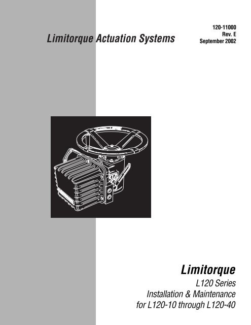
<strong>Limitorque</strong> Actuation Systems120-11000Rev. ESeptember 2002<strong>Limitorque</strong>L120 SeriesInstallation & Maintenancefor L120-10 through L120-40
Flow Control Division<strong>Limitorque</strong> Actuation SystemsL120 Series Installation & Maintenance Manual©2002 Copyright <strong>Limitorque</strong>. All rights reserved.Printed in the United States of America.DisclaimerNo part of this book shall be reproduced, stored in a retrieval system, or transmitted by any means, electronic,mechanical, photocopying, recording, or otherwise without written permission from <strong>Limitorque</strong>.While every precaution has been taken in the preparation of the book, the publisher assumes no responsibilityfor errors or omissions. Neither is any liability assumed for damages resulting from the use of the informationcontained herein.This document is proprietary information of <strong>Limitorque</strong> furnished for customer use ONLY. No other uses areauthorized without written permission of <strong>Limitorque</strong>.<strong>Limitorque</strong> reserves the right to make changes, without notice, to this document and to the products itdescribes. <strong>Limitorque</strong> shall not be liable for technical or editorial errors or omissions made herein; nor forincidental or consequential damages resulting from the furnishing, performance, or use of this document.The choice of system components is the responsibility of the buyer, and how they are used cannot be theliability of <strong>Limitorque</strong>. However, <strong>Limitorque</strong>’s sales team and application engineers are always available toassist you in making your decision.This manual contains information that is correct to the best of <strong>Limitorque</strong>’s knowledge. It is intended to be aguide and should not be considered as a sole source of technical instruction, replacing good technical judgment,since all possible situations cannot be anticipated. If there is any doubt as to exact installation, configuration,and/or use, call <strong>Limitorque</strong>‚ at (434) 528-4400. The latest revisions to this document are availableonline at http://www.limitorque.comIVL120 Installation & Maintenance Manual 120-11000 • Revision E • September 2002
Flow Control Division<strong>Limitorque</strong> Actuation SystemsTable of Contents1 Introduction 1-11.1 Purpose 1-11.2 User Safety 1-12 Product Capabilities & Features 2-12.1 Initial Inspection & Storage Instructions 2-12.2 Product Identification 2-22.3 Inspection & Recording 2-32.4 Storage Procedures 2-32.4.1 Short Term Storage (less than 1 year) 2-33 Unit Weights 3-14 Installation Instructions 4-14.1 Safety Precautions 4-14.2 Safety Practices 4-14.3 Initial Actuator Preparation 4-14.3.1 Mounting Base 4-24.3.2 Stem Acceptance 4-24.4 Torque Switch 4-24.4.1 Setting Torque Switch 4-24.4.2 Balancing Torque Switch 4-34.5 Geared Limit Switch 4-44.5.1 Setting Limit Switch 4-44.5.2 Setting Procedure 4-54.5.3 Combination of Contacts 4-64.6 Position Indication 4-64.6.1 Local Position Indication 4-64.6.2 Remote Position Indication 4-74.7 Optional Side-Mounted Handwheel 4-85 Operation 5-15.1 Electrical Start-Up 5-15.2 Manual Operation 5-45.3 Motor Operation 5-65.4 Torque & Travel Limiting 5-66 Maintenance 6-16.1 Lubrication 6-16.1.1 Lubrication Inspection 6-16.1.2 Factory Lubricant 6-16.2 Minimum Lubricant Qualities Required 6-26.3 Disassemble & Reassemble 6-26.4 Disassemble Unit Sizes L120-10, 20, and 40 6-36.5 Drive Sleeve & Housing Cover Disassembly 6-36.6 Torque Nut Disassembly (Drive 1 option) 6-4L120 Installation & Maintenance Manual 120-11000 • Revision E • September 2002 V
Flow Control Division<strong>Limitorque</strong> Actuation Systems6.7 Thrust Base Disassembly (Drive 2 Option) 6-56.8 Stem Nut Replacement—Thrust Base Applications 6-56.9 Reassembly 6-66.9.1 Declutch Assembly (L120-10) 6-76.9.2 Declutch Assembly (L120-20/40) 6-86.9.3 Install the Motor 6-87 How to Order Parts 7-18 Regulatory Information 8-1FiguresFigure 2.1 – L120-10 through 40 2-2Figure 4.1 – Micro-Switch Style Torque Switch & 600 Volt TorqueSwitch 4-3Figure 4.2 – Limit Switch 4-5Figure 4.3 – Setting the open & closed contacts 4-6Figure 4.4 – 1000 ohm Potentiometer 4-7Figure 4.5 – L120-10 parts list 4-8Figure 4.6 – L120-20 parts list 4-9Figure 4.7 – L120-40 parts list 4-10Figure 5.1 – L120-10 through 40 typical wiring diagram 5-2, 5-3Figure 5.2 – L120-10 through 40 drive sleeve & housing cover partsbreakdown 5-4, 5-5Figure 6.1 – L120-10 through 40 standard & extended drive sleeveassembly 6-4Figure 6.2 – L120-10 through 40 thrust base 6-5Figure 6.3 – L120-10 through 40 declutch assembly parts breakdown 6-7TablesTable 3.1 – Unit weights 3-1Table 4.1 – Required Rating for External Wiring 4-1Table 4.2 – Mounting Base Dimensions 4-2Table 4.3 – Stem Acceptance 4-2Table 4.4 – Maximum Number of Drive Sleeve Turns for Geared Limit Switches 4-4Table 5.1 – Required Rating for External Wiring 5-1Table 6.1 – Lubricant Weights 6-2VIL120 Installation & Maintenance Manual 120-11000 • Revision E • September 2002
Flow Control Division<strong>Limitorque</strong> Actuation Systems1 Introduction1.1 Purpose1.2 User SafetyThis Installation and Maintenance Manual explains how to install and maintain the L120-10, L120-20,and L120-40 actuators. Information on installation, disassembly, lubrication, and parts is provided.Safety notices in this manual detail precautions the user must take to reduce the risk of personalinjury and damage to the equipment. The user must read and be familiar with these instructionsbefore attempting installation, operation, or maintenance. Failure to observe these precautions couldresult in serious bodily injury, damage to the equipment, voiding of the warranty, or operational difficulty.Safety notices are presented in this manual in three forms:a WARNING: Refers to personal safety. Alerts the user to potential danger. Failure to follow warningnotices could result in personal injury or death.CAUTION: Directs the user’s attention to general precautions that, if not followed, could result inpersonal injury and/or equipment damage.NOTE: Highlights information critical to the user’s understanding of the actuator’s installation andoperation.L120 Installation & Maintenance Manual 120-11000 • Revision E • September 2002 1-1
Flow Control Division<strong>Limitorque</strong> Actuation SystemsThis page is intentionally blank.1-2L120 Installation & Maintenance Manual 120-11000 • Revision E • September 2002
Flow Control Division<strong>Limitorque</strong> Actuation Systems2 Product Capabilities & FeaturesL120 Series actuators operate without modification in any rising or non-rising stem application for linearaction valves.The actuators meet rigid safety requirements. The actuators are available in weatherproof,explosionproof, and submersible configurations.The actuators are compatible with a wide range of control options from stand-alone units with local pushbuttonto open standards-based DDC-100 networks with up to 250 actuators.The actuators are designed with integral control packages including plug-in interconnect boards thatincrease control functionality for stand-alone or networked units.Durable torque overload is provided in both directions of travel.2.1 Initial Inspection & Storage Instructionsa WARNING: Read this Installation and Maintenance Manual carefullyand completely before attempting to store the actuator. Be aware of the electrical hazards.L120 Installation & Maintenance Manual 120-11000 • Revision E • September 2002 2-1
Flow Control Division<strong>Limitorque</strong> Actuation Systems2.2 Product IdentificationThe actuator unit nameplate is located on the back of the unit opposite the limit switch compartment.The nameplate contains the following information:• <strong>Limitorque</strong> name• Point of Manufacture• Unit Size• Order Number• Serial Number• Customer Tagging• CE StampThe motor nameplate is located on the motor. The nameplate contains the following information:• ID Number• Start Torque• Run Torque• Enclosure Type• RPM• Volts• Full Load Amps• Locked Rotor Amps• Insulation Class• Duty• Horsepower• Service Factor• Phase• Cycles• Motor Code• Ambient Temperature• Connection DiagramFigure 2.1 – L120-10 through 40MotorHandwheelActuatorNameplate(hidden)DeclutchLeverLimit Switch/ControlsCompartmentHousing2-2L120 Installation & Maintenance Manual 120-11000 • Revision E • September 2002
Flow Control Division<strong>Limitorque</strong> Actuation Systems2.3 Inspection & RecordingUpon receipt of the actuator, inspect the condition of the equipment and record nameplate informationas follows:1. Carefully remove actuator from shipping carton or skid. Thoroughly examine theequipment for any physical damage that may have occurred during shipment. Ifdamaged, immediately report the damage to the transport company.2. Record the unit nameplate information for future reference; i.e. ordering parts,obtaining further information.2.4 Storage ProceduresNOTE: The following are our recommended storage procedures to retain maximum product integrityduring short-term storage. Failure to comply with recommended procedures will void the warranty.For longer-term storage, contact <strong>Limitorque</strong> for procedures and recommendations.2.4.1 Short-Term Storage (less than 1 year)Units are not weatherproof until properly installed on the valve or prepared for storage.Store units in a clean, dry, protected warehouse away from excessive vibration and rapid temperaturechanges. If the units must be stored outside, they must be stored off the ground, high enoughto prevent them from being immersed in water or buried by snow.1. Position the actuator in storage with motor and switch compartment horizontal.2. Connect the internal heaters (if supplied) or place desiccant in the switch compartment.3. Replace all plastic caps or plugs with pipe plugs and ensure that all covers are tight.4. If the actuator is mounted on a valve and the stem protrudes from the unit, a suitable stem covermust be provided.L120 Installation & Maintenance Manual 120-11000 • Revision E • September 2002 2-3
Flow Control Division<strong>Limitorque</strong> Actuation SystemsThis page is intentionally blank.2-4L120 Installation & Maintenance Manual 120-11000 • Revision E • September 2002
Flow Control Division<strong>Limitorque</strong> Actuation Systems3 Unit WeightsThe approximate L120 actuator weights are provided below:Table 3.1 – Unit weightsUnit Size Control Types Drive 1 Weight (lbs/kg) Drive 2 Weight (lbs/kg)Top HW Side HW Top HW Side HWlbs kg lbs kg lbs kg lbs kgL120-10 NCU 100 45 112 51 107 49 119 54BIC 115 52 127 58 122 55 134 61UEC/CLAMSHELL 140 64 152 69 147 67 159 72L120-20 NCU 140 64 158 72 153 69 171 78BIC 155 70 173 78 168 76 186 84UEC/CLAMSHELL 180 82 198 90 193 88 211 96L120-40 NCU 190 86 216 98 212 96 238 108BIC 205 93 231 105 227 103 253 115UEC/CLAMSHELL 230 105 256 116 252 114 278 126L120 Installation & Maintenance Manual 120-11000 • Revision E • September 2002 3-1
Flow Control Division<strong>Limitorque</strong> Actuation SystemsThis page is intentionally blank.3-2L120 Installation & Maintenance Manual 120-11000 • Revision E • September 2002
Flow Control Division<strong>Limitorque</strong> Actuation Systems4 Installation Instructions4.1 Safety Precautionsa WARNING: Read this Installation and Maintenance Manual carefully and completely beforeattempting to install, operate, or troubleshoot the <strong>Limitorque</strong> L120 actuator.a WARNING: Be aware of electrical hazards. Turn off incoming power before working on theactuator and before opening the switch compartment.a WARNING: Potential HIGH-PRESSURE vessel – Be aware of high-pressure hazards associatedwith the attached valve or other actuated device when installing or performing maintenance onyour L120 actuator. Do not remove the actuator mounting bolts when the actuator is mountedon a rising stem valve unless the valve is in the FULLY OPEN position and there is NOpressure in the line.a WARNING: Do not manually operate the actuator with devices other than installed Handwheeland Declutch Lever. Using force beyond the ratings of the unit and/or using additive forcedevices such as cheater bars, wheel wrenches, pipe wrenches, or other devices on theactuator Handwheel or Declutch Lever may cause serious personal injury and/or damage tothe actuator or valve.a WARNING: Do not work on the actuator while it is mounted on a torque-seated valve.4.2 Safety PracticesThe following checks should be performed to maintain safe operation of the L120 actuator.• Mount motors on a horizontal plane, if possible.• Keep the switch compartment clean and dry.• Keep the valve stem clean and lubricated.• Set up periodic operating schedule for infrequently used valves.• Carefully check for correct motor rotation direction. If the motor is driving the valve in the wrongdirection, interchange any two leads on three-phase motors or switch the armature leads on D.C.and single-phase motors.• Use a protective stem cover. Check valve stem travel and clearance before mounting covers onrising stem valves.• Verify all unit wiring is in accordance with the applicable wiring diagram, national and local codes,and Table 4.1.Table 4.1 – Required Rating for External WiringUp to: Use wire rated at least:40°C 60°C60°C 75°CL120 Installation & Maintenance Manual 120-11000 • Revision E • September 2002 4-1
Flow Control Division<strong>Limitorque</strong> Actuation Systems4.3 Initial Actuator PreparationReplace all molded plastic conduit and top protectors (installed for shipping purposes only) withpipe plugs when installation wiring is complete.4.3.1 Mounting BaseThe mounting hole sizes and quantities are as detailed in Table 4.2.Table 4.2 – Mounting Base DimensionsMounting HolesTap sizeUnit Size Quantity MSS ISOL120-10 4 3/8-16x0.88 M10x1.5x22.4L120-20 4 5/8-11x1.25 M16x2x32L120-40 4 5/8-11x1.25 M16x2x324.3.2 Stem AcceptanceThe maximum stem acceptance is provided in Table 4.3.Table 4.3 – Stem AcceptanceMaximum stem acceptanceDrive 2 Drive 1 Drive 1Tapped Bore KeyUnit size inch mm inch mm inch mmL120-10 1.25 32 1.00 25 1/4x3/32 8x6L120-20 2.25 57 1.875 47 1/2x3/16 14x9L120-40 2.625 66 2.125 52 1/2x3/16 16x104.4 Torque SwitchThe torque switch is designed to protect the actuator in open and close directions.CAUTION: Disconnect all incoming power before opening limit switch compartment or working onthe torque switch.• Do not use abrasive cloth to clean the contacts on the torque switch.• Do not torque seat 90° operation valves nor run them against the stops. This may causedamage to the valve.NOTE: If the actuator has “torqued out,” release torque buildup by operating the unit manually.4.4.1 Setting Torque SwitchThe torque switch was set at the factory according to customer-supplied information regardingnecessary torque or thrust output that was provided at the time of the order. However, if the settingneeds to be adjusted, follow the procedure below:4-2L120 Installation & Maintenance Manual 120-11000 • Revision E • September 2002
Flow Control Division<strong>Limitorque</strong> Actuation SystemsCAUTION: A torque switch limiter plate is provided on most units.• Removal or modification of the torque switch limiter plate will void the actuator warranty.• Do not exceed the setting indicated by this plate without contacting the <strong>Limitorque</strong>service department.• Installing or adjusting the torque switch with the operator in a loaded condition will resultin a loss of torque protection.Item letters correspond to Figure 4.1.1. Place the L120 actuator in manual mode.2. Release the load on the wormshaft spring pack.3. For open and close directions, loosen Screw (A) and move Pointer (B) to desired position. Ahigher number indicates a high torque and/or thrust output.4. Tighten Screw (A).5. Operate the valve electrically to seat valve and to ensure tight shut-off.6. Rebalance torque switch if required.Figure 4.1 – Micro-Switch Style Torque Switch & 600 Volt Torque SwitchMaximum StopSetting PlateBAMaximum StopSetting PlateBAOPEN-10-20BalancingScrewsBalancingScrewsIndex MarksB-10-20ACLOSEMountingScrewIndex MarksA BMountingScrewMicro-Switch Style Torque Switch600 Volt Torque Switch4.4.2 Balancing Torque SwitchItem letters correspond to Figure 4.1.1. Place the actuator in manual mode.2. Remove the load from the wormshaft spring pack.3. Note the open and close torque switch settings prior to re-installing the torque switch.4. Loosen screws (A) and position both pointers (B) at the #1 setting, tighten screw (A). In thisposition the index marks should be aligned.5. Loosen balancing screws and install the torque switch. The base of the torque switch should beflush against the compartment and the hole for the mounting screw should be aligned.6. Install the mounting screw.7. Tighten the balancing screws.L120 Installation & Maintenance Manual 120-11000 • Revision E • September 2002 4-3
Flow Control Division<strong>Limitorque</strong> Actuation SystemsCAUTION: The balancing screws should not be touched except during the balancing procedure.The switch is now balanced and ready for the pointers to be returned to theiroriginal settings.4.5 Geared Limit SwitchCAUTION: The geared limit switch is NOT preset at the factory and MUST be adjusted after theactuator has been mounted on associated equipment.• Disconnect all incoming power to the actuator prior to opening the limit switch compartmentand adjusting the switch.• Consult the relevant wiring diagram for limit switch contact development. All L120 units aresupplied with 16-contact limit switches - 4 switches on each of the 4 rotors. Two rotors are usedfor end of travel indication. The remaining two rotors may be adjusted for any intermediatepoint of travel.• Do not use abrasive cloth to clean the contacts on the limit switch.• Do not attempt to repair gearing in the limit switch. Replace entire gear frame assembly ifnecessary.4.5.1 Setting Limit SwitchNOTE: See chart below for maximum number of drive sleeve turns for each unit size. Theintermediate shaft (B), shown in Figure 4.2, may take a considerable number of turns before rotortrip occurs.Table 4.4 – Maximum Number of Drive Sleeve Turns for Standard 4-Gear and Optional 5-Gear LimitSwitchesUnit Size 4-Gear 5-GearL120-10 630 6300L120-20 740 7400L120-40 640 6400a WARNING: Potential Explosion Hazard. Do not use a variable speedelectric drill for setting the limit switch in an explosive environment.CAUTION: When setting the limit switch rotor segments (cams) using avariable speed electric drill, do not run drill at speeds higher than 200 RPM. Operating the drillat high speeds can damage the gearing within the limit switch.4-4L120 Installation & Maintenance Manual 120-11000 • Revision E • September 2002
Flow Control Division<strong>Limitorque</strong> Actuation SystemsSet the limit switch as follows. All item letters and piece numbers refer to Figure 4.2.Figure 4.2 – Limit Switch871B9A32654Piece Quantity Description1 1 Gear Frame Assembly2 2 8-Switch Contact Block Assy.3 12 Rotor Segment (short)4 4 Rotor Shaft5 4 Machine Screw6 4 Flat Washer7 4 Lock Washer8 8 Hex Nut9 4 Rotor Segments (long)Limit Switch4.5.2 Setting Procedure (Refer to Figure 4.2)1. Open the Compartment Cover (piece #200 of Figure 5.2).2. Put the actuator into manual operation. Use the handwheel to operate the valve in the “open”direction. While operating the valve, note the direction of the Intermediate Shaft (B)corresponding to the rotor or rotors to be set.3. When the valve is fully open, close it one turn of the handwheel to allow for coast of moving parts.CAUTION: For highly geared units, one turn of the handwheel will not allow for coast of movingparts. Refer to valve manufacturer setting requirements in these cases.4. Push in the Setting Rod (A) and turn one-quarter turn. The rod will latch in thisdepressed position.5. Refer to the applicable wiring diagram for contact development. The limit switch contact is closedwhen the rotor is engaged with the plunger. If the rotor to be set has not turned 90 degrees tooperate the plunger, turn the intermediate shaft in the same direction as noted in Step No. 2 untilthe rotor clearly trips the switches. This rotor is now set correctly.6. Before moving the valve, depress and turn the Setting Rod (A) one-quarter turn to the springreleased position. Insert a screwdriver into the intermediate shafts to ensure that they will notmove.CAUTION: Do not operate the valve when Setting Rod (A) is in a fully depressed position. Loss ofcontact setting will occur and the setting rod will be damaged.7. Operate the valve by handwheel to fully “close” position; reverse direction by one turn of the handwheelto allow for coast of moving parts.8. Set the other rotors by following Steps No. 4 through 6.L120 Installation & Maintenance Manual 120-11000 • Revision E • September 2002 4-5
Flow Control Division<strong>Limitorque</strong> Actuation SystemsFigure 4.3 – Setting the open & closed contactsClosedpositionOpenposition4.5.3 Combination of Contacts (Refer to Figure 4.2)The rotor segments can be separated and rotated through 90 degrees to give various combinationsof normally open or normally closed contacts to each rotor.1. Remove Nuts (piece #8) and Fillister Head Machine Screws (piece #5, for a total of 2 fasteners oneach side of the switch).2. Remove complete contact assembly from the back plate.3. Rearrange cams on the camshaft to produce the required combination of contacts.4. Replace contact assembly on back-plate (ensuring that the registers fit correctly) and secure withthe machine screw and nuts.5. Set limits according to the procedure above.4.6 Position Indication4.6.1 Local position indicationThe local dial position indicator is factory-selected to show valve position. The position indicator canonly be adjusted when mounted on the valve.To set the local position indicator:1. Disconnect all incoming power and remove Switch Compartment Cover (piece #200 of Figure5.2).2. Place the valve in the fully “close” position.3. Loosen the round head machine screw which holds the pointer in place, move the pointer to the“O” position, and re-tighten the screw.4-6L120 Installation & Maintenance Manual 120-11000 • Revision E • September 2002
Flow Control Division<strong>Limitorque</strong> Actuation SystemsThe indicator is now set.NOTE: The end-of-travel rotors of the geared limit switch activate “Flip-flop” type indicators. Thistype of indicator will require no further setting after the geared limit switch has been adjusted.4.6.2 Remote Position IndicationThe L120 actuator with a position transmitter (PT20SD) installed, transmits a 4-20mA output signalto a remote position indicator. The PT20SD responds to input of 1K (ohms) potentiometer and canbe powered by 18VAC or 24VDC. For more information on this transmitter, see <strong>Limitorque</strong>Publication 440-30001.NOTE: The pinion has been left disengaged to prevent damaging of rheostat prior to setting the valve.Set rheostat by turning pinion until the desired reading is obtained. Loosen the hex nut on the backof the rheostat and slide the rheostat in the direction of the idler pinion until pinions are engaged. Donot force engagement of the pinions. Re-tighten hex nut on back of the rheostat. Do not engagepinion until unit and valve have been set.To Calibrate Position Transmitter (PT20SD)1. Position the actuator to mid-travel; valve at 50% position.2. Disconnect the potentiometer wiring harness from the PT20SD board and measure the resistancefrom each end connection to the center connection on the potentiometer.3. Set the potentiometer to the correct resistance reading. Loosen the set screw that retains the spurgear on the potentiometer shaft and rotate the shaft until a reading of 500 ohms is achieved.4. Tighten the set screw and re-connect the wiring harness to the PT20SD.5. Run the actuator fully CLOSED.6. Calibrate ZERO position by adjusting the zero potentiometer until a 4mA output signal is read atterminal +VE and -VE.7. Run the actuator fully OPEN.8. Calibrate SPAN position by adjusting the span potentiometer until a 20mA output signal is read atterminals +VE and -VE.9. Repeat steps 5 to 8 and fine-tune as necessary.Figure 4.4 – 1000 ohm PotentiometerGearing1000 OHMSReceiver+-DC PowerSupply-+Customer EquipmentTypical Connection for a 1000 ohm PotentiometerL120 Installation & Maintenance Manual 120-11000 • Revision E • September 2002 4-7
Flow Control Division<strong>Limitorque</strong> Actuation Systems4.7 Optional Side-Mounted HandwheelFor unit sizes L120-10, 20, and 40, the handwheel can be mounted on the side as shown in thefollowing figures.Figure 4.5 – L120-10 parts list, attachment ratio 4.2:1182-2182-1182-3178 &179 181 180 177157-4157-3&157-6157-5158-1158-3160171161154169152164158-4Note: Apply Loctite 601/609to ID of Bearing CapPiece Quantity Description6 1 Housing Cover Shim42-11 1 O - Ring44 1 Quad Ring45 1 Pipe Plug150 1 Bevel Housing151 1 Bevel Housing Adapter152 1 Bearing Cap153 1 Bevel Gear154 1 Bevel Pinion Shaft157-1 4 Hex Head Cap Screw157-2 4 Lockwasher157-3 2 Soc Head Cap Screw157-4 1 Roll Pin157-5 2 Socket Head Cap Screw157-6 2 Lockwasher158-1 1 Quad - Ring158-2 1 O - Ring158-3 1 O - Ring158-4 1 Quad - Ring160 2 Ball Bearing161 1 Seal Insert164 1 Spacer169 1 Retaining Ring171 1 Grease Fitting177 1 Handwheel178 1 Hex. Head Cap Screw179 1 Lockwasher180 1 Key181 1 Retaining Washer182-1 1 Handwheel Spinner182-2 1 Sock. Head Cap Screw182-3 1 Hex. Jam Nut45157-1&157-244150 158-2 153151 6 42-11Drawing RE: 01-602-0479-44-8L120 Installation & Maintenance Manual 120-11000 • Revision E • September 2002
Flow Control Division<strong>Limitorque</strong> Actuation SystemsFigure 4.6 – L120-20 with side-mounted handwheel & parts list, attachment ratio 5.7:1182-2182-1179&178 181 180177182-3157-5157-1&157-2157-3&157-4158-1154161152158-3 169 160171157-6158-2Note: Apply Loctite 601/609to ID of Bearing Cap158-4Piece Quantity Description6 1 Housing Cover Shim42-11 1 O - Ring44 1 Quad Ring45 1 Pipe Plug150 1 Bevel Housing151 1 Bevel Housing Adapter152 1 Bearing Cap153 1 Bevel Gear154 1 Bevel Pinion Shaft157-1 4 Hex Head Cap Screw157-2 4 Lockwasher157-3 4 Hex Head Cap Screw157-4 4 Lockwasher157-5 1 Roll Pin157-6 2 Socket Head Cap Screw158-1 1 Quad - Ring158-2 1 O - Ring158-3 1 O - Ring158-4 1 Quad - Ring160 1 Ball Bearing161 1 Seal Insert169 1 Retaining Ring171 1 Grease Fitting177 1 Handwheel178 1 Hex. Head Cap Screw179 1 Lockwasher180 1 Key181 1 Retaining Washer182-1 1 Handwheel Spinner182-2 1 Sock. Head Cap Screw182-3 1 Hex. Jam Nut45153 150 151 44 6 42-11Drawing RE: 01-602-0476-4L120 Installation & Maintenance Manual 120-11000 • Revision E • September 2002 4-9
Flow Control Division<strong>Limitorque</strong> Actuation SystemsFigure 4.7 – L120-40 with side-mounted handwheel & parts list, attachment ratio 12:1182-2182-1182-3158-1Note: Apply Loctite601/609 to ID of 164Bearing Cap171158-5158-445157-1&157-2155163157-7161179&178 181 180160154157-6 152150157-5 158-2 153171156169177167Sect. Thru Pinion158-3151446 42-11157-3&157-4159164Handwheel Ratio 12:1Piece Quantity Description6 1 Housing Cover Shim42-11 1 O-Ring44 1 Quad-Ring45 1 Pipe Plug150 1 Bevel Housing Cover151 1 Bevel Housing152 1 Spur Gear Cover153 1 Bevel Gear154 1 Bevel Pinion155 1 Input Pinion Shaft156 1 Bevel Gear Adapter157-1 4 Hex Head Cap Screw157-2 4 Lockwasher157-3 4 Hex Head Cap Screw157-4 4 Lockwasher157-5 8 Socket Head Cap Screw157-6 2 Dowel Pin157-7 1 Socket Head Cap Screw158-1 1 Quad-Ring158-2 1 O-Ring158-3 1 Gasket158-4 1 Quad-Ring158-5 1 O-Ring159 1 Spur Gear160 1 Ball Bearing161 1 Seal Insert163 1 Ball Bearing164 2 Ball Bearing167 1 Key169 1 Retaining Ring171 1 Grease Fitting177 1 Handwheel178 1 Hex. Head Cap Screw179 1 Lockwasher180 1 Key181 1 Retaining Washer182-1 1 Handwheel Spinner182-2 1 Sock. Head Cap Screw182-3 1 Hex. Jam NutDrawing RE: 01-602-0460-44-10L120 Installation & Maintenance Manual 120-11000 • Revision E • September 2002
Flow Control Division<strong>Limitorque</strong> Actuation Systems5 Operationa WARNING: Do not manually operate the actuator with devices other than installed Handwheeland Declutch Lever. Using force beyond the ratings of the unit and/or using additive forcedevices such as cheater bars, wheel wrenches, pipe wrenches or other devices on the actuatorHandwheel or Declutch Lever may cause serious personal injury and /or damage to the actuatoror valve.CAUTION: Do not motor-operate the valve without first setting or checking the limit switchsetting and motor direction.• Do not force the declutch lever into hand operation. If the clutch does not easily engage, rotatehandwheel slowly while operating the declutch lever.• Do not alternately start/stop the motor to open or close a valve which is too tight for normaloperation.5.1 Electrical Start-Up1. Verify that the actuator has been correctly lubricated. This is particularly important if the actuatorhas been in long-term storage.2. Verify that the geared limit switch has been correctly set (see Section 4.5.1, Setting LimitSwitch).3. If the valve stem is not visible, remove the stem cover or handwheel cover plate to observe outputdirection of the drive sleeve.4. Engage manual operation and hand crank the valve well away from end of travel positions.5. Turn on power supply and push button to “open.”6. Check output rotation:• If phase rotation is correct, the valve should begin to open.• If valve begins to CLOSE, STOP Immediately. Incorrect phase rotation will lead to seriousdamage if the valve seats.7. Correct the phase rotation one of two ways:• Switch any two of the three power leads for three-phase power, or• reverse the armature leads for single-phase or dc power.The actuator should operate correctly and will be stopped at the end of travel positions by torqueor limit switch functions.Table 5.1 – Required Rating for External WiringUp to:Use wire rated at least:40°C 60°C60°C 75°CFigure 5.1 is a representation of a typical application and may not be applicable to your specificactuator. Please refer to the wiring diagram supplied with your actuator to confirm the actual equipmentsupplied.L120 Installation & Maintenance Manual 120-11000 • Revision E • September 2002 5-1
Flow Control Division<strong>Limitorque</strong> Actuation SystemsFigure 5.1 (one of two) – L120-10 through 40 typical wiring diagramGND 10GREEN/WHITEGREEN/WHITEL113T1L2L31211OOT2T3MOTORTAPSABEDEBLACKALTERNATETRANSFORMER TYPES15004804604153802600575550--3230VH1 AND H3TO L1H2 AND H4TO L2A B C D ECPT115V 18VFUSEFUSE18VREDWHITEYELYELBLUBLUWHITEOCCCBLACKBLACKBLACK7(7) (7C)3(3) (3C)RED RESGREENRESELEC HTRRGWHITEWHITEGREEN/WHITEBLACK21/22H1MTR HTRH219/20P25TH.OLP1BLACKPB2STOPSSOFFLOCAL REMOTEREDBROWNPB1OPENBLUE(5) (5C)4 18BLUEBLUE(4) (4C) RED (18) (18C)JUMPERSEE NOTE#5BLUEBLACKCBLUEWHITEP1OREDBROWNPURPLEPB3CLOSEYELLOWBLUEOYELLOWCBROWN8(8) (8C)1OPEN32 CLOSESTOPYELLOWRED17(17) (17C)1(1) (1C)YELLOWBLACKOPOT(OPTIONAL)YELLOWWHITECP1REDGRAYORANGEGRAYPINK456COMMONREMOTE INDREMOTE INDBLACK16BROWN17RED18Valve Shown Full Open PositionROTOROPENCLOSEINT.1INT.2CONTACT12345678910111213141516LIMIT SWITCH CONTACT DEVELOPMENTVALVE POSITIONFULLYABOPENFULLYCLOSEDFUNCTIONBY-PASS CIRSPAREIND LIGHTOPEN LIMITBY-PASS CIRSPAREIND LIGHTCLOSE LIMITSPARESPARESPARESPARESPARESPARESPARESPARE1718CLOSING TORQUE SWITCH INTERRUPTSCONTROL CIRCUIT IF MECHANICAL OVERLOADOCCURS DURING CLOSING CYCLEOPENING TORQUE SWITCH INTERRUPTSCONTROL CIRCUIT IF MECHANICAL OVERLOADOCCURS DURING OPENING CYCLENotes1. OPEN CONTACT2. CLOSE CONTACT3. SEE CERTIFICATION SHEET FOR VOLTAGE SUPPLIED.TRANSFORMER UNUSED WIRES TO BE SEPARATELYCOVERED WITH INSULATING HEAT SHRINK TUBING.4. ROTORS INT.1 & INT.2 CAN BE SET AT VALVEPOSITION FULL OPEN, FULL CLOSED OR ANYPOSITION IN BETWEEN AS INDICATED BYPOINTS A AND B.5. ADD JUMPER ON LS#8 BETWEEN TERMINALS (8)& (8C) FOR TORQUE SEATING VALVES.LegendO-OPEN CONTACTC-CLOSE CONTACTO OPENING COILC CLOSING COILCPT-CONTROL POWER TRANSFORMER+-MECHANICAL INTERLOCKTH.OL-THERMAL OVERLOAD CONTACTSR RED INDICATING LIGHTG GREEN INDICATING LIGHTSS-SELECTOR SWITCH(LOCAL-OFF-REMOTE)PB1-OPEN PUSHBUTTONPB2-STOP PUSHBUTTONPB3-CLOSE PUSHBUTTONELEC HTR-COMPARTMENT HEATERMTR HTR-MOTOR HEATERPOT-POTENTIOMETER (OPTIONAL, SEECERTIFICATION SHEET IF SUPPLIED)RES-LAMP RESISTORS˛5-2L120 Installation & Maintenance Manual 120-11000 • Revision E • September 2002
Flow Control Division<strong>Limitorque</strong> Actuation SystemsFigure 5.1 (two of two) – L120-10 through 40 typical wiring diagramWHTBLKGRN/WHTWHT ELECHTRBLKBLKL1F(NOTE#3)115V75VAPRIMARYCPTSECONDARY18V10VA1L2F218V10VAP1OREVERSING STARTERL1 T1L2 T2L3 T3P1CYEL/WHTBLU/WHTPURL3 T1L2 T2L1 T3PURT1T2T3P1MOTORTH.OLMTR HTRH1H2P2BLKFUSEWHTREDYELYELBLUBLUYELBLKBLUBLUBLKYELMOTOR GROUND LUGSW323 PUSHBUTTON STATIONFOR SIGNALCONVERTER USEWHEN SUPPLIED12BLUBLU1 BLK/WHT2 RED/WHTTORQUESWITCHOPEN18(18C) (18)CLOSE17(17C) (17)BLU/REDBLU/BLKYEL/REDYEL/BLKREDRWHT GRNGWHTBLKPB1OPENPB2STOPREDPB3CLOSEBLUBRNYELLIMIT SWITCHES(13C)(9C)139(13)(9)(14C)(10C)1410BLU/BLKBLU/REDLIMIT SWITCHES(5C)(1C)51(5)(1)(6C)(2C)62YEL/BLKYEL/REDOFFLOCAL REMOTEBRNORGREDBRNPUR(14)(15C)15(15)(16C)16(16)INT.2 ROTOR(10)(11C)11(11)(12C)12(12)INT.1 ROTORREDBLKYEL/REDYEL(6)(7C)7(7)(8C)8(8)CLOSE ROTOR(2)(3C)3(3)(4C)4(4)OPEN ROTORPOT(OPTIONAL)GRNBLKBLU/REDBLUE123GRNREDWHTLIGHTS1 BLKRESRESGRYPNK2BLUBLKBRNRED34PURYELBUTTONS1 BRNREMOTE OPENREMOTE CLOSEREMOTE STOPREMOTE COMMONSELECTOR SWITCH INREMOTE INDICATIONFOR SIGNALCONVERTER USE(WHEN SUPPLIED)SPAREINCOMING POWER GROUNDL3 INCOMING POWERL2 INCOMING POWERL1 INCOMING POWER12345678910111213BLUYELBRNORGGRYPNKBLK/WHTRED/WHTGRN/WHTL3L2L1BLKBRNREDGRN/WHTWHTWHTBLKBLKL2L1141516171819202122FUSESSPARESPAREPOT (CCW)POT (SWEEPER)POT (CW)P2H2H1CHASSISGROUNDL2FL1F234GRYPNKORGAUX. TERM.WIRE COLOR LEGENDBLUE : BLUYELLOW : YELPURPLE : PURBLACK : BLKORANGE : ORGBROWN : BRNWHITE : WHTRED : REDGREEN : GRNPINK : PNKGRAY : GRYCOLOR/STRIPEDElectrical CompartmentL120 Installation & Maintenance Manual 120-11000 • Revision E • September 2002 5-3
Flow Control Division<strong>Limitorque</strong> Actuation Systems5.2 Manual OperationPiece numbers refer to Figure 5.2.Counterclockwise rotation of the Declutch Lever (piece #9) causes the declutch actuator to lift theclutch sleeve out of engagement with the worm gear. Drive lugs on top of the clutch sleeve engagematching lugs in the Handwheel Adapter (piece #26) and then latches engage the clutch sleeve inthis position. The actuator is now in the handwheel driving option. Energizing the motor at this pointwill cause the latches to drop out and the spring loaded clutch sleeve re-engages with the lugs on theworm gear. The actuator is once more in motor operation.NOTE 1: The shift from manual operation to motor operation is automatic and does not requireexternal positioning of the declutch shaft.NOTE 2: If the declutch mechanism does not engage, rotate handwheel approximately 30-45° andattempt manual engagement. There is a chance that the lugs on the clutch sleeve (piece #19) andhandwheel adapter (piece #26) are not correctly aligned.Figure 5.2 (one of two) – L120-10 through 40 drive sleeve & housing cover parts breakdown2950241920212244232526432728421718Piece Quantity Description16 1 Ball Bearing17 1 Ball Bearing18 1 Drive Sleeve Bevel Gear19 1 H.W. Clutch Sleeve20 1 Worm Gear Lug Ring21 1 Worm Gear22 1 Spirolox Retainer23 1 Key24 1 Declutch Spring25 1 Drive Sleeve26 1 Handwheel AdapterPiece Quan27 1 Housing Cover28 1 Retaining Ring29 1 Handwheel33 1* Handwheel Cover Plat34 1* H.W. Cover Plate Gasket42 1 Seal Kit43 1 Quad-Ring44 1 Quad-Ring50 A/R Hardware* Not shown165-4L120 Installation & Maintenance Manual 120-11000 • Revision E • September 2002
Flow Control Division<strong>Limitorque</strong> Actuation SystemsFigure 5.2 (two of two) – L120-10 through 40 parts breakdown50313942384025050504250304619213101504242711305200475030034423735361592591054250Piece Quantity Description1 1 Housing2 1 Motor Adapter3 1 Electrical Compartment4 1 Seal Retainer5 1 Worm Shaft End Cap6 1** HSG. Cover Shim Set7 1 Declutch Shaft Assy.9 1 Declutch Lever10 1 Roll Pin11 1 Declutch Cap15 1 Worm Shaft Assembly19 1 Clutch Sleeve21 1 Worm Gear25 1 Drive Sleeve30 1 Nipple Flange31 1 Motor32 4** DowelsPiece Quantity Description35 1 Worm Shaft Gear36 1 Key37 1 Flexloc Nut38 1 Motor Pinion39 1 Key40 1 Stop Nut41 1** Washer42 1 Seals Kit46 1 O-Ring47 1 O-Ring50 1 Hardware Kit200 1 Compartment Cover300 1 Torque Switch305 1 Geared Limit Switch310 1 Unit Nameplate* L120-40 Only** Not ShownL120 Installation & Maintenance Manual 120-11000 • Revision E • September 2002 5-5
Flow Control Division<strong>Limitorque</strong> Actuation Systems5.3 Motor OperationThe actuator is always available for motor operation whenever the motor is energizedCAUTION: Do not force the declutch lever into motor operation. Lever willautomatically return to motor operation when the motor is energized.Reset the travel limit switches prior to motor operation if the unit has been dismantled or removedfrom the valve.Piece numbers refer to Figure 5.2.In motor operation, the Motor Gear Set (piece #35 & 38) drives the Wormshaft (piece #15) andWorm Gear (piece #21) which in turn rotates the Clutch Sleeve (piece #19) by means of driving thelugs. The clutch sleeve and worm gear may be assembled to produce either a “no lost motion” or“hammerblow” effect. The Drive Sleeve (piece #25) is keyed to the clutch sleeve and hence rotates,producing the required output rotary motion.5.4 Torque & Travel LimitingThe geared limit switch is driven by a bevel gear connected to the upper drive lugs of the clutchsleeve. The limit switch is directly connected to the output of the actuator. Once properly set, thelimit switch remains in step with the valve position regardless of electric or manual operation of the<strong>Limitorque</strong> actuator.The worm and wormshaft are supported by two rotating spring packs. As torque is generated bythe actuator, the worm moves axially against one of the spring packs. Each pack is precalibrated andhence a finite compression represents a finite torque output. Movement of the worm operates thetorque switch, which interrupts the power to the motor. The torque switch is adjustable and can beset to operate at pre-determined torque levels.5-6L120 Installation & Maintenance Manual 120-11000 • Revision E • September 2002
Flow Control Division<strong>Limitorque</strong> Actuation Systems6 Maintenance6.1 LubricationThe L120 series actuators have a totally sealed gear case, factory-lubricated with grease. The gearcase can be mounted in any position. However, mounting of the motor or the switch compartment inthe down position is not recommended. These mounting positions may result in the operator areabeing saturated with lubricant if the seal fails.No seal can remain absolutely tight at all times. Therefore, it is not unusual to find a very smallamount of weeping around shaft seals—especially during long periods of idleness such as storage.Using grease minimizes this condition as much as possible. If a small amount is weeping at start-up,remove it with a clean cloth. Once the equipment is operating on a regular basis, the weeping shouldstop.6.1.1 Lubrication InspectionInspect <strong>Limitorque</strong> L120 series actuators for correct lubrication prior to operating - particularlyfollowing a long storage period.Each application has its own effect on the actuator and the frequency of these inspections shouldbe based on the application and the operating experience. The following lubrication inspectionschedule is recommended until operating experience indicates otherwise.For Gear Case, inspect lubrication every 18 months or 500 cycles, whichever occurs first.During an inspection consider the following:• Quantity – Ensure there is enough lubricant so that the Worm and the Worm Gear are totallyimmersed in grease regardless of the position. To verify, pull out geared limit switch. Level ofgrease should be within 1/2" from bottom of geared limit switch opening.• Quality – Inspect lubricant for dirt, water or other foreign matter. If any one of these is found:1. Flush the actuator with a commercial degreaser/cleaner such as Exxon Varsol #18. Thisdegreaser/cleaner is not corrosive and does not affect the seal materials.2. Repack the actuator with fresh lubricant allowing room for grease thermal expansion.• Consistency – Ensure the lubricant is fluid approximating a standard NLGI-0 grade consistency orless. Thinners such as Amoco WAYTAC #31 oil may be added provided the volume of thinner doesnot exceed 20% of the total lubricant.6.1.2 Factory LubricantGear Case: The L120 series actuator gear case is factory-lubricated with EP-00 calcium complexbase grease, suitable for temperatures from -20°F (-29°C) to +250°F (+121°C).L120 Installation & Maintenance Manual 120-11000 • Revision E • September 2002 6-1
Flow Control Division<strong>Limitorque</strong> Actuation SystemsTable 6.1 – Specified Approximate Lubricant WeightsUnit Size Lbs. KgL120-10 3.3 1.5L120-20 6.1 2.8L120-40 8.1 3.7Geared Limit Switch: Permanently lubricated with Beacon 325. <strong>Limitorque</strong> does not recommenddisassembly of the gearbox.6.2 Minimum Lubricant Qualities RequiredThe standard lubricants used by <strong>Limitorque</strong> have been proven to be extremely reliable over years ofservice. <strong>Limitorque</strong> does not recommend a particular lubricant substitute for the standard lubricants;however, <strong>Limitorque</strong> does require the following lubricant qualities as a minimum.CAUTION: Do not mix lubricants of a different base chemical. Mixing lubricant bases may causelubricant properties to be ineffective.The Lubricant must:• contain an “EP” additive.• be suitable for the temperature range intended.• be water and heat-resistant and non-separating.• not create more than 8% swell in Buna N or Viton.• not contain any grit, abrasive, or fillers.• comply with a slump-prefer NLGI-0 grade.• not be corrosive to steel gears, ball, or roller bearings.• have a dropping point above 316°F (158°C) for temperature ranges of -20°F(-29°C) to +250°F (+121°C).6.3 Disassemble & ReassembleCAUTION: Turn off all power services before attempting to perform service on the actuator.•Remove the actuator from the valve for complex work. Minor work, such as replacing gearedlimit switch, torque switch, or motor, may be readily performed while the actuator is still on thevalve.• Potential High Pressure Vessel. Before removing or disassembling your actuator, ensure thatthe valve or other actuated device is isolated and is not under pressure.NOTE: If the actuator is fitted with a Thrust Base (piece #100 of Figure 6.2), it is possible to removethe actuator housing while leaving the base on the valve to accept valve thrust. However, it ispreferred that the valve be isolated from service and, if it is a rising stem, that the valve be fully open.6-2L120 Installation & Maintenance Manual 120-11000 • Revision E • September 2002
Flow Control Division<strong>Limitorque</strong> Actuation Systems6.4 Disassemble Unit Sizes L120-10, 20, and 40Unless otherwise noted, piece numbers refer to the Illustrated Parts Breakdown of Figure 5.2.1. Turn off power to the actuator.2. Remove electrical Compartment Cover (piece #200).3. Disconnect all electrical leads from the Torque Switch (piece #300) and Geared Limit Switch(piece #305). Ensure that all leads and terminals are clearly marked to facilitate reassembly.4. Remove two screws holding limit switch and one holding torque switch. Remove both items.5. Remove four bolts holding Motor (piece #31) and three bolts holding conduit Nipple Flange(piece #30). Remove motor, drawing motor leads through switch compartment.6. Remove Motor Pinion (piece #38) by removing Stop Nut (piece #40).7. Remove Worm Shaft Gear (piece #35), Flexloc Nut (piece #37), and Worm Shaft End Cap (piece#5) and draw complete wormshaft assembly from housing.NOTE: The wormshaft has been assembled at the factory to obtain the correct pre-load on thespring packs. Do not attempt to disassemble further. If the worm shaft is worn or damaged, it issuggested that the complete wormshaft subassembly be replaced. The actuator must be in motoroperation to remove the wormshaft assembly. When the wormshaft is partially out, the discsprings will hit the worm gear. Pull the declutch lever forward slightly without fully engaging thedeclutch mechanism and the wormshaft will come out.8. Remove Declutch Cap (piece #11).9. For unit size L120-10, completely withdraw the Declutch Assembly (piece #7 of Figure 6.3) fromthe housing. For unit sizes L120-20 and 40, remove Declutch Input Pinion (piece #12 of Figure6.3) followed by the Declutch Assembly (piece #7 of Figure 6.3).10. Remove Handwheel (piece #29) and Housing Cover (piece #27) and lift complete drive sleevesubassembly from housing.6.5 Drive Sleeve and Housing Cover DisassemblyPiece numbers refer to Figure 5.2.1. Remove Upper Ball Bearing (piece #17), Bevel Gear (piece #18), Declutch Spring (piece #24),Clutch Sleeve (piece #19), and Key (Piece #23).2. Remove Lower Ball Bearing (piece #16).3. Spirolox Retainer (piece #22) may now be removed by inserting small flat bladescrewdriver under the end of the ring and prying the first layer from the groove.Continue around the ring until it is free from the groove.4. Remove the Worm Gear (piece #21) and the Lug Ring (piece #20).5. Handwheel Adapter (piece #26) and Seal (piece #42) can be removed from Housing Cover (piece#27) by removing Retaining Ring (piece #28).L120 Installation & Maintenance Manual 120-11000 • Revision E • September 2002 6-3
Flow Control Division<strong>Limitorque</strong> Actuation Systems6.6 Torque Nut Disassembly (Drive 1 Option)For applications requiring torque only, the L120 series actuator can be supplied without the thrustbase option. The torque nut is driven by the drive sleeve lugs and held in place by the torque bushingconnector.Figure 6.1 – L120-10 through 40 standard & extended drive sleeve assembly9997259525969895Piece Quantity Description25 1 Drive Sleeve95 1 Torque Nut96 1 Torque Bushing Connector97 1 Torque Bushing Washer98 1 Retaining Ring99 1 Elastic Stop Nut183 1 Retaining Ring183183StandardExtendedUnless otherwise stated, piece numbers refer to Figure 6.1.Standard Drive SleeveTo remove the Torque Nut (piece #95), remove Retaining Ring (piece #183) and drop the torque nutout the bottom of the Drive Sleeve (piece #25 of Figure 5.2).Optional Drive Sleeve1. Remove the Handwheel (piece #29 of Figure 5.2), Handwheel Cover Plate (piece #33 of Figure5.2) and Gasket (piece #34) to provide access to the Elastic Stop Nut (piece #99).2. Remove the Elastic Stop Nut (piece #99) from the Rod (piece #1). The Torque Nut (piece #95) cannow be removed from the bottom of the Drive Sleeve (piece #25 of Figure 5.2).3. The Torque Bushing Connector (piece #96) can be removed from the torque nut by removing theRetaining Ring (piece #98).6-4L120 Installation & Maintenance Manual 120-11000 • Revision E • September 2002
Flow Control Division<strong>Limitorque</strong> Actuation Systems6.7 Thrust Base Disassembly (Drive 2 Option)Figure 6.2 – L120-10 through 40 thrust base105103104107A109, 112107105103104101102106NOTE: For the L120-10, use the same part number forpiece #107 and 107A. For the L120-20 and L120-40, usetwo different part numbers for piece #107 and 107A.108110, 111100Piece Quantity Description100 1 Base Housing101 1 Stem Nut102 1 Seal Retainer103 2 Needle Bearing104 2 Thrust Washer105 2 Thrust Washer106 1 O-Ring Seal107 1 Quad-Ring Seal107A 1 Quad-Ring Seal108 1 Gasket109 1 Grease Fitting110 4 Hex HD Cap Screw111 4 Lock Washer112 1 Relief FittingDrawing RE: 14-602-0219-2Piece numbers refer to Figure 6.2.1. If the Thrust Base (piece #100) option is present, remove the Seal Retainer (piece #102) followedby Stem Nut (piece #101).2. Remove the four Hex Head Cap Screws (piece #110) and the Lift Thrust Base from the housing.6.8 Stem Nut Replacement—Thrust Base ApplicationsThis section is only applicable to thrust base applications. Occasionally the operator stem nut may needreplacing if used in a threaded stem application on rising stem valves.a WARNING: Possible Hazardous Voltage. Turn power OFF before disassembling or removingthe actuator from the mounting base. This will prevent accidental start-up during service tothe unit.a WARNING: Potential High Pressure Vessel. Before removing or disassembling the actuator,ensure that the valve or other actuated device is isolated and not under pressure.Caution: The L120-10 through 40 thrust base contains lubrication.Ensure that EP-00 is replaced when reassembling thrust base.NOTE: Installation and retention of o-rings and quad rings can be eased by applying a smallquantity of EP grease to the ring during assembly.L120 Installation & Maintenance Manual 120-11000 • Revision E • September 2002 6-5
Flow Control Division<strong>Limitorque</strong> Actuation SystemsTo replace the stem nut:1. Disconnect all incoming power to the actuator.2. Remove actuator from the valve.3. Remove Seal Retainer (piece #102 of Figure 6.2) followed by stem nut, bearings, and seals.4. Check the fit of the new stem nut on the valve stem - ensure that the nut travels freely withoutbinding.5. Reassemble the thrust base and remount the actuator on the valve.6. Remount the actuator on the thrust base.7. Removing the actuator from the valve will change the limit switch settings. Reset the limit switchin accordance with Section 4.5.1, Setting Limit Switch.8. Reconnect power.9. Test for correct functioning.6.9 ReassemblyPiece numbers refer to Figures 5.1, 5.2, 6.1, 6.2, and 6.3.1. Install Lug Ring (piece #20) onto Drive Sleeve (piece #25) followed by the Worm Gear (piece#21). Ensure that the worm gear lugs engage with recesses on lug ring.2. Install Spirolox retainer (separate layers of retainer sufficiently to begin threading the retainer intothe drive sleeve groove. Continue threading until the retainer is firmly located in the groove).3. Install Key (piece #23) and Clutch Sleeve (#19).4. Add the Declutch Spring (piece #24), Bevel Gear (piece #18), Upper Bearing (piece #17), andLower Bearing (piece #16) to complete the assembly.5. Replace the drive sleeve assembly into main housing, and secure with the Housing Cover (piece#27). Ensure that all the seals are in place.6. Insert Wormshaft Assembly (piece #15) into the housing and locate the bearings in the housingjournals. Replace the Wormshaft Cap (piece #5).7. Install the Wormshaft Gear (piece #35) and Flex Loc Nut (piece #37).NOTE: It is recommended that a new flex loc nut be used during reassembly.6-6L120 Installation & Maintenance Manual 120-11000 • Revision E • September 2002
Flow Control Division<strong>Limitorque</strong> Actuation SystemsFigure 6.3 – L120-10 through 40 declutch assembly parts breakdown7842Declutch Stop7-17-2&7-384212Declutch Stop7-17-2&7-37A1142910L120-10 L120-20/401142910DeclutchActuatorLUGHandwheelClutchSleevePiece Quantity Description7* 1 Declutch Shaft Assembly L120-20/407A 1 Declutch Shaft Assembly7-1 1 Declutch Actuator7-2 & 7-3 1 Declutch Latch (left & right)8 1 Declutch Return Spring9 1 Declutch Lever10 1 Roll Pin11 1 Declutch Cap12* 1 Declutch Input Pinion42 1 Seal*L120-20/40 only6.9.1 Declutch Assembly (L120-10)8. Install Declutch Cap (piece #11) on the Declutch Shaft (piece 7A). Ensure that the return spring islocated correctly in the endcap.9. Replace Declutch Lever (piece #9) on the shaft with the lever against the stop.10. While holding the cap steady, rotate the declutch shaft against the spring tension until the holesin the shaft and lever align.11. Replace complete assembly in main housing. Ensure that the lug on theDeclutch Actuator (piece #7-1) fits into the groove on the Handwheel Clutch Sleeve (piece #19of Figure 5.2).12. Secure the declutch cap.NOTE: When the declutch lever is disengaged against the declutch stop (motoroperation position), the Declutch Actuator (piece #7-1) should not be in contact with the groove onthe Handwheel Clutch Sleeve (piece #19 of Figure 5.2).L120 Installation & Maintenance Manual 120-11000 • Revision E • September 2002 6-7
Flow Control Division<strong>Limitorque</strong> Actuation Systems6.9.2 Declutch Assembly (L120-20/40) (Refer to Figure 6.3)8. Install Declutch Cap (piece #11) on the Declutch Pinion Shaft (piece #12). Ensure that the returnspring is located correctly in the slots.9. Replace Declutch Lever (piece #9) on the pinion and against the stop.10. While holding the cap steady, rotate the Pinion Shaft (piece #12) against the spring tension untilthe holes in the shaft and lever align.11. Insert Roll Pin (piece #10).12. Slide Declutch Shaft (piece #7) into the housing, ensuring that the Declutch Shaft (piece #7) fitscorrectly into the groove in the Handwheel Clutch Sleeve(piece #19 of Figure 5.2).13. Install the declutch cap assembly into the housing, finding the nearest tooth on the internal spurgear which will allow the cap to be secured without placing tension on the Declutch Actuator(piece #7-1) causing it to rub against the groove in the Handwheel Declutch Sleeve (piece #19of Figure 5.2).6.9.3 Install the Motor (Refer to Figure 5.2)1. Install the Motor Pinion (piece #38) and Elastic Stop Nut (piece #40) onto the motor shaft. NOTE:The elastic stop nut should not be reused. It is recommended that a new nut be used duringreassembly.2. Install conduit Nipple Flange (piece #30) and Seal (piece #42) onto the conduit nipple in theflange and secure the motor. Secure the nipple flange.6.9.4 Lubrication Procedure1. Set unit on mounting base.2. Grease through the grease fitting located on the motor adapter, watch forgrease entering the housing cavity.3. Grease through the grease fitting in the housing cover until the adapter hasbeen completely greased and grease can be seen entering the drive sleeve compartment.4. Reposition the unit “nameplate down”.5. Finish filling housing cavity through the gear limit switch opening to within1/2" from the bottom of the gear limit switch opening.6.9.5 Install Geared Limit Switch, Torque Switch and Finish Assembly1. Install torque and limit switch into the switch compartment housing.NOTE: The limit switch must be reset before the actuator is placed back into service. The TorqueSwitch may need to be rebalanced. If required see Section 4.4.2, Balancing Torque Switch.2. Connect all electrical leads in the switch compartment.3. Replace the compartment cover, handwheel and thrust base, if applicable, to complete theassembly.6-8L120 Installation & Maintenance Manual 120-11000 • Revision E • September 2002
Flow Control Division<strong>Limitorque</strong> Actuation Systems7 How to Order PartsTo order parts or obtain further information about your <strong>Limitorque</strong> L120 valve actuators, contactyour local <strong>Limitorque</strong> distributor sales office, or:<strong>Limitorque</strong>5114 Woodall RoadP.O. Box 11318Lynchburg, VA 24506-1318Telephone (434) 528-4400Fax (434) 845-9736All inquiries or orders must be accompanied by the following information:1. Unit Size2. <strong>Limitorque</strong> Order Number3. <strong>Limitorque</strong> Serial NumberL120 Installation & Maintenance Manual 120-11000 • Revision E • September 2002 7-1
Flow Control Division<strong>Limitorque</strong> Actuation SystemsThis page is intentionally blank.7-2L120 Installation & Maintenance Manual 120-11000 • Revision E • September 2002
Flow Control Division<strong>Limitorque</strong> Actuation Systems8 Regulatory InformationDeclaration of ConformityApplication of Council Directive(s)89/336/EEC; EMC Directive98/37/EEC; Machinery DirectiveStandard(s) to which Conformity is DeclaredMachinery; EN 60204 EMC• Emissions; EN 50081-1&2, EN 55011, CFR 47• Immunity; EN 50082-1&2, IEC 801-3 & IEC 801-6 ESD; IEC 801-2• EFT/Bursts; IEC 801-4• Surge Immunity; IEC 801-5, ANSI/IEEE C62.41 Mains (power)• Harmonics; MIL-STD-462, Method CSO1 & CSO2Manufacturer’s Name<strong>Limitorque</strong>Manufacturer’s Address5114 Woodall RoadLynchburg, VA 24502Importer’s Name<strong>Limitorque</strong> InternationalImporter’s AddressAbex RoadNewburyBerkshire, RG14 5EYEnglandType & Description of EquipmentValve ActuatorsModel NumberL120 SeriesNoteTested with <strong>Limitorque</strong> products onlyI, the undersigned, hereby declare that the equipment specified above conforms to the above Directive(s) and Standard(s). List as follows:(Signature)Barry Morse(Full Name)Internal Sales Manager(Title)Newbury, EnglandPlaceNovember 1, 1999DateL120 Installation & Maintenance Manual 120-11000 • Revision E • September 2002 8-1
Flow Control Division<strong>Limitorque</strong> Actuation SystemsAustralian Distributor for <strong>Limitorque</strong>Acrodyne Pty Ltd14/11 Havelock RoadBayswater, Victoria 3153AustraliaPhone 03-8727-7800Fax 03-9729-8699