Limitorque MX - Acrodyne
Limitorque MX - Acrodyne
Limitorque MX - Acrodyne
- No tags were found...

Create successful ePaper yourself
Turn your PDF publications into a flip-book with our unique Google optimized e-Paper software.
Anatomy of <strong>MX</strong> Multi-turn Actuators<strong>Limitorque</strong> <strong>MX</strong> actuators respond to customer needs with advancedfeatures designed for ease of commissioning and use, as well as timeandmoney-saving operational benefits. What sets the <strong>MX</strong> apart is thecombination of control and reliability enabled by advanced <strong>Limitorque</strong>technology, plus superior ergonomics and human interfaces for speed,comfort, and ease of use.The reliable <strong>MX</strong> motor includes Class F insulationand thermal protection. It is designedspecifically for valve actuator service, with ahigh starting torque and low inertia to reducevalve position overshoot. Class H is availableas an option.Motor gear attachment allows the motor tobe removed in one assembly for fast, easyinspection, repair, and maintenance.<strong>MX</strong> actuators feature a LimiGard circuitmonitor that is designed for Fail/No-Actionprotection. LimiGard consists of dedicatedcircuitry that continually monitors themotor contactor, control relays, internallogic circuits, and external commandsignals to detect and alarm malfunctions.It now includes BIST with FrequencyDomain Analysis (FDA) for true predictivemaintenance.Plug-in connectors permit quick and easyreplacement of components.Double-sealed design provides a terminationchamber that is separate and sealed fromthe control chamber. Control componentsare never exposed to the elements duringsite wiring or because of a faulty cableconnection.External connection block has three powerterminals, a ground screw, and 54 controlscrew-type terminals to simplify commissioningand upgrades.Long-life gear set consists of hardened alloysteel rolled worm and bronze worm gearimmersed in an extended-life synthetic gearoil specifically developed for worm gearoperation. It is completely bearing-supported.Ductile iron thrust base is removable frommain actuator housing for easier valve installationand maintenance.High-strength, bronze alloy stem nut isremovable for machining to suit the valvestem.The control chamber includes an electroniccontrol, monitoring, and protection modulemounted on steel plate. Plug-in connectorsallow fast, error-free removal and replacementof the module.
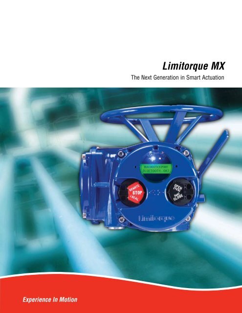
Control & DiagnosticsControl is expected in a smart actuator. The <strong>MX</strong> isnoted for simplifying valve control automation in threecritical methods of control:Switch KnobMagnetic FieldMagnetic Field• Calibration/set-up• Normal operation• Diagnostics & troubleshootingThe <strong>MX</strong> was the first non-intrusive actuator to equip Userswith LCD dialog screens in the language of their choice. <strong>MX</strong>now uses a graphical dot matrix display that improves thevisibility of the display. The use of this type of LCD permitsthe support of any language. In fact, in addition to English,Spanish, German, French, Italian, and Portuguese, the <strong>MX</strong> nowincludes four new languages – Mandarin, Russian, BahasaIndonesia and Katakana – with a capacity for even more. Theorientation of the text can be configured to rotate 180° anddiagnostic graphs displayed for clearer data collection.Simple “Yes” and “No” responses to dialog questionsconfirm the set-up of the <strong>MX</strong> via solid state Hall effectdevices in both knobs. No special tools or remote devicesare required. And the <strong>MX</strong> is “fit for service”, offering thewidest range of configuration menus of any non-intrusive,smart actuator.Unit “Opens”NOTE: Illustration forinformation only.Unit “Off”Hall effect devicesinterlocked toprevent operationDiagnostics should be easy to read and decipher. The <strong>MX</strong>diagnostic enhancements now offer a BIST (Built In SelfTest). The BIST feature is also designed into a state-of-theartcontrols platform that verifies and validates the integrityof its components. The result is a design which aids theUser in meeting the SIL (Safety Integrity Level) requirementsof IEC 61508. While an electronic actuator does not havea SIL rating by itself, placing a smart device into any plantsystem should enhance the ability of a given safety systemto achieve its preferred SIL rating. Any device which incorporatesfully developed BIST features provides assurance tothe User that the device has been designed with plant-widesafety and integrity of operation in mind.The “View Diagnostics” menu selections now includemore definitive routines which can isolate troubleshootingto “root cause” error codes. These root cause codes canbe used in conjunction with BIST. A well designed BISTbased system can do more than just report failures in theelectronic sub-systems. It can also determine failures or
Nothing exceeds <strong>Limitorque</strong> <strong>MX</strong> actuators for ease andcompatibility with valves of all typesValves<strong>Limitorque</strong> <strong>MX</strong> actuators have been designed toaccommodate today’s wide variety of valve designsand to meet international standards for valve andactuator interfaces, including ISO 5210 and MSSSP-102.<strong>MX</strong> mounted towedge gate<strong>MX</strong>/HBC mountedto butterfly valve<strong>MX</strong>/PT mountedto damper<strong>MX</strong> actuators are available in a wide variety of configurationsto accommodate various applications and valvedesigns:Direct mounting The <strong>MX</strong> can be directly coupledwith valves for torque-only applications. For thrustapplications, a separate thrust base is used.<strong>MX</strong>/B320 mountedto sluice gate<strong>MX</strong>/HBC The <strong>MX</strong> can be coupled to a PT or HBCworm gear reducer for operation of part-turn valves,such as butterflies, balls, plugs, and dampers. Thiscombination provides an output torque capacity of upto 136,000 ft-lb/184,280 N m.<strong>MX</strong>/B320 Rising stem valves may be operated byan <strong>MX</strong> coupled to a B320 bevel gear reducer. Thrustsup to 325,000 lb/1,445 kN and torque up to 12,000ft-lb/16,320 N m can be accommodated.CouplingsThrust actuator drive couplings:• Type A1 – Alloy bronze (thrust)• Type A1E – Extended bronze nutTorque-only actuator drive couplings:• Type B4 – Standard steel bushing• Type B4E – Extended steel bushing• Type B1 – Large fixed-bore keyway steel bushing (ISO 5210)• Type BL – Splined steel bushing for rising rotating stem valvesType A1Type A1E<strong>MX</strong> UnitType B1Type B4A1/A1EThrust BaseStandard Nut10Type B4EType BL
<strong>MX</strong> Control, Indication, Protection and Optional FeaturesStandard features• Direct-wired remote control – Wiring flexibility includesthe following standard alternatives to open-stop-close theactuator:° Four-wire – Valve can be opened, closed, or stopped.° Two-wire switched – Single open or closed contact;valve can be opened or closed, but not stopped.° Three-wire maintained – Two momentary contacts forself-maintained control. Valve can be opened or closedbut not stopped in mid-travel.° Three-wire inching – Two “push-to-run” contacts; valvecan be opened, closed, and stopped in mid-travel.• Monitor relay – Provides an N/O and N/C contactrepresenting “Actuator available for remote operation.”• Emergency Shutdown (ESD) – A remote, external ESDsignal may be applied to the actuator to move the valveto a predetermined user-configured shutdown position,overriding existing control signals.• User defined inputs – Three user defined inputs are supplied.• Inhibit signals – External signals may be used to inhibitactuator opening, closing, or both.• Control signals – The control signal can be either 24 VDCor optional 125 VAC; it can be sourced from the actuator orcustomer supply.• Status contacts (4) – May be set to represent up to 25actuator conditions.Protection features• Autophase protection and correction – Assures properopen/close directions and monitors and corrects phasing ifconnected improperly. Prevents operation if a phase is lost.• Jammed valve – Automatically initiates a forward/reversecycle to free jammed valves.• Instantaneous reversal protection – Incorporates the propertime delay between the motor reversals to reduce currentsurges and extend contactor life.• Motor thermal protection – A thermistor, placed within themotor, protects against overheating.Optional features• Alarm contacts – Up to eight latched contacts may be set torepresent up to 25 key actuator conditions.• Two-speed timer – A two-speed pulsing timer may beincorporated to support variable stroke times as configuredby the user.• Analog Position Transmitter (APT) – The APT is an internallypowered, non-contacting valve position transmitter thatprovides a 4-20 mA signal proportional to valve position.• Analog Torque Transmitter (ATT) – The ATT is a noncontacting,internally powered transmitter that provides a 4-20 mA signal that is proportional to actuator output torque.• Modutronic controller – The Modutronic controller positionsthe valve in response to an external 4-20 mA commandsignal. It includes automatic pulsing mode to preventovershoot at the set point. Parameters that may be set easilyduring configuration include proportional band, dead band,polarity, and action on loss of command signal.• Solid State Motor Reverser (SSMR) – An SSMR is availablewhen severe operating conditions demand continuousoperation.• Arctic temperature – The <strong>MX</strong> is suitable for installation andoperation in severely cold climates to -50°C (-58°F). Thereis no need for external heat sources to supplement theinternal power—the <strong>MX</strong> is predictable and reliable even inthe most rugged applications.• Control Station (CSE) – The CSE is a separate controlstation designed for the operation of inaccessible actuators.It is available with LEDs, Remote/Local and Open/Closeselector switches. The CSE may be powered by the actuatorinternal supply, provided wire resistance and other externalloads do not limit the available signal power presented tothe <strong>MX</strong>.• Isolation and Load Break Switches – Isolation and LoadBreak Switches can be supplied for the incoming threephasesupply to the actuator. These may be coupled directlyto the actuator for weatherproof (WP) applications only orsupplied separately for mounting by user. The enclosure issuitable for weatherproof or temporary submersion service.An explosion-proof (XP) isolation switch is also availablefor user mounting and is suitable for mounting with all <strong>MX</strong>actuators. Please contact factory for availability.12
• Negative Switching – When remote control systems requirethe negative pole of the circuit supply to be switched topositive earth, an optional board is supplied.• <strong>MX</strong> Quik – After the actuator has been powered by line powerfor one hour, it will automatically withstand most poweroutages while maintaining the correct state of the S or Rstatus contacts—even if the user repositions the actuatormanually with the handwheel. To maximize its self-powertime while the line power is lost, the actuator places itself inits lowest possible power usage mode. The LCD will darken(sleep mode) until it is activated for viewing. The LCD canbe activated by moving the black knob to OPEN (YES) or bymoving the actuator with the handwheel. After 10 seconds ofinactivity, the LCD will return to sleep mode. (Available 2007)Bluetooth capable optionsStandard low power wireless communication path to theactuator enables monitoring and configuration of the unit upto 10m in any direction via a Bluetooth equipped PC, PDA,smart cell phone, etc. FHSS (Frequency Hopping SpreadSpectrum) allows a reliable communication link even ina “noisy” environment and 128 bit data encryption can beenabled to protect the privacy of the link. <strong>MX</strong> Dashboardconfiguration / diagnostics tools can use the Bluetooth link asa means for communicating with the actuator. A visible blueLED in the controls LCD window on the face of the actuatorsignifies an active Bluetooth link to the actuator has beenestablished.Network CommunicationsThe <strong>MX</strong> provides a comprehensive network optionportfolio to the User. Network solutions are improvedwith the addition of DeviceNet to complement Modbus,Foundation Fieldbus H1, Profibus DP_V1/V2 and ProfibusPA. <strong>MX</strong> provides the User with predictable, reliable, andsafe operation for years to come, in applications whichare subject to the most rigorous requirements andenvironmental extremes.DDC Modbus (Distributed Digital Control)CommunicationDDC is Flowserve <strong>Limitorque</strong>’s digital communicationcontrol system that provides the ability to control andmonitor up to 250 actuators over a single twisted-pair cable.The communication network employs Modbus protocol onan RS-485 network and is redundant. Redundancy assuresthat any single break or short in the communication cablewill not disable any actuators. Each actuator has included anaddressable field unit that communicates over the twistedpair network and executes open, close, stop, ESD, and GOTO position commands. The field unit also communicatesall actuator status and alarm diagnostic messages over thesame communication network.Master Station II<strong>MX</strong> units equipped with DDC can be controlled via Flowserve<strong>Limitorque</strong>’s Master Station II. It includes;• Host interface – RS-232 or RS-485 with TCP-IP (Ethernet)as standard (Modbus protocol)• LED indicator for network status• Configurable polling sequence priority• Configurable bitmap to host• Redundant RS-485 network ports• High-level surge protection on network• Logging port for maintenance PCDDC Network• Single-ended loop (consult factory)• Modbus protocol• High speed – up to 19.2 k baud13
Foundation Fieldbus Communication<strong>MX</strong> can be fitted with Foundation Fieldbus protocol thatcomplies with the IEC 61158-2 Fieldbus H1 standard. Thefield unit device is able to support several topologies, suchas, point-to-point, bus with spurs, daisy chain, tree, or acombination of these. The FF device has network featuresthat include:• Link Active Scheduler that controls the system• High-speed communications up to 31.25 kbits/sec• Peer-to-peer communication• Input and output function blocks• Device descriptions• Network communication• Configurable by userLink Active Scheduler communication: Fieldbus segmentshave one active Link Active Scheduler (LAS) at a given time,which is the bus arbiter, and does the following:° Recognizes and adds new devices to the link° Removes non-responsive devices from the link° Schedules control activity in, and communicationactivity between, devices° Regularly polls devices for process data° Distributes a priority-driven token to devices forunscheduled transmissionsPROFIBUS DP V1/V2 Communication<strong>MX</strong> can be fitted with Profibus DP_V1/V2 protocol field unitsthat comply with EN50170 Fieldbus Standard for RS-485communications. The device supports several topologies,such as, point-to-point, bus with spurs, daisy chain, tree, ora combination of these. The PB device has network featuresthat include:• High-speed communications up to 1.5 m/bits/s• Master-to-slave and peer-to-peer communication• Stand-by communication channel• Analog & digital input and output function blocks• Device descriptions configurable by userHigh-Speed Data Exchange – Startup SequencePROFIBUS PA CommunicationA Profibus PA protocol is available and complies withEN50170 Fieldbus Standard and Fieldbus physical layerper IEC 61158-2 for communications. The device supportsseveral topologies, such as point-to-point, bus with spurs,daisy chain, tree, or a combination of these. The PB devicehas network features that include:• High-speed communications up to 31.25 kbits/s withManchester coding• Peer-to-peer communication• Bus powered for 9-32 VDC and 15 mA per actuator• Stand-by communication channel• Analog & digital input and output function blocks• Device descriptions• Configurable by userDeviceNetDeviceNet complies with CAN based protocol and providesthe following features:• DeviceNet Group 2 Server implementation.• Bus Powered Network Interface allows power alarminformation to be communicated when actuator looses mainpower. The actuator does NOT drop off the network when3-phase power is lost.• Standard Polled I/O Connection• Standard Bit Strobed I/O Connection• Standard Change of State / Cyclic I/O Connection• Standard explicit connections defined as:° Various Assembly Objects and sizes that allow thenetwork user to determine how much data to transferto accommodate network installation data throughputrequirements.° Automatic BAUD rate detection.° Node Address configurable via local setup menu, or viathe remote network user.° Broadcast or group network originated ESD support.14• Power ON / Reset – Power On / Reset of master or slave• Parameterization – download of parameters into field device(selected during configuration by the user)• I/O Configuration – download of I/O configuration into thefield device (selected during configuration by the user)• Data Exchange – cyclic data exchange (I/O Data) and fielddevice reports diagnostics
<strong>MX</strong> Series Performance Ratings for Units 05–140<strong>MX</strong>-05 through <strong>MX</strong>-40 (three-phase: 50 Hz/380, 400, and 415 Volt: 60 Hz/208, 230, 380, 460, 525, 575 Volt)<strong>MX</strong>-85 through <strong>MX</strong>-140 (three-phase: 50 Hz/380*, 400, and 415 Volt: 60 Hz/380, 460, 525, 575 Volt) *380/50 multiply by 0.9<strong>MX</strong>-05 <strong>MX</strong>-10 <strong>MX</strong>-20 <strong>MX</strong>-40 <strong>MX</strong>-85 <strong>MX</strong>-140Output Speed (RPM)Rated Output Torque60 Hz 50 Hz ft-lb N m ft-lb N m ft-lb N m ft-lb N m ft-lb N m ft-lb N m181555 75 125 170 225 305 440 597 N/A N/A N/A N/A262255 75 125 170 225 305 440 597 850 1153 1500 2036403355 75 125 170 225 305 440 597 1225 1662 1700 2307524355 75 125 170 225 305 440 597 1150 1561 1600 2171776548 65 107 145 178 241 345 468 850 1153 1200 1628100 131 1 84 110 1 39 53 89 121 148 201 286 388 600 814 739 1003155 170 1 127 143 1 41 56 89 121 140 190 260 353 450 611 650 882200 165 34 46 73 99 114 155 210 285 N/A N/A N/A N/ANote 1: <strong>MX</strong>-85 and <strong>MX</strong>-140lb kN lb kN lb kN lb kN lb kN lb kNThrust Ratings (lb/kN) 8000 35 15000 66 25000 111 36000 160 50000 222 75000 333lb kg lb kg lb kg lb kg lb kg lb kgWeights (lb/kg) 52 24 65 29 109 49 133 60 250 114 300 136Maximum Stem CapacityType A Couplings in. mm in. mm in. mm in. mm in. mm in. mmType A1 1.26 32 1.57 40 2.36 60 2.64 67 3.50 88 3.50 88Type A1E (Extended Nut) 1.26 32 1.57 40 2.36 60 2.64 67 3.50 88 3.50 88Type B Couplings (Torque in. mm in. mm in. mm in. mm in. mm in. mmOnly) 2Type B4 1 25.4 1.25 30 1.94 50 2.2 55 2.88 73 2.88 73Type B4E (Extended) 0.75 19 0.91 22 1.56 41 1.78 46 2.25 57 2.25 57Type B1 (Fixed Bore) 3 N/A 42 N/A 42 N/A 60 N/A 60 N/A N/A N/A N/AType BL (Splined) 6 & 38 Splines 6 & 38 Splines 6 & 36 Splines 6 Splines N/A N/A N/A N/AMaximum Bore and Keyway in. mm in. mm in. mm in. mm in. mm in. mmMaximum Bore (B4) 1 25 1.25 30 1.94 50 2.2 55 2.88 73 2.88 73Maximum Keyway 1/4 sq. 8 x 7 1/4 sq. 10 x 8 1/2 x 3 ⁄8 14 x 9 1/2 x 3 ⁄8 16 x 10 3/4 x 1/2 20 x 12 3/4 x 1/2 20 x 12Maximum Bore (B4E) .75 18 0.91 22 1.56 41 1.78 46 2.25 56 2.25 56Maximum Keyway 3⁄16 sq. 6 x 6 1/4 sq. 8 x 7 3⁄8 sq. 12 x 8 1/2 x 3 ⁄8 14 x 9 1/2 x 3 ⁄8 16 x 10 1/2 x 3 ⁄8 16 x 10Note 2: Maximum bores for Type B couplings may require rectangular keys.Note 3: Available in ISO base only.<strong>MX</strong>-05 <strong>MX</strong>-10 <strong>MX</strong>-20 <strong>MX</strong>-40 <strong>MX</strong>-85 <strong>MX</strong>-140Mounting Base (MSS SP-102/ISO 5210) FA10/F10 FA10/F10 FA14/F14 FA14/F14 FA16/F16 FA25/F25Handwheel Ratio (STD/Optional) Direct Direct/8:1 Direct/12:1 Direct/24:1 16/48 16/48Side-Mounted Handwheel Efficiencies N/A 52% 54% 51% 53%/51% 4 53%/51% 4Note 4: Efficiencies for <strong>MX</strong>-85 and 140 are 51% with SGA and 53% without SGA.15
<strong>MX</strong> Standard Features<strong>Limitorque</strong> <strong>MX</strong> electronic valve actuators are designed for theoperation of ON-OFF and modulating valves. They include athree-phase electric motor, worm gear reduction, absoluteencoder, electronic torque sensor, reversing motor contactor,electronic control, protection and monitoring package, handwheelfor manual operation, valve interface bushing, 32-character LCD,and local control switches—all contained in an enclosure sealedto NEMA 4, 4X, 6, and IP68. Explosionproof (XP) enclosures canalso be provided when required. All <strong>MX</strong> actuators comply withapplicable European Directives and exhibit the CE mark.Gear drive• Bearing-supported worm gear reduction, lubricated with anextended-life synthetic oil, Mobil SHC 632.• A FGL (Food Grade Lube) is available as an option – DowMolykote.• Artic lube is available – Petro Canada Syngear 75W-90.Motor• Three-phase squirrel cage induction type, designed for valveactuator service. Supplied with a solid state thermistor toprevent damage due to temperature overloads.• Available as 50 Hz/380, 400, or 415 Volts and 60 Hz/208,230, 380, 460, 525, or 575 Volts.• Bolt-on design with plug-in connector allows easy removal.Controls• Power and logic circuit boards, a control transformer,and fuses are mounted to a steel plate that is attachedin the control compartment with captive screws. Plug-inconnectors allow for easy removal.• Reversing contactor is interlocked to prevent simultaneousenergizing of the open and closed coils and supplied withcontrol logic to extend contactor life by inhibiting highcurrent surges caused by rapid motor reversals.• Phase correction circuit detects and corrects motor rotationfaults caused by incorrect site wiring and also preventsoperation of the motor due to a loss of phase.• Control transformer powers actuator controls and minimalexternal loads from the site’s three-phase power supply. Itincludes vacuum-impregnated coils for moisture resistanceand dual fuse protection.• Internal 24 VDC power supplies for remote control functionsare fuse protected. 110 VAC is an available option.• Terminals for optional auxiliary 24 VDC supply provide theability to externally power the electronic control package andgraphical LCD display without AC power.• LimiGard is protection circuitry that continually monitorsmotor controls, internal logic circuits, and externalcommand signals to all but eliminate the possibility ofactuator malfunction due to internal component failures orerratic command signals.Control panel (local control and indication)• 32-character graphical LCD displays valve position(0–100%), current actuator status, and provides dialog forcalibration. Available languages include English, Spanish,German, French, Italian, Portuguese, Mandarin, Russian,Bahasa Indonesia, and Katakana.• Green, red, and yellow LEDs for local position indication;LOCAL-STOP-REMOTE and OPEN-CLOSE switches providelocal valve control and are magnetically coupled to solidstate Hall effect devices under the controls cover forenvironmental security.• LOCAL-STOP-REMOTE switch is padlockable in eachposition.• OPEN-CLOSE switch is spring-return-to-center and may beconfigured for maintained or push-to-run (inching) control.16
Remote control• Remote control can be configured using two, three, or fourwires for open-stop-close control.• Connections are also supplied for ESD (EmergencyShutdown) and inhibit movement commands. The ESDsignal will override existing control signal and send thevalve to a pre-set position.Remote indication• Four latched contacts (configurable as N/O or N/C andfor any valve position) provide remote indication of valveposition.• Alternately, the contacts may be configured to representother actuator status: overtorque, motor thermal overload,power off, manual operation, local selected, etc.Monitor relay• Will de-energize when the actuator is not available forremote operation. Both N/O and N/C contacts are included.Calibration• Simple, non-intrusive calibration of all actuator settingsthrough the control panel. A password may be userconfiguredto prevent unauthorized changes. No tools arerequired.Position sensing• 18-bit, optical, 100% repeatable absolute encoder formeasurement of valve position. Open and closed positionsare stored in permanent, non-volatile memory. The encodermeasures valve movement at all times, including both motorand handwheel operation. Position resolution is betterthan 0.1% for valves requiring 50 turns or more, with amaximum of 10,000 drive sleeve turns.Torque sensing• A microprocessor calculates output torque from motorspeed, voltage, and temperature. Torque limit may be setfrom 40–100% of rating in 1% increments. A boost circuit isincluded to prevent torque trip during initial valve unseatingand in cold climates. A “Jammed Valve Protection” feature,with automatic retry sequence, is included to de-energizethe motor if the output torque requirement exceeds theboost torque.Terminal compartment• Separately sealed terminal chamber for connection of sitewiring protects actuator components from the environment.Internal sealing is suitable for NEMA 4, 6, and IP68.Includes three power terminals, a ground screw, and 54control screw-type terminals.Conduit entries• Three conduit entries, available as NPT, mm, or PG.External corrosion protection• Primed using high solids epoxy-ecoat and powder topcoated,royal blue color with a DFT of 1–3 mils. The coatingis suitable for an ASTM B117 salt spray test of 1500 hours.• External fasteners are high-strength carbon steel, hexavalentchromate-coated, and top-coated with a high-strength, highendurancepolymer coating.Handwheel• Handwheel with padlockable, manual declutch lever isprovided for manual operation.17
<strong>MX</strong> SpecificationsThe <strong>MX</strong> is the most rigorously tested non-intrusive actuatorin the industry and complies with all pertinent global requirements.Please contact the factory should your requirementsexceed the listed parameters.Global certificationsStandard Non-hazardous certifications - The normaloperating temperature range for weatherproof applications isfrom -30°C to +70°C (-22°F to +158°F). Options are availableto -50°C (-57°F).• FM – NEMA 3, 4, 4X and 6.• CSA – Type 3, 4, and 6.• IEC – IP 68 to 15 m for 96 hours.• Submersion – NEMA 6 (6 ft–30 min), IEC529, IP68 (15m–96 h), <strong>Limitorque</strong> specification (20 ft–24 h)• Saliferous (Salt) spray – 1500-hour test per ASTM B117-1985.Standard Explosionproof certifications - The normal operatingtemperature range for explosionproof applications isfrom -30°C to +65°C (-22°F to +149°F). Options are availableto -50°C (-57°F) for FM and CSA.• FM – Class 1, Division 1, Group B, C, and D. Class II/III,Division 1, Group E, F, and G – T4• CSA – Class 1, Division 1, Group C and D. Class II/III,Division 1, Group E, F, and G – T4• ATEX – EEx d IIB T4 ATEX II 2 G, CENELEC Norm EN50014and EN50018– EEx d IIC T4 ATEX II 2 G, CENELEC Norm EN50014 andEN50018– EEx de IIB T4 ATEX II 2 G, Increased Safety, CENELECNorm EN50014, EN50018, EN50019– EEx de IIC T4 ATEX II 2 G, Increased Safety, CENELECNorm EN50014, EN50018, EN50019• Anez – Ex d IIB T4 & Ex de IIB T4 and Ex d IIC T4 & Ex deIIC T4Wiring• All internal wiring is flame resistant, rated -40°C to 105°C(-40°F to 221°F), and is UL listed.Valve interface• Mounting base conforms to MSS SP-102 or ISO 5210/1/2/3as required. Steel torque bushings (type B) and bronzethrust nuts (type A) are removable for machining. Refer torating chart on page 10 for a listing of couplings available.Design life & endurance• Design Life - One million drive sleeve turns is consideredtypical life expectancy under normal operating conditions inapproved ambient working environments.• Endurance – 50 million collective drive sleeve turns ofendurance testing were performed on the <strong>MX</strong> for proof ofdesign.• AWWA C540-02 – “Standard For Power ActuatingDevices For Valves and Sluice Gates” – 5,000 cycles withconfirmation of specified torque and position accuracy.Diagnostic featuresDiagnostic facilities are displayed on the LCD by accessingthe diagnostic menu or the <strong>MX</strong> Dashboard . It includes:motor data (voltage, current, phase rotation, and temperature),hardware status, and identification (tag, serial order,and software revision), torque profile (comparison oflast torque to baseline), and operations log (total turns,contactor operations, valve stroke time, and handwheeloperations). Diagnostics also includes a Frequency DomainAnalysis (FDA) feature. The FDA methodology capturestorque, position or speed values at regular time intervalswhile the actuator is motoring, and calculates the resultingdata set with a Fast Fourier Transform (FFT). The resultinginformation can be used to isolate any components in themechanical drive train that may exhibit excessive wear ormay effect normal actuator operation. FDA and resultantfault indications can be displayed via the graphical LCD. Theactuator also contains the ability for diagnostics informationto be downloaded to a PC or PDA via both IRDA andBluetooth ports utilizing <strong>MX</strong> Dashboard.18
Distribution NetworkVictoria & TasmaniaACRODYNE Pty Ltd14/11 Havelock RoadBayswater, VIC 3153Phone: (03) 8727 7800Facsimile: (03) 9729 8699 N.S.W.Multivalve144 Fern StreetIslington, NSW 2229Phone: (02) 4961 4641Facsimile: (02) 4961 4643FCD LMENBR2302-00 Printed in USA.South AustraliaV & I AustaliaUnit 15, 25 Nylex AvenueSalisbury South, SA 5106Phone: (08) 8281 8299Facsimile: (08) 8281 8719Western AustraliaZedflo AustraliaUnit 1, 8 Baretta RdWangara, WA 6947Phone: (08) 9409 7566Facsimile: (08) 9409 7153New ZealandAsmuss HJ & Co6 Gabador PlaceMt Wellington, AucklandPhone: +64 9573 0099Facsimile: +64 9573 5590