A R I S A n t r i e b e u n d S t e u e r u n g e n G m b H
ARIS Antriebe und Steuerungen GmbH - Acrodyne
ARIS Antriebe und Steuerungen GmbH - Acrodyne
- No tags were found...

Create successful ePaper yourself
Turn your PDF publications into a flip-book with our unique Google optimized e-Paper software.
A n w e n d u n g e nK u n d e nnnnnnnnnnDosierpumpenArmaturenIndustriebrennerKlima- undLüftungsanlagenKesselanlagenLackierstraßenJalousienIndustrieöfenAutoklavennnnnnnnnnIndustrieller AnlagenbauChemische IndustrieUmweltindustriePharmaindustrieLebensmittelindustrieHeizungsbauFeuerungsbauStadtwerkeVersorgerA P P L I C A T I O N SC U S T O M E R SnnnnnnnnnMetering pumpsValvesIndustrial burnersAir conditioningand ventilating plantBoiler systemsPainting linesLouversIndustrial furnacesAutoclavesnnnnnnnnnIndustrial plant engineeringChemical industryEnvironment engineeringindustryPharmaceutical industryFoodstuff industryHeating engineeringFurnace engineeringMunicipal worksUtility companiesA P P L I C A T I O N SC L I E N T SnnnnnnnnnPompes de dosageRobinetteriesBrûleurs industrielsInstallations de climatisationet d’aérationInstallations de chaudièreChaînes de vernissageStoresFours industrielsAutoclavesnnnnnnnnnConstruction d’équipementsindustrielsIndustrie chimiqueIndustrie écologiqueIndustrie pharmaceutiqueIndustrie agroalimentaireInstallations de chauffageConstruction industriellede chauffeEntreprises communalesd’électricitéServices publics d’alimentation
. . . R I C H T U N G Z U K U N F T„ARIS Antriebe und Steuerungen“ startetebereits 1973 in Bonn mit dem Vertrieb vonkompakten Antrieben. Nach rasanter Expansionwechselte ARIS zum heutigen StandortHennef. Die Produktion und Montage erfolgtmittlerweile im zugehörigen Werk Oerlinghausen.Im Zuge weiterer Expansionsmaßnahmenzieht ARIS im April 2007 nach Troisdorf-Spichin die neuen Geschäftsräume ein. Weitere Investitionensind geplant, um weiterhin erfolgreichRichtung Zukunft zu steuern....FOCUS ON THE FUTUREIn 1973, „ARIS Antriebe und Steuerungen“began with the distribution of compact actuatorsin Bonn. Following a meteoric expansion,ARIS moved to the present location in Hennef.Production and assembly are now carried outin the affiliated Oerlinghausen factory. In thecourse of further expansion steps, ARIS willbe moving to new business premises in Troisdorf-Spichin April 2007. Other investmentmeasure are planned so that we can continueto focus successfully on the future.. . . V E R S L’ A V E N I REn 1973 déjà, la société „ARIS Antriebe undSteuerungen“ a commencé à commercialiserdes servomoteurs compacts à Bonn. Aprèsune expansion fulgurante, ARIS s’est installéeà Hennef où se trouve encore actuellement lesiège de la société. La production et le montagesont maintenant effectués à l’usine à Oerlinghausen.Du fait de mesures d‘expansion supplémentaires,ARIS déménagera en avril 2007dans ses nouveaux locaux à Troisdorf-Spich.D’autres investissements sont prévus pourgarantir aussi à l’avenir le succès del’entreprise.
. . . R I C H T U N G K O M P E T E N Z. . . F O C U S O N R E L I A B I L I T Y. . . V E R S L A C O M P É T E N C EDie sichere Kontrolle über Gase, Flüssigkeitenund Feststoffe ist in industriellen Anlagenextrem wichtig. Hier darf nichts dem Zufallüberlassen werden. Eine zuverlässige Steuerungist unverzichtbar. Stellantriebe von ARISsind perfekt geeignet zum Bewegen, Regelnund Steuern von Armaturen in allen Industriebereichen.Secure control of gases, liquids and solidmatter is extremely important in industrialinstallations. Nothing can be left to chancein this area. A reliable control system iscrucial. ARIS actuators are perfectly suitedto move, regulate and control valves in allindustrial areas.Le contrôle fiable des gaz, des liquides et desmatières solides est extrêmement importantdans les installations industrielles. Dans cedomaine, rien ne doit être laissé à l’hasard.Une commande fiable est indispensable. Lesservomoteurs d’ARIS conviennent parfaitementà l’actionnement, au réglage et à lacommande des robinetteries dans tous les domainesindustriels.M I T A R I S S I C H E R S T E U E R N . . .. . . R I C H T U N G V I E L F A LT. . . F O C U S O N D I V E R S I T Y. . . V E R S L A D I V E R S I T ÉDank beständiger Marktorientierung undInnovationsfreudigkeit bietet ARIS Ihnenheute ein großes Spektrum an elektrischenund pneumatischen Stellantrieben, elektronischenRegelkomponenten, motorgesteuertenArmaturen und eine äußerst umfangreichePalette an Zubehörteilen. Ob Standard-Komponentenoder spezielle explosionsgeschützteStellantriebe – Sie haben die Wahl.Thanks to our continual sensitivity to marketrequirements and to our innovative drive ARIScan now offer you a large variety of electricand pneumatic actuators, automatic electroniccontrol components, motor-controlledvalves - and a particularly extensive range ofaccessories. Whether you require standardcomponents or special explosion-proof actuators– the choice is yours.Grâce à une orientation permanente auxbesoins du marché et un esprit d’innovation,ARIS vous propose aujourd’hui une largegamme de servomoteurs électriques etpneumatiques, des composantes de réglageélectroniques, des robinetteries commandéespar moteur et un large éventail d’accessoires.Qu’il s’agisse des composantes standard oudes servomoteurs spécialement protégés contreles explosions, vous avez le choix.ARIS garantiert sichere, stabile Produkte. Das ist nurmöglich durch konsequenten Einsatz modernsterTechnik, Know how und einem hohen Qualitätsstandardnach DIN ISO 9001:2000. Qualität stehtbei ARIS an oberster Stelle. Langjährige Kundenbestätigen uns oft:„Auf ARIS ist Verlass.“ARIS guaranties safe, robust products. This is onlypossible through the consistent use of modern technology,know-how and a high quality standard to DINISO 9001:2000. Quality is the cardinal rule at ARIS.Longstanding customers often assure us:“One can relyon ARIS.“ARIS garantit la fiabilité et la stabilité de ses produits.Ceci n’est possible que grâce à une utilisationconséquente des technologies de pointe, au savoirfaireet à un haut standard de qualité selon DIN ISO9001:2000. La qualité a priorité absolue chez ARIS.Des clients fidèles depuis plusieurs années nous leconfirment souvent:”On peut compter sur ARIS.”
. . . R I C H T U N G I N T E G R A T I O NARIS Produkte werden individuell auf Ihre Anlage angepasst – Schnittstellenwerden optimiert. Außerdem sind die Antriebe kompakt und Platzsparend. Hohe Stabilität und Langlebigkeit senken die Wartungskosten.Ein Antrieb von ARIS ist eine zuverlässige Komponente Ihrer Anlage.. . . F O C U S O N I N T E G R A T I O NARIS matches its products individually to your installation - withoptimised interfaces. In addition, the actuators are compact and spacesaving.Sturdy design and long life reduce maintenance costs. An ARISactuator is a reliable component in your installation.. . . V E R S L’ I N T É G R A T I O NLes produits ARIS sont adaptés individuellement à votre installation etles interfaces sont optimisées. De plus, les servomoteurs sont compactset donc peu encombrants. Une grande stabilité et la longévité contribuentà réduire les coûts de maintenance. Un servomoteur ARIS esttoujours une composante fiable dans votre installation.
B a u r e i h e N KARIS Kleinantriebe der Baureihe NKsind für die Verstellung kleinerer bzw.leichtgängiger Armaturen im industriellenBereich vorgesehen.Der robuste Aufbau, das verwendete Metallgehäusemit der Schutzart IP 65 unddie sehr kompakte Bauform ermöglichenden Einsatz auch bei schwierigen Umgebungsbedingungensowie bei beengtenPlatzverhältnissen. Durch eine optionalverfügbare Stellungsanzeige und TÜVabgenommenePotentiometer für dieelektronische Brennstoff-Luft-Verbundregelungeignen sich die Kleinantriebehervorragend für die industrielle Feuerungstechnik.Ein vielfältiges Adapterprogrammerlaubt einen einfachen und kostengünstigenAufbau auf Drosselklappenund leichtgängige Kugelhähne.ARIS compact actuators in the NKseries are designed for regulating smallor smoothly operating valves in theindustrial field.The robust construction, the metal housingwith IP 65 protection system and thevery compact design enable the units tobe used in the most demanding surroundingsand confined spaces. Fitted withposition indicators and TÜV-approvedpotentiometers as optional extras, thesesmall-size actuators are ideally suited toapplications in the industrial fuel engineeringsector where coupled electronicfuel/air control is called for. A diverse rangeof adapters facilitate simple and economicmounting on butterfly valves andsmoothly operating ball valves.Les servomoteurs ARIS de petite taillede la gamme NK ont été conçus pourle réglage de robinetteries industriellesde taille réduite ou de fonctionnementfacile.La conception solide, le boîtier métalliqueutilisé répondant à la classe de protectionIP 65 ainsi que la forme de constructiontrès compacte permettent également uneutilisation dans des conditions environnantesdifficiles ainsi que dans des endroitstrès étroits. Grâce à un indicateurde position disponible en option et auxpotentiomètres homologués par le TÜV(organisme allemand de surveillancetechnique) pour le réglage combiné descombustibles et de l’air, les servomoteursde petite taille conviennent parfaitementbien à la technique de chauffe industrielle.Un large programme d’adaptateurspermet le montage facile et à prix avantageuxaux clapets d’étranglement et auxrobinets à boisseau sphérique de fonctionnementfacile.
B a u r e i h e N KP r o d u k ta n g a b e n · P R O D U C T D ATA · C A R A C T É R I S T I Q U E S D E P R O D U I TGehäusen Gehäuse aus Zinkdruckgussn Haube aus korrosionsbeständigemAluminiumdruckguss, lackiert mitsilikonfreiem Strukturlackn 1 Kabelverschraubung,2 Kabeleinführungenn Schutzart IP65 nach DIN EN 60529Motorn Kurzschlussfester Wechselstrom-Synchronmotorn Einpolig-reversierbarn 230V ±10%, 50/60Hz ±5%n 100% ED (Einschaltdauer)n Start- und Stoppzeitenim Millisekundenbereichn Regelschritte werden genau eingehaltenn Isolationsklasse B nach VDE 0530Getrieben Robustes, wartungsfreiesStirnradgetriebe aus Stahln Dauerfettschmierungn Selbstschmierendes SpezialbronzelagerAnsteuerungn Auf-/Zu-Signaln Option:ARIS Mikroprozessorregler PMR-NK(im Antrieb integriert)für Sollwert 4 - 20mAUmgebungstemperaturn -15°C bis +60°CWegabschaltungn Zwei Wegendschaltern Betätigung aller wegabhängigenSchalter erfolgt über von Handeinstellbare Schaltnockenn Exakte Begrenzung der EndlagenHOUSINGn Zinc diecasting housingn Hood made from corrosion-resistantaluminium diecasting painted withsilicone-free texture paintn 1 cable fitting, 2 cable entriesn Protection class IP65 to DIN EN 60529Motorn Short circuit-proof alternating currentsynchronous motorn Single pole, reversiblen 230V ±10%, 50/60Hz ±5%n 100% continuous dutyn Starting and stopping timesin millisecond rangen Control steps are maintained 100%n Insulation category B to VDE 0530GEARBOXn Robust, maintenance-free steelspur gearingn Permanently grease lubricatedn Self-lubricating special bronze bearingsCONTROLn Open/close signaln Optional:ARIS Microprocessor controllerPMR-NK (incorporated into actuator)for set value 4 - 20mAAMBIENT TEMPERATUREn -15°C to +60°CPOSITION SWITCH-OFFn Two path limit switchesn All path-dependent switchesoperated via manually adjustable camsn Exact limitation of end of travelBOÎTIERn Boîtier en zinc moulé sous pressionn Capot en aluminium moulé souspression résistant à la corrosion, laquéen laque structurée sans siliconen 1 passe-câble à vis, 2 entrées de câblen Classe de protection IP65 selonDIN EN 60529MOTEURn Moteur synchrone à courant alternatifprotégé contre les courts-circuitsn Unipolaire à marche réversiblen 230V ±10%, 50/60Hz ±5%.n Durée de mise en circuit de 100%n Temps de mise en marche et d’arrêt dequelques millisecondesn Les pas de réglage sontscrupuleusement respectésn Classe d’isolement B selon VDE 0530ENGRENAGEn Réducteur à engrenage droit en aciersolide et sans entretienn Graissage permanentn Coussinets spéciaux en bronzeautolubrifiantsCOMMANDEn Signal Ouvert/Fermén Option:– Régulateur à microprocesseur ARISPMR-NK (intégré au moteur)pour valeurs de consigne 4 - 20mATEMPÉRATURE AMBIANTEn -15°C jusqu’à +60°CARRÊT DE PARCOURSn Deux interrupteurs de fin de coursen L’actionnement de tous les interrupteursdépendants du parcours est effectuémanuellement par des cames decontacteur réglablesn Limitation exacte des positions de fin decourse10
B a u r e i h e N KOptionenn Zulassung für Ex-Zone 2 und 22n Sonderspannungenn Stellungsanzeige auf Antriebshauben Schutzart IP 66 nach DIN EN 60529n Schutzart IP 67 nach DIN EN 60529n Sonderlackierung in RAL-Farbenach Wahln Bis zu vier potentialfreie, zusätzlicheWeghilfsschalter als Wechselkontaktn Außen liegende Serviceschalter zurelektrischen Hand-Not-Betätigungn Innen liegende Serviceschalter zurelektrischen Hand-Not-Betätigungn Mikroprozessorregler PMR-NKn Diverse Potentiometern Stellungsrückmeldung 4-20mAMontagen Durch zwei seitliche Befestigungslaschenist eine sehr einfache Antriebsmontagevon oben, ohne Öffnung desStellantriebes, möglichn Problemlose Verbindung zur Armaturenwelledurch:– Handhebelkupplung– Hebelarm, Klemmhebelarm,Kugelgelenk, Gestänge, Federgestänge– Elastische Wellenkupplung– Starre WellenkupplungHandverstellungn Zur Hand-Not-Betätigung stehenausrückbare Handhebel für dieMontage zwischen Antrieb undStellorgan zur VerfügungBestellangabenn Gerätetypn Drehmomentn Stellzeitn Motorspannung und -frequenzn Bei Bestellung mit Potentiometer wirdder elektrische Drehwinkel standardmäßigauf 90° Stellweg aufgelöstn Bei Bedarf Auflösung auf 180°, 270°oder 330° Stellweg möglichn Auf Wunsch können die Schalter aufden vorgesehenen Stellweg eingestelltwerdenOPTIONSn Approval for explosion zones 2 and 22n Special voltagesn Position indication on hoodn Protection class IP 66 to DIN EN 60529n Protection class IP 67 to DIN EN 60529n Actuator painted in RAL colour to choicen Up to four additional potential-freeauxiliary switches as change-overcontactsn External service switches for manualelectrical emergency actuationn Internal service switches for manualelectrical emergency actuationn Microprocessor controller PMR-NKn Diverse potentiometersn Position response synchro 4-20mAINSTALLATIONn Two lateral fixing plates allow easyassembly of the actuator from the top,no need to open the actuatorn Easy connection to valve shaft via:- hand lever coupling,- lever arm, clamping lever,ball- and- socket joint,rods, spring rods,- flexible shaft coupling- rigid shaft couplingMANUAL OPERATIONn For manual emergency actuation,disengaging hand levers are availableto be fitted between actuator andcontrol unit.ORDERING DATAn Modeln Torquen Floating timen Motor voltage and frequencyn If ordered with potentiometers, theelectrical angle of rotation is set to 90°regulating distance as standardn If required, regulating distance can beset to 180°, 270° or 330°n On request, the switches can be set tothe planned regulating distanceOPTIONSn Homologation pour zones 2 et 22antidéflagrantesn Tensions spécialesn Indication de position sur le capot dumoteurn Classe de protection IP 66 selon DINEN 60529n Classe de protection IP 67 selon DINEN 60529n Laquage en couleur RAL au choixn Jusqu’à quatre interrupteurs auxiliairesde parcours en tant que contact inverseurn Commutateur de service placé àl’extérieur pour l’arrêt d’urgence électriqueà la mainn Commutateur de service placé àl’intérieur pour l’arrêt d’urgenceélectrique à la mainn Régulateur à microprocesseur PMR-NKn Potentiomètres diversn Répétition de position 4-20mAMontagen Deux pattes de fixation latérales permettentun montage extrêmementfacile par le haut sans devoir ouvrir leservomoteurn Raccordement aisé à la tige de robinetteriepar :– Accouplement à levier manuel– Bras de levier, bras de levier deserrage, articulation à rotule, tringles,tringles à ressorts– Accouplement de l’arbre élastique– Accouplement de l’arbre rigideRÉGLAGE MANUELn Pour l’arrêt d’urgence manuel, nousproposons des leviers manuels débrayablesmontés entre le servomoteur etl’organe de réglageRÉFÉRENCES À RAPPELERPOUR LA COMMANDEn Type d’appareiln Couple de rotationn Temps de réglagen Tension et fréquence du moteurn En cas de commande avec potentiomètre,l’angle de rotation électriqueest résolu en version standard sur leparcours de réglage 90°n Si nécessaire, résolution possible surun parcours de réglage de 180°, 270°ou 330°n Sur demande, les interrupteurs peuventêtre réglés sur le parcours de réglageprévu11
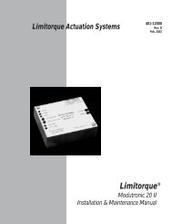
B a u r e i h e N KT e c h n i s c h e D at e n · T E C H N I C A L D ATA · C A R A C T É R I S T I Q U E S T E C H N I Q U E SA b m e s s u n g e nD I M E N S I O N SD I M E N S I O N Sposition indicatorindication de position12
B a u r e i h e N KBaureiheSeriesGammeStellzeit Drehmoment Leistungsaufnahme Dreh- undSchwenkbereichFloating timeTemps de réglages/90°TorqueCouple de rotationNmPower consumptionPuissance absorbéeVATurning rangeValeur de l’angle de rotationGewichtWeightPoidskgNK 1510 15 (13) 10 max. 7 Bis 300° 2,5NK 3010 30 (25) 10 max. 6 Bis 300° 2,5NK 6010 60 (50) 10 max. 6 Bis 300° 2,5NK 3015 30 (25) 15 max. 7 Bis 300° 2,5NK 6015 60 (50) 15 max. 7 Bis 300° 2,5Sonderausführungen mit 3(2,5)s/90°, 4Nm und 6(5)s/90°, 10Nm bei Stückzahlen auf Anfrage.Special versions with 3(2.5)s/90°, 4Nm and 6(5)s/90°, 10Nm for production batches on request.Versions spéciales avec 3(2,5)s/90°, 4Nm et 6(5)s/90°, 10Nm en cas de nombres de pièce sur demande.13
B a u r e i h e N KZ u b e h ö r · A C C E S S O R I E S · A C C E S S O I R E S1 2 3Weghilfsschaltern Bis zu vier zusätzliche Schalter möglichn Alle Schalteranschlüsseauf Klemmen geführtn Stellwinkel können stufenloseingestellt werdenn Auch als Nachrüstbausatz lieferbarSchalterartEin Umschalter (Öffner/Schließer)Kontakte: Silber; zwangstrennend (Option)Schaltstrom: max. 6ASchaltspannung: 250VMech. Lebensdauer: max. 15 x 10 6(Anzahl Schaltbetätigungen)Potentiometern In verschiedenen Ausführungenn Zur Stellungsrückmeldungn Sonderpotentiometer auf Anfrage,z. B. für elektronische Brennstoff-/Luft-VerbundregelungAUXILIARY PATH SWITCHESn Up to four additional switchesn All switch connections wiredto terminalsn Regulating angle infinitely adjustablen Also available as retrofitting setSwitch typeOne change-over switch(normally closed/normally open)Contacts: silver;forced separation (optional)Switching current: max. 6ASwitching voltage: 250VMechanical life: max. 15 x 10 6(number of switching operations)POTENTIOMETERSn In various designsn For position response synchron Special potentiometers on request,e.g. for electronic fuel/air coupledcontrolINTERRUPTEURSAUXILIAIRES DE PARCOURS1 1 122n Jusqu’à quatre interrupteurs auxiliairessupplémentaires sont possiblesn Toutes les connexions d’interrupteursont guidées sur une barrette à bornesn Les angles de réglage peuvent êtreréglés en continun Egalement disponible en tant que complémentd’équipementType d’interrupteurUn inverseur (contact de repos/travail)Contacts : Argent; sectionneur forcé(en option)Courant de commutation: 6A maximumTension de commutation: 250VDurée de vie méc. : 15 x 10 6 max.(par nombre de commutations)POTENTIOMÈTRESn En différentes versionsn Pour la répétition de positionn Potentiomètres spéciaux sur demande,par ex. pour le réglage combiné électriquedes combustibles et de l’air214
B a u r e i h e N K4 56StromausgangCURRENT OUTPUTSORTIE DE COURANT3 3 3n Stellungsrückmeldung 4-20mAn Position response synchro 4-20 mAn Répétition de position 4-20mAServiceschalterFür manuelles Verfahren des Antriebesn Hand-/Automatik-Betriebn Links-/Rechtslaufn Im oder am Antrieb integriertBesteht aus den Schaltern für:n Hand-/Automatik-Betrieb (Kippschalter)n Links-/Rechtslauf (Tastschalter)Stellungsanzeigen Mechanischn Einstellbarn In AntriebshaubeMIKROPROZESSOR-REGLEr PMR-NKn Eingang 4-20mAn Ausgang 4-20mAn Wirkrichtungsumkehrn Stromversorgung 230V, 50(60)HzSERVICE SWITCHESFor manual traversing of actuatorn Manual-/automatic operationn Anticlockwise/clockwise rotationn Incorporated in or on actuatorConsists of the switches for:n Manual-/automatic operation(toggle switch)n Anticlockwise/clockwise rotation(push-button)POSITION INDICATORn Mechanicaln Adjustablen In actuator hoodMICROPROCESSORCONTROLLER PMR-NKn Input 4-20mAn Output 4-20mAn Inversion of the directionn Power supply 230V, 50(60)HzCOMMUTATEURSDE SERVICE4 4 45656Pour l’actionnement manueldu servomoteurn Fonctionnement manuel/automatiquen Rotation à gauche/Rotation à droiten Intégrés au servomoteur ou placéesdessusComprenant les interrupteurs pour:n Le fonctionnement manuel/automatique(interrupteur à bascule)n La rotation à gauche/rotation à droite(poussoir)INDICATION DE POSITIONn Mécaniquen Réglablen A l’intérieur du capotREGULATEUR A MICRO-PROCESSEUR PMR-NKn Entrée 4-20mAn Sortie 4-20mAn Inversion de la direction de rotationn Alimentation en courant 230V,50(60)Hz5615
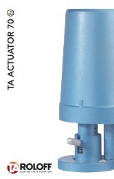
B a u r e i h e N LARIS Dreh- und Schwenkantriebe werdenüberwiegend zum Bewegen, Regelnund Steuern von industriellen Armatureneingesetzt. Betätigt werden z. B. RegelundDrosselklappen, die ARIS auch alsKomplett-Armaturensysteme anbietet.Der kostengünstig in Serie gefertigteStellantrieb mit einer Einschaltdauer von100% ist in vier Ausführungen ab Lagerlieferbar, entweder als Standard-Antrieboder als Regelantrieb für die Ansteuerungmit 4-20mA, in Verbindung mit demARIS Mikroprozessorregler PMR 2-LC.ARIS rotary and part-turn valve actuatorsare primarily used to move, regulateand control industrial valves such ascontrol and butterfly valves, which ARISalso offers as a complete valve system.The actuator is economically produced inseries and is rated at 100% continuousduty. It is available ex stock in four versions,either as a standard actuator or as avariable speed actuator for control signal4-20mA, in combination with ARIS microprocessorcontroller PMR 2-LC.Les actionneurs rotatifs et à fraction detour ARIS sont surtout utilisés à des finsd’actionnement, de réglage et de commandedes robinetteries industrielles. Ilsservent par exemple à actionner des clapetsrégulateurs et d’étranglement quisont également proposés par ARIS commeun système de robinetterie complet.Ce servomoteur d’un prix avantageux estfabriqué en série et se caractérise par unedurée de mise en circuit de 100%. Il estproposé en quatre versions par l’usine;soit comme servomoteur standard oucomme régulateur pour la commandeavec 4-20mA en combinaison avec lerégulateur à microprocesseur ARIS PMR2-LC.16
B a u r e i h e N Ll a g e r p r o g r a m mS T O C K R A N G EP R O G R A M M E S E N S T O C Kn Kompakte Bauform insolider Industrieausführungn Robust und wartungsfrein KurzschlussfesterSynchronmotorn Beliebige Einbaulagen Keine mechanischeBremse erforderlichn Absolute Regelgenauigkeitdurch extrem kurze StartundStoppzeiten des Motors(Millisekunden)n Konstante Stellzeitenauch bei Spannungs- undBelastungsschwankungenn Kostengünstign Lagerprogramm mitkurzen Lieferzeitenn Zahlreiche Optionenwie zusätzliche Schalter,Potentiometer, MikroprozessorreglerPMR 2-LC,Ex-Zone 2 und 22n Compact design in sturdyindustrial qualityn Robust and maintenance-freen Short circuit-proofsynchronous motorn Suitable for any fitting positionn No mechanical brake requiredn Absolute control accuracythrough extremely short motorstarting and stopping times(Milliseconds)n Constant control times,even under voltage and loadfluctuationsn Cost-effectiven Stock range withshort delivery timesn Many optional extras such asadditional switches,potentiometers, microprocessorcontroller PMR 2-LC,explosion zones 2 and 22n Forme de construction compacteen version industrielle soliden Robuste et sans entretienn Moteur synchrone protégé contreles courts-circuitsn Position de montage au choixn Aucun frein mécanique nécessairen Précision de réglage absoluegrâce aux temps de mise enmarche et d’arrêt du moteurextrêmement courts(millisecondes)n Temps de réglage constantsmême en cas de fluctuations detension et de chargen Prix avantageuxn Programmes en stock avec decourts délais de livraisonn Nombreuses options tellesqu’interrupteurs supplémentaires,potentiomètres et régulateursà microprocesseur PMR 2-LC,zones 2 et 22 antidéflagrantes.17
B a u r e i h e N LP r o d u k ta n g a b e n · P R O D U C T D ATA · C A R A C T É R I S T I Q U E S D E P R O D U I TGehäusen Gehäuse aus Zinkdruckgussn Haube aus korrosionsbeständigemAluminiumdruckguss, lackiert mitsilikonfreiem Strukturlackn 1 Kabelverschraubung,2 Kabeleinführungenn Schutzart IP65 nach DIN EN 60529Motorn Kurzschlussfester Wechselstrom-Synchronmotorn Einpolig-reversierbarn 230V ±10%, 50/60Hz ±5%n 100% ED (Einschaltdauer)n Start- und Stoppzeitenim Millisekundenbereichn Regelschritte werden genau eingehaltenn Isolationsklasse B nach VDE 0530Getrieben Robustes, wartungsfreiesStirnradgetriebe aus Stahln Dauerfettschmierungn Selbstschmierendes SpezialbronzelagerAnsteuerungn Auf-/Zu-Signaln Option:– ARIS MikroprozessorreglerPMR 2-LC (im Antrieb integriert) fürSollwerte 0/4-20mA, 0-10VUmgebungstemperaturn -15°C bis +60°CWegabschaltungn Zwei Wegendschaltern Betätigung aller wegabhängigenSchalter erfolgt über von Handeinstellbare Schaltnockenn Exakte Begrenzung der EndlagenHOUSINGn Zinc diecasting housingn Hood made from corrosion-resistantaluminium diecasting painted withsilicone-free texture paintn 1 cable fitting,2 cable entriesn Protection class IP65 to DIN EN 60529Motorn Short circuit-proof alternating currentsynchronous motorn Single pole, reversiblen 230V ±10%, 50/60Hz ±5%n 100% continuous dutyn Starting and stopping timesin millisecond rangen Control steps are maintained 100%n Insulation category B to VDE 0530GEARBOXn Robust, maintenance-freesteel spur gearingn Permanently grease lubricatedn Self-lubricating special bronze bearingsACTIVATIONn Open/close signaln Option:– ARIS microprocessor PMR 2-LC(incorporated in actuator) for desiredvalue 0/4-20mA, 0-10VAMBIENT TEMPERATUREn -15°C to +60°CPOSITION SWITCH-OFFn Two limit switchesn All path-dependent switches operatedvia manually adjustable camsn Exact limitation of end of travelBOÎTIERn Boîtier en zinc moulé sous pressionn Capot en aluminium moulé sous pressionrésistant à la corrosion, laqué enlaque structurée sans siliconen 1 passe-câble à vis, 2 entrées de câblen Classe de protection IP65 selon DINEN 60529MOTEURn Moteur synchrone à courant alternatifprotégé contre les courts-circuitsn Unipolaire à marche réversiblen 230V ±10%, 50/60Hz ±5%.n Durée de mise en circuit de 100%n Temps de mise en marche et d’arrêt dequelques millisecondesn Les pas de réglage sont scrupuleusementrespectésn Classe d’isolement B selon VDE 0530ENGRENAGEn Réducteur à engrenage droit en aciersolide et sans entretienn Graissage permanentn Coussinets spéciaux en bronzeautolubrifiantsCOMMANDEn Signal Ouvert/Fermén Option:– Régulateur à microprocesseur ARISPMR 2-LC (intégré au servomoteur)pour les valeurs de consigne 0/4- 20mA, 0-10VTEMPÉRATURE AMBIANTEn -15°C jusqu’à +60°CARRÊT DE PARCOURSn Deux interrupteurs de fin de coursen L’actionnement de tous les interrupteursdépendants du parcours est effectuémanuellement par des cames decontacteur réglables.n Limitation exacte des positions de fin decourse18
B a u r e i h e N lOptionenn Zulassung für Ex-Zone 2 und 22n Sonderspannungen auf Anfragen Handrad / Stellungsanzeigen Vielfältiges Zubehör (s. Seite 22)Montagen Einfache Montage durch stabileWinkelkonsole/ISO-Konsolen Problemlose Verbindung zurArmaturenwelle durch:– Handhebelkupplung– Hebelarm, Klemmhebelarm,Kugelgelenk, Gestänge, Federgestänge– Elastische Wellenkupplung– Starre Wellenkupplung– KlauenkupplungBestellangabenn Gerätetypn Drehmomentn Stellzeitn Motorspannung und -frequenzn Gewünschte Optionenn Bei Bestellung mit Potentiometer wirdder elektrische Drehwinkel standardmäßigauf 90° Stellweg aufgelöstn Auflösung auf anderenStellweg möglichn Auf Wunsch können die Schalter aufden vorgesehenen Stellweg eingestelltwerdenOPTIONSn Approved for explosion zones 2 and 22n Special voltages on requestn Hand wheel / position indicatorn Large range of accessories (s. page 22)INSTALLATIONn Simple fitting via anglebracket/ISO bracketn Easy connection to valve shaft via:– Hand lever coupling– Lever arm, clamping lever,ball-and-socket joint, rods,spring rods– Flexible shaft coupling– Rigid shaft coupling– Dog clutchORDERING DATAn Modeln Torquen Floating timen Motor voltage and frequencyn Options requiredn If ordered with potentiometers, theelectrical angle of rotation is set to 90°regulating distance as standardn Regulating distance can be set to otheranglesn On request, the switches can be set tothe planned regulating distanceOPTIONSn Homologation pour les zones 2 et 22antidéflagrantesn Tensions spéciales sur demanden Volant à main/ Indication de positionn Large gamme d’accessoires (v. page 22)Montagen Montage facile au moyen d’une consoleà équerre/console ISOn Raccordement aisé à la tige de robinetteriepar :– Accouplement à levier manuel– Bras de levier, bras de levier deserrage, articulation à rotule, tringles,tringles à ressorts– Accouplement de l’arbre élastique– Accouplement de l’arbre rigide– Accouplement à brochesRÉFÉRENCES À RAPPELERPOUR LA COMMANDEn Type d’appareiln Couple de rotationn Temps de réglagen Tension et fréquence du moteurn Options désiréesn En cas de commande avec potentiomètre,l’angle de rotation électriqueest résolu en version standard sur leparcours de réglage 90°n Possibilité d’adaptation à un autreparcours de réglagen Sur demande, les interrupteurs peuventêtre réglés au parcours de réglage prévu19
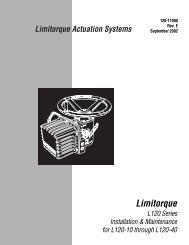
B a u r e i h e N LT e c h n i s c h e D at e n · T E C H N I C A L D ATA · C A R A C T É R I S T I Q U E S T E C H N I Q U E SA b m e s s u n g e nD I M E N S I O N SD I M E N S I O N SGetriebeausrastunggear disengagementdébrayage du réducteurHandradhand wheelvolant à main(deep)Option Passfedernutoutput shaft with feather keyarbre de sortie avec ressort d’ajustage20Option ISO-FlanschISO flangebride ISO
B a u r e i h e N lBaureiheSeriesGammeStellzeit Drehmoment Leistungsaufnahme Dreh- undSchwenkbereichFloating timeTemps de réglages/90°TorqueCouple de rotationNmPower consumptionPuissance absorbéeVATurning rangeValeur de l’angle de rotationGewichtoptional bis 10UNL 1520 15 20 max. 20 Standard 0-90°, optionally up to 10U 3,4jusqu`à 10U en optionoptional bis 10UNL 3020 30 20 max. 20 Standard 0-90°, optionally up to 10U 3,4jusqu`à 10U en optionoptional bis 10UNL 3040 30 40 max. 20 Standard 0-90°, optionally up to 10U 3,4jusqu`à 10U en optionoptional bis 10UNL 6020 60 20 max. 20 Standard 0-90°, optionally up to 10U 3,4jusqu`à 10U en optionoptional bis 10UNL 6040 60 40 max. 20 Standard 0-90°, optionally up to 10Ujusqu`à 10U en option3,4WeightPoidskgSonderwellen auf Anfrage.Special shafts on request.Arbres spéciaux sur demande.21
B a u r e i h e N LZ u b e h ö r · A C C E S S O R I E S · A C C E S S O I R E S1 2 3Weghilfsschaltern Bis zu zwei zusätzliche Schaltermöglichn Alle Schalteranschlüsseauf Klemmen geführtn Stellwinkel können stufenloseingestellt werdenn Auch als Nachrüstbausatz lieferbarSchalterartEin Umschalter (Öffner/Schließer)Kontakte: Silber, zwangstrennend (Option)Schaltstrom: max. 6ASchaltspannung: 250VMech. Lebensdauer: max. 15 x 10 6(Anzahl Schaltbetätigungen)Potentiometern In verschiedenen Ausführungenn Zur Stellungsrückmeldungn Sonderpotentiometer auf Anfrage,z. B. für elektronische Brennstoff-/Luft-VerbundregelungStromausgangn Stellungsrückmeldung 4-20mASTELLUNGSANZEIGEn Mechanischn Einstellbarn In AntriebshaubeAUXILIARY PATH SWITCHESn Up to two additional switchesn All switch connections wiredto terminalsn Regulating angle infinitely adjustablen Available as retrofitting setSwitch typeOne change-over switch(normally closed/normally open)Contacts: silver;forced separation (optional)Switching current: max. 6ASwitching voltage: 250VMechanical life: max. 15 x 10 6(number of switching operations)POTENTIOMETERSn In various designsn For position response synchron Special potentiometers on request,e.g. for electronic fuel/air coupledcontrolCURRENT OUTPUTn Position response synchro 4-20mAPOSITION INDICATORn Mechanicaln Adjustablen In actuator hoodINTERRUPTEURSAUXILIARES DE PARCOURS1 1 12 23 34 4n Jusqu’à deux interrupteurs auxiliairessupplémentaires sont possiblesn Toutes les connexions d’interrupteursont guidées sur une barrette à bornesn Les angles de réglage peuvent êtreréglés en continun Egalement disponible en tant quecomplément d’équipementType d’interrupteurUn inverseur (contact de repos/travail)Courant de commutation: 6A maximumTension de commutation: 250VDurée de vie méc.: 15 x 10 6 max.(par nombre de commutations)POTENTIOMÈTRESn En différentes versionsn Pour la répétition de positionn Potentiomètres spéciaux sur demande,par ex. pour le réglage électronique descombustibles et de l’air.SORTIE DE COURANTn Répétition de position 4-20mAINDICATION DE POSITIONn Mécaniquen Réglablen A l’intérieur du capot23422
B a u r e i h e N l45 6MikroprozessorreglerPMR 2-LCMICROPROCESSOR-CONTROLLER PMR 2-LCRÉGULATEUR AMICROPROCESSEUR PMR 2-LC5 5 5Der ARIS Mikroprozessorregler PMR 2-LCwird zum einfachen und genauen Positionierendes ARIS Stellantriebes NL eingesetzt.Die Ansteuerung erfolgt über eineexterne Sollwertvorgabe mit Normsignalen.Durch die vielfältigen Ansteuerungsmöglichkeitenund die sehr einfachen Einstellungenwird der Mikroprozessorregler innahezu allen Industriebereichen eingesetzt,wo eine exakte Positionierung von Stellantriebenverlangt wird.Besonderheitenn Einfache Bedienungn Einstellung ohne Sollwertvorgabemöglich (Standard-Einstellungen sindvoreingestellt)n Kurze Inbetriebnahmezeitn Keine Relais, Triacs zur Motorsteuerungn Eingang und Ausgang galvanischgetrenntn Zwei integrierte EndlagenschalterTechnische Datenn Eingang: 4-20mA / 0-20mA /0-5V / 0-10Vn Ausgang: 4-20mA / 0-20mAn Auflösung: 10Bitn Umgebungstemperatur: 0° bis +60°Cn Stromversorgung: 230V 50(60)HzServiceschalterFür manuelles Verfahren des Antriebsn Hand-/Automatik-Betriebn Links-/Rechtslaufn Im oder am Antrieb integriertBesteht aus den Schaltern für:n Hand-/Automatik-Betrieb (Kippschalter)n Links-/Rechtslauf (Tastschalter)6The ARIS microprocessor controllerPMR 2-LC is used for easy and accuratepositioning of ARIS NL actuators.Activation is via an external set value witha standard signal. A large number of controloptions and very simple adjustmentsenable the microprocessor controller to beused in practically any industrial applicationwhere accurate positioning via actuatorsis called for.Special featuresn Simple operationn Setting up possible without prescribedset value(standard settings are preset)n Short commissioning periodn No relays – motor control via triacsn Input and output electrically separatedn Two integrated limit switchesTechnical datan Input: 4-20mA / 0-20mA / 0-5V /0-10Vn Output: 4-20mA / 0-20mAn Resolution: 10Bitn Ambient temperature: 0° to +60°Cn Power supply: 230V 50(60)HzSERVICE SWITCHESFor manual movement of actuatorn Manual-/automatic operationn Anticlockwise/clockwise rotationn Incorporated in or on actuatorConsists of the switches for:n Manual-/automatic operation(toggle switch)n Anticlockwise/clockwise rotation(push-button)6Le régulateur à microprocesseur ARISPMR 2-LC permet le positionnement facileet précis du servomoteur ARIS NL. Lacommande se fait par un réglage externe dela valeur de consigne au moyen des signauxstandard. Grâce aux nombreuses possibilitésde commande et à la grande facilité deréglage, le régulateur à microprocesseurest utilisé dans presque tous les domainesindustriels pour lesquels un positionnementexact des servomoteurs est indispensable.Particularitésn Maniement simplen Réglage possible sans prédéfinition dela valeur de consigne (réglages standardpar l’usine)n Mise en service rapiden Aucun relais, commande du moteur partriacsn Isolement électrique de l’entrée et de lasortien Deux interrupteurs de fin de courseintégrésCaractéristiques techniquesn Entrée: 4-20mA / 0-20mA / 0-5V / 0-10Vn Sortie: 4-20mA / 0-20mAn Résolution: 10 bitsn Température ambiante: 0° bis +60°Cn Alimentation en courant: 230V50(60)HzCOMMUTATEUR DE SERVICEPour l’actionnement manuel du servomoteurn Fonctionnement manuel/automatiquen Rotation à gauche/à droiten Intégré au servomoteur ou placé dessusComprenant les interrupteurs pour :n Le fonctionnement manuel/automatique(interrupteur à bascule)n La rotation à gauche/rotation à droite(poussoir)623
a u r e i h e nN / K-A / K / vARIS Stellantriebe werden überwiegendzum Bewegen, Regeln und Steuern vonindustriellen Armaturen eingesetzt. Betätigtwerden z.B. Regel- und Drosselklappen,Absperrklappen, Ventile undSchieber; aber auch Dosierpumpen,Druckregler, Regelgetriebe usw.Zur Produktpalette gehören die Dreh- undSchwenkantriebe der Baureihe N sowiefolgende Linearantriebe: die Schubantriebeder Baureihe K-A, die Klappenverstellerder Baureihe K und die Ventilantriebeder Baureihe V.ARIS actuators are primarily used tomove, regulate and control industrialvalves such as control and regulatingvalves, butterfly valves and slide valves,and also metering pumps, pressure regulators,control gears etc.The product range includes rotary andpart-turn actuators of series N and thefollowing linear motion actuators: linearactuators series K-A, flap regulators seriesK and valve actuators series V.Les servomoteurs rotatifs ARIS sontsurtout utilisés pour l’actionnement, leréglage et la commande de robinetteriesindustrielles. Ils servent par exempleà actionner des clapets régulateurs etd‘étranglement, des clapets d‘arrêt,des soupapes et vannes, mais aussi despompes de dosage, régulateurs de pression,commandes à réglage etc.Notre éventail de produits comprend lesservomoteurs rotatifs et à fraction de tourde la gamme N ainsi que les servomoteurslinéaires suivants: les servomoteurslinéaires de la gamme K-A, les actionneursde volet de la gamme K et les actionneursde soupape de la gamme V.24
a u r e i h e nN / K-A / K / vE L E K T R I S C H E S T E L L A N T R I E B EU N D Z U B E H Ö RE L E C T R I C A C T U A T O R SA N D A C C E S S O R I E SS E R V O M O T E U R S É L E C T R I Q U E SE T A C C E S S O I R E S25
B a u r e i h e NARIS Dreh- und Schwenkantriebekönnen entweder in festgelegten Nennschwenkwinkelnoder in komplettenUmdrehungen eine Vielzahl von unterschiedlichenArmaturen betätigen.Die kompakten und robusten Antriebesind auch für hohe Umgebungstemperaturengeeignet.Durch zahlreiche Optionen sind die ARISDreh- und Schwenkantriebe flexibel infast jeder Umgebung und Anwendungeinsetzbar.ARIS rotary and part-turn actuators canbe used to operate a variety of differentvalves, either over a specified nominalpivoting angle or with a complete revolution.These compact, robust actuatorsare suitable for high ambient temperatures.A large number of options enable ARISrotary and part-turn actuators to be flexiblyused in practically any application andenvironment.Les servomoteurs rotatifs et à fractionde tour ARIS peuvent actionner unemultitude de robinetteries diverses, soitdans des angles de rotation nominauxprédéfinis, soit dans des rotations complètes.Ces servomoteurs compacts etrobustes conviennent également à destempératures ambiantes élevées.Grâce à leurs nombreuses options, lesservomoteurs rotatifs et à fraction de tourARIS conviennent à une utilisation flexibledans presque tous les environnementset pour presque toutes les applications.26
B a u r e i h e ND R E H - U N D S C H W E N K A N T R I E B ER O TA R Y A N D PA R T-T U R N A C T U AT O R SS E R V O M O T E U R S R O TAT I F SE T A F R A C T I O N D E T O U Rn Kompakte Bauform insolider Industrieausführungn Robust und wartungsfrein KurzschlussfesterSynchronmotorn Beliebige Einbaulagen Keine mechanischeBremse erforderlichn Absolute Regelgenauigkeitdurch extrem kurze StartundStoppzeiten des Motors(Millisekunden)n Konstante Stellzeitenauch bei Spannungs- undBelastungsschwankungenn Absoluter Gleichlauf bei parallelbetriebenen Antriebenn Kostengünstign Zahlreiche Optionen wie zusätzlicheSchalter, Potentiometer,Stellungsmelder, Mikroprozessorregler,ProfibusDP, Ex-Zone 2 und 22,CAN-OPEN und anderen Compact design in sturdyindustrial qualityn Robust and maintenance-freen Short circuit-proofsynchronous motorn Suitable for any fitting positionn No mechanical brake requiredn Absolute control accuracythrough extremely short motorstarting and stopping times(Milliseconds)n Constant control times,even under voltage and loadfluctuationsn 100% synchronized whentwo actuators operate inparalleln Cost-effectiven Many optional extras such asadditional switches, potentiometers,position indicators,microprocessor controllers,Profibus DP, explosion zones2 and 22, CAN-OPEN andothersn Forme de construction compacteen version industrielle soliden Robuste et sans entretienn Moteur synchrone protégé contreles courts-circuitsn Position de montage au choixn Aucun frein mécanique nécessairen Précision de réglage absoluegrâce aux temps de mise enmarche et d’arrêt du moteurextrêmement courtsn Temps de réglage constantsmême en cas de fluctuations detension et de chargen Synchronisme absolu dans lecas de servomoteurs en exploitationparallèlen Prix avantageuxn Nombreuses options tellesqu’interrupteurs supplémentaires,potentiomètres, indicateursde position, régulateurs àmicroprocesseur, Profibus DP,zones 2 et 22 antidéflagrantes,CAN-OPEN et autres27
B a u r e i h e NP r o d u k ta n g a b e n · P R O D U C T D ATA · C A R A C T É R I S T I Q U E S D E P R O D U I TGehäusen Gehäuse aus Zinkdruckgussn Haube aus korrosionsbeständigemAluminiumdruckguss, lackiert mitsilikonfreiem Strukturlackn Die Haube kann bei Bedarf durchDistanzrahmen erhöht werdenn Drei Kabeleinführungen M20 x 1,5n Schutzart IP54 nach DIN EN 60529n Optionen:– Schutzart IP65/IP66/IP67– Dauerheizung zur Verhinderungvon KondenswasserbildungMotorn Kurzschlussfester Wechselstrom-Synchronmotorn Einpolig-reversierbarn 230V ±10%, 50/60Hz ±5%.n 100% ED (Einschaltdauer)n Start- und Stoppzeitenim Millisekundenbereichn Regelschritte werden genau eingehaltenn Isolationsklasse B nach VDE 0530n Optionen:– Drehstrommotor– Gleichstrommotor– Sonderspannungen– Sonderfrequenzen– TemperaturfühlergrenzmomentMotor(optionen)n Konstantes Drehmoment im Blockierfalldurch Hysterese-Magnetkupplungn Kraftfluss wird bei Erreichen desGrenzmomentes durch Hysterese-Magnetkupplung unterbrochenn Elektrische Versorgung muss beiErreichen des Grenzmomentes nichtabgeschaltet werdenHOUSINGn Zinc diecasting housingn Hood made from corrosion-resistantaluminium diecasting painted withsilicone-free texture paintn The hood can be extended via a spacerframe if requiredn 3 cable entries M20 x 1.5n Protection class IP54 to DIN EN 60529n Options:– Protection class IP65/IP66/IP67– Constant heating to preventcondensation of waterMotorn Short circuit-proof alternating currentsynchronous motorn Single pole, reversiblen 230V ±10%, 50/60Hz ±5%n 100% continuous dutyn Starting and stopping timesin millisecond rangen Control steps are maintained 100%n Insulation category B to VDE 0530n Options:– Three-phase motor– Direct current motor– Special voltages– Special frequencies– Temperature sensorTORQUE LIMIT MOTOR(OPTIONAL)n Constant torque via hysteresis magneticcoupling if locking occursn Power flow interrupted by hysteresismagnetic coupling when torque limit isreachedn Power supply does not need to be switchedoff when torque limit is reachedBOÎTIERn Boîtier en zinc moulé sous pressionn Capot en aluminium moulé sous pressionrésistant à la corrosion, laqué enlaque structurée sans siliconen En cas de besoin, le capot peut êtrerehaussé au moyen d’un châssisd’écartementn Trois entrées de câble M20 x 1,5n Classe de protection IP54 selon DINEN 60529n En option :– Classe de protection IP65/IP66/IP67– Chauffage permanent pour éviter lescondensations d’eauMOTEURn Moteur synchrone à courant alternatifprotégé contre les courts-circuitsn Unipolaire à marche réversiblen 230V ±10%, 50/60Hz ±5%n Durée de mise en circuit de 100%n Temps de mise en marche et d’arrêt dequelques millisecondesn Les pas de réglage sont scrupuleusementrespectésn Classe d’isolement B selon VDE 0530(normes des électrotechniciens allemands)n En option:– Moteur à courant alternatif triphasé– Moteur à courant continu– Tensions spéciales– Fréquences spéciales– Sonde de températureMOTEUR À COUPLE LIMITÉ(EN OPTION)n Couple constant en cas de blocage paraccouplement magnétique à hystérésisn Le flux de force est interrompu parl’accouplement magnétique à hystérésislorsque le couple limité est atteintn L’alimentation en courant ne doit pasêtre coupée lorsque le couple limité estatteint28
B a u r e i h e NGetrieben Robustes, wartungsfreiesStirnradgetriebe aus Stahln Dauerfettschmierungn Selbstschmierende Spezialbronzelagerelektrischer anschlussn Basisplatine als Anschlussplatinemit Printklemmenn Zwei Steckplätze zur Erweiterungmit Potentiometern, zusätzlichenSchaltern u.a.n Problemlose Erweiterung durchzusätzliche AnschlussplatinenAnsteuerungn Auf-/Zu-Signaln Optionen:– ARIS Mikroprozessorregler PMR(im Antrieb integriert) für Sollwerte0/4-20mA, 0-10V oderPotentiometer 1-10kΩ– Profibus DP– CAN-OPENUmgebungstemperaturn -15°C bis +60°Cn Optionen:– Bis +80°C, ED-S3-50%– Bis -40°Cabschaltungn Alle Schalter sind Umschalter mitSilberkontaktenn Schalteranschlüsse auf Klemmleistegeführtn Schaltleistung der Umschalter:Max. 12(6)A, 250V ACn Option:– Schalter mit Goldkontakten oderzwangstrennendGEARBOXn Robust, maintenance-free steel spurgearingn Permanently grease lubricatedn Self-lubricating special bronze bearingsELECTRICAL CONNECTIONn Base PCB as connecting board withprinted terminalsn Two expansion slots for extension withpotentiometers, additional switches, etc.n Easy extension via additionalconnecting boardsACTIVATIONn Open/close signaln Options:– ARIS microprocessor PMR(incorporated in actuator) for setvalue 0/4-20mA, 0-10V orpotentiometer 1-10kΩ– Profibus DP– CAN-OPENAMBIENT TEMPERATUREn -15°C to +60°Cn Options:– Up to +80°C, duty cycle S3-50%– Down to -40°CSWITCHING-OFFn All switches are changeover switcheswith silver contactsn Switch connections on terminal stripn Breaking capacity of changeoverswitch: max. 12(6)A, 250V ACn Option:– Switch with gold contacts or forcedseparationENGRENAGEn Réducteur à engrenage droit en aciersolide et sans entretienn Graissage permanentn Coussinets spéciaux en bronze autolubrifiantsRACCORDEMENT ÉLECTRIQUEn Platine de base en tant que platine deraccordement avec bornes à circuitsimprimésn Deux slots pour une extension avecpotentiomètres, interrupteurs supplémentairesetc.n Extension facile grâce à des platines deraccordement supplémentairesCOMMANDEn Signal Ouvert/Fermén Option:– Régulateur à microprocesseur ARISPMR (intégré au servomoteur) pourles valeurs de consigne 0/4-20mA,0-10V ou potentiomètre 1-10kΩ– Profibus DP– CAN-OPENTEMPÉRATURE AMBIANTEn -15°C jusqu’à +60°Cn En option:– Jusqu’à + 80°C, ED-S3-50%– Jusqu’à -40°CMISE A L’ARRÊTn Tous les interrupteurs sont des inverseursà contacts argentésn Les connexions des interrupteurs sontguidées sur une barrette à bornesn Puissance de coupure des inverseurs:12(6)A, 250V AC max.n En option:– Interrupteurs à contacts dorés ou àséparation forcée29
B a u r e i h e NP r o d u k ta n g a b e n · P R O D U C T D ATA · C A R A C T É R I S T I Q U E S D E P R O D U I Twegabschaltungn Zwei Wegendschalter (Standard)n Betätigung aller wegabhängigenSchalter erfolgt über stufenlos einstellbareSchaltnocken (siehe Seite 76)n Exakte Begrenzung der Endlagen undZwischenstellungenn Wegendschalter mit Umschaltkontaktenfür externe Meldungen oderFolgesteuerungenpotentiometer (option)n Zur externen Stellungsanzeigen Der elektrische Drehwinkel des Potentiometerskann auf den kundenseitiggewünschten Stellweg aufgelöst werden(Standard 90°)n Es können bis zu drei Potentiometereingebaut werdenn Wahlweise, je nach Anwendung, alsDraht-, Leitplast- oder MehrwendelpotentiometerOptionenn Abweichende Spannung/Frequenzn Abweichende Umgebungstemperaturn Höhere Schutzartn Handrad/Getriebeauskupplungn Zusätzliche Weghilfsschaltern Sonderschaltnockenn Mikroprozessorregler PMRn Stellungsmeldern Heizungn Relaisn Stellungsanzeigen Potentiometern Bauteile nach UL-Normelektrischer anschlussn Gemäß Anschlussplann Schutzmaßnahmen nach VDEund EVU sind einzuhaltenn Optionen:– Zusatzeinrichtung für denParallelbetrieb mehrerer Stellantriebe– Sonderspannungen/-frequenzen– Relais (im Antrieb integriert) fürverschiedene FunktionenPOSITION SWITCH-OFFn Two limit switches as standardn All path-dependent switches operatedvia infinitely adjustable control cams(see page 76)n Exact limitation of end of travel andintermediate positionsn Limit switches with changeover contactsfor external signals or automaticsequence controlPOTENTIOMETERS (OPTIONAL)n For external position indicatorsn The electrical angle of rotation of thepotentiometer can be set to the regulatingdistance requested by the customer(standard 90°)n Up to three potentiometers can be fittedn According to application as wirewound,electrically conducting plasticwoundor multiple helix potentiometerto choiceOPTIONSn Other voltages/frequenciesn Other ambient temperaturesn Higher protection classn Hand wheel / gear disengagementn Additional auxiliary path switchesn Special control camsn PMR microprocessor controllern Position indicatorn Heatingn Relaysn Position indicationn Potentiometersn Components to UL StandardELECTRICAL CONNECTIONn See connection drawingn Protective measures to VDE und EVUmust be complied withn Options:– Additional equipment for runningseveral actuators in parallel– Special voltages /-frequencies– Relays for different functions(incorporated in actuator)ARRÊT DE PARCOURSn Deux interrupteurs de fin de course(standard)n L’actionnement de tous les interrupteursdépendants du parcours est effectuépar des cames de contacteur réglablesen continu (voir page 76)n Limitation exacte des positions de fin decourse et des positions intermédiairesn Interrupteurs de fin de course avec contactsinverseurs pour messages externesou contrôle automatique à séquencePOTENTIOMÈTRES (EN OPTION)n Pour l’indication de position externen L’angle de rotation électrique du potentiomètrepeut être résolu sur le parcoursde réglage souhaité par le client(standard 90°)n Jusqu’à 3 potentiomètres peuvent êtremontésn Au choix en fonction de l’applicationcomme potentiomètre bobiné, multihélicoïdalou à plastique conducteurOPTIONSn Tension/Fréquence divergenten Température ambiante divergenten Classe de protection supérieuren Volant de commande pour réglage manuel/Dispositifde débrayage du réducteurn Interrupteurs auxiliaires de parcourssupplémentairesn Cames de contacteur spécialesn Régulateur à microprocesseur PMRn Indicateur de positionn Chauffagen Relaisn Indication de positionn Potentiomètren Composants selon la norme ULRACCORDEMENT ELECTRIQUEn Suivant le plan de couplagen Les mesures de protection selon VDE etEVU doivent être respectéesn En option :– Equipement supplémentaire pourl’exploitation en parallèle de plusieursservomoteurs– Tensions et fréquences spéciales– Relais (intégré au servomoteur) pourdifférentes fonctions30
B a u r e i h e NMontagen Einfache Montage durch stabileWinkelkonsole/ISO-Konsolen Problemlose Verbindung zurArmaturenwelle durch:– Handhebelkupplung– Hebelarm, Klemmhebelarm,Kugelgelenk, Gestänge, Federgestänge– Elastische Wellenkupplung– Starre Wellenkupplung– KlauenkupplungHandverstellung (option)n Für die manuelle Verstellung derAbtriebswelle/Armatur mittels Handradoder Getriebeauskupplungn Während der Handverstellung bleibenalle justierten Schaltnocken- undPotentiometereinstellungen erhaltenn Handrad dreht bei elektrischerBetätigung nicht mitBestellangabenn Gerätetypn Drehmomentn Stellzeitn Motorspannung/-frequenzn Gewünschte Optionenn Spannungen für elektrischesZubehör (falls abweichend vonder Motorspannung)n Bei Bestellung mit Potentiometer wirdder elektrische Drehwinkelstandardmäßig auf 90° Stellwegaufgelöstn Auflösung auf anderenStellweg möglichn Auf Wunsch können die Schalter aufden vorgesehenen Stellweg eingestelltwerdenINSTALLATIONn Simple fitting via angle bracket/ISObracketn Easy connection to valve shaft via:– Hand lever coupling– Lever arm, clamping lever,ball-and-socket joint, rods,spring rods– Flexible shaft coupling– Rigid shaft coupling– Dog clutchMANUAL OPERATION (OPTIONAL)n Either hand wheel or gear disengagementcan be used for manual operationof the output shaftn All control cam and potentiometersettings are maintained during manualoperationn Hand wheel does not rotate duringelectrical actuationORDERING DATAn Modeln Torquen Floating timen Motor voltage and frequencyn Options requiredn Voltages for electrical accessories(if different from the motor voltage)n For order with potentiometers it isstandard practice to set the max.range to 90° regulating distancen May be set to another regulatingdistance if requestedn Switches can be set to the regulatingdistance requiredMontagen Montage simple grâce à une console àéquerre robuste/console ISOn Raccordement aisé à la tige de robinetteriepar:– Accouplement à levier manuel– Bras de levier, bras de levier deserrage, articulation à rotule, tringles,tringles à ressorts– Accouplement de l’arbre élastique– Accouplement de l’arbre rigide– Accouplement à brochesRÉGLAGE MANUEL (EN option)n Pour le réglage manuel de l’arbre desortie / de la robinetterie à l’aide d’unvolant à main ou d’un dispositif dedébrayage du réducteurn Pendant le réglage manuel, tous les réglagesajustés des cames de contacteuret des potentiomètres sont maintenus.n Lors de l’actionnement électrique, levolant à main ne tourne pasRÉFÉRENCES À RAPPELERPOUR LA COMMANDEn Type d’appareiln Couple de rotationn Temps de réglagen Tension et fréquence du moteurn Options souhaitéesn Tensions pour les accessoires électriques(si celles-ci divergent de latension moteur)n En cas de commande avec potentiomètre,l’angle de rotation électriqueest résolu en version standard sur leparcours de réglage 90°n En cas de besoin, résolution possiblesur un autre parcours de réglagen Sur demande, les interrupteurs peuventêtre réglés sur le parcours de réglageprévu31
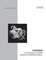
B a u r e i h eN 1 - 4 / N - A ST e c h n i s c h e D at e n · T E C H N I C A L D ATA · C A R A C T É R I S T I Q U E S T E C H N I Q U E SA b m e s s u n g e nD I M E N S I O N SD I M E N S I O N SGetriebeausrastunggear disengagementdébrayage du réducteurVierkantwellesquare shaftarbre carréhand wheelvolant à mainposition indicatorindication de positionTypeTime1all1Minimale Haubenhöhe mit eingebautem PMR 3 H = 148mm.Minimal height of hood with integrated PMR 3 H = 148mm.Hauteur minimal du capot avec PMR 3 intégré H = 148mm.(deep)32Passfedernutoutput shaft with feather keyarbre de sortie avec ressort d’ajustageISO flangebride ISO
B a u r e i h eN 1 - 4 / N - A SBaureiheSeriesGammeStellzeitFloating timeTemps de réglages/90°DrehmomentTorqueCouple de rotationNmDreh- und SchwenkbereichRotary and swivelling rangeValeur de l‘angle de rotationStandard min./max.Standard min./max.Standard min./max.GradSonderausführungSpecial versionVersion spéciale1 U= 360°GewichtWeightPoidskgN 115306012059153010 - 330°10 - 330°10 - 330°10 - 330°100 U100 U100 U100 U3,53,53,53,5N 2153060120711173510 - 330°10 - 330°10 - 330°10 - 330°100 U100 U100 U100 U3,63,63,63,6N 2A615306037132110 - 330°10 - 330°10 - 330°10 - 330°100 U100 U100 U100 U3,63,63,63,6N 2B25456025252510 - 330°10 - 330°10 - 330°100 U100 U100 U3,93,73,7N 36153060120151530354010 - 330°10 - 330°10 - 330°5 - 330°5 - 330°100 U100 U100 U100 U100 U3,93,83,93,73,6N 46122560404040405 - 330°5 - 330°5 - 330°5 - 330°100 U100 U100 U100 U5,04,03,93,9N 4A815256012060606060605 - 330°5 - 330°5 - 330°5 - 330°5 - 330°100 U100 U100 U100 U100 U5,94,03,93,93,8N-AS 101,83,26,39,5123510 - 330°10 - 330°10 - 330°10 - 330°100 U100 U100 U100 U3,63,63,63,6N-AS 111,21,83,26,39,51,52481010 - 330°10 - 330°10 - 330°10 - 330°10 - 330°100 U100 U100 U100 U100 U3,83,83,83,83,8N-AS 120,61,21,83,26,39,51248122010 - 330°10 - 330°10 - 330°10 - 330°10 - 330°10 - 330°100 U100 U100 U100 U100 U100 U3,83,83,83,83,83,8N-AS 130,61,21,83,26,3248162010 - 330°10 - 330°10 - 330°10 - 330°10 - 330°100 U100 U100 U100 U100 U3,93,93,93,93,9N-AS 140,30,450,81,62,4424712182010 - 330°10 - 330°10 - 330°10 - 330°10 - 330°10 - 330°100 U100 U100 U100 U100 U100 U4,84,84,84,84,84,8N-AS 150,150,30,450,81,62,424610182010 - 330°10 - 330°10 - 330°10 - 330°10 - 330°10 - 330°100 U100 U100 U100 U100 U100 U5,75,75,75,75,75,733
B a u r e i h eN 5 - 8T e c h n i s c h e D at e n · T E C H N I C A L D ATA · C A R A C T É R I S T I Q U E S T E C H N I Q U E SA b m e s s u n g e nD I M E N S I O N SD I M E N S I O N SGetriebeausrastunggear disengagementdébrayage du réducteurVierkantwellesquare shaftarbre carréposition indicatorindication de positionhand wheelvolant à mainTypeTime1Minimale Haubenhöhe mit eingebautem PMR 3 H = 148mm.Minimal height of hood with integrated PMR 3 H = 148mm.Hauteur minimal du capot avec PMR 3 intégré H = 148mm.(deep)Passfedernutoutput shaft with feather keyarbre de sortie avec ressort d’ajustageISO flangebride ISO34
B a u r e i h eN 5 - 8BaureiheSeriesGammeStellzeitFloating timeTemps de réglages/90°DrehmomentTorqueCouple de rotationNmDreh- und SchwenkbereichRotary and swivelling rangeValeur de l‘angle de rotationStandard min./max.Standard min./max.Standard min./max.GradSonderausführungSpecial versionVersion spéciale1 U= 360°GewichtWeightPoidskgN 5-A1530508013080808080803 - 100°3 - 100°3 - 100°3 - 100°3 - 100°100 U100 U100 U100 U100 U7,06,05,95,95,9N 5153050751301101101101101103 - 100°3 - 100°3 - 100°3 - 100°3 - 100°100 U100 U100 U100 U100 U7,86,06,05,95,9N 62545701301801801801803 - 100°3 - 100°3 - 100°3 - 100°100 U100 U100 U100 U7,96,06,06,0N 8508012045050040010 - 95°10 - 95°10 - 95°2,5 U2,5 U2,5 U11,011,09,0Die Leistungsaufnahme beträgt maximal 50VA.Power consumption max. 50VA.La puissance absorbée est de 50VA maximum.Ausführungen in Gleichstrom, Drehstrom sowie Sonderspannungen auf Anfrage.Direct current and three-phase current designs and other voltages on request.Versions en courant continu et en courant triphasé et tensions spéciales sur demande.Bei 60Hz, angegebene Stellgeschwindigkeit durch 1,2 dividieren.For 60Hz, divide stated actuating speed by 1.2 Pour 60Hz.Pour 60Hz, diviser les temps de réglage indiqués par 1,2.35
B a u r e i h e k-aARIS Schubantriebe der Baureihe K-Awerden für die feinfühlige Verstellungvon Klappen aller Systeme in KlimaundLüftungsanlagen sowie im Feuerungsbauund anderen Industriebereicheneingesetzt.Durch zahlreiche Optionen sind die ARISSchubantriebe flexibel in fast jeder Umgebungund Anwendung einsetzbar.The ARIS K-A range of linear motionactuators are used for precise adjustmentof valves and dampers in ductingsystems for air conditioning plant andindustrial heating installations and arange of other applications.The flexible ARIS design enables theARIS range of linear motion actuators tooperate in virtually any application andenvironment.Les servomoteurs linéaires ARIS de lagamme K-A sont conçus pour un réglagetrès précis de tous les systèmesde volets utilisés dans les installationde climatisation et de ventilation ainsique dans la construction d’installationde chauffe et dans d’autres domainesindustriels.Grâce à leurs nombreuses options, lesservomoteurs linéaires ARIS se prêtent àune utilisation flexible dans presque tousles environnements et pour presque toutesles applications.36
B a u r e i h e k-aS C H U B A N T R I E B EL I N E A R M O T I O N A C T U A T O R SS E R V O M O T E U R S L I N E A I R E Sn Kompakte Bauform insolider Industrieausführungn Robust und wartungsfrein KurzschlussfesterSynchronmotorn Geschützte Spindeln Zentrale Kraftübertragungdurch Spezialaufhängungn Keine mechanischeBremse erforderlichn Absolute Regelgenauigkeitdurch extrem kurze StartundStoppzeiten des Motors(Millisekunden)n Konstante Stellzeitenauch bei Spannungs- undBelastungsschwankungenn Zahlreiche Optionen wie zusätzlicheSchalter, Potentiometer,Stellungsmelder, Mikroprozessorregler,ProfibusDP, Ex-Zone 2 und 22,CAN-OPEN und anderen Compact design built torobust industrial standardsn Sturdy and maintenance-freen Short-circuit proofsynchronous motorn Protected spindlen Centralized power transmissionby special suspensionn No mechanical brake requiredn Precise control by extremelyshort starting and stoppingtimes of the motor(milliseconds)n Constant positioning and floatingtimes even under voltageand load fluctuationsn Numerous options availablesuch as additional switches,potentiometers, position indicators,microprocessor controllers,Profibus DP, explosionzones 2 and 22, CAN-OPENetc.n Forme de construction compacteen version industrielle soliden Robuste et sans entretienn Moteur synchrone protégécontre les courts-circuitsn Tige protégéen Transmission de force centralepar suspension spécialen Aucun frein mécaniquenécessairen Précision de réglage absoluegrâce aux temps de mise enmarche et d’arrêt du moteurextrêmement courts(millisecondes)n Temps de réglage constantsmême en cas de fluctuations detension et de chargesn Nombreuses options tellesqu’interrupteurs supplémentaires,potentiomètres, indicateursde position, régulateurs àmicroprocesseur, Profibus DP,zones 2 et 22 antidéflagrantes,CAN-OPEN et autres37
B a u r e i h e k-aP r o d u k ta n g a b e n · P R O D U C T D ATA · C A R A C T É R I S T I Q U E S D E P R O D U I TGehäusen Gehäuse aus Zinkdruckgussn Haube aus korrosionsbeständigemAluminiumdruckguss, lackiert mitsilikonfreiem Strukturlackn Die Haube kann bei Bedarf durchDistanzrahmen erhöht werdenn Drei Kabeleinführungen M20x1,5n Schutzart IP54 nach DIN EN 60529n Optionen:– Schutzart IP65/IP66– Dauerheizung zur Verhinderungvon KondenswasserbildungMotorn Kurzschlussfester Wechselstrom-Synchronmotorn Einpolig-reversierbarn 230V ±10%, 50/60Hz ±5%.n 100% ED (Einschaltdauer)n Start- und Stoppzeitenim Millisekundenbereichn Regelschritte werden genau eingehaltenn Extrem hohes Haltemoment durchselbsthemmende Spindeln Isolationsklasse B nach VDE 0530n Optionen:– Drehstrommotor– Gleichstrommotor– Sonderspannungen– Sonderfrequenzen– TropenisolationGetrieben Robustes, wartungsfreiesStirnradgetriebe aus Stahln Dauerfettschmierungn Selbstschmierende SpezialbronzelagerSCHUBEINHEITn Stabile Befestigungskonsoleaus massivem Aluminiumgussn Schubstange aus Edelstahln Aufnahme der Axialkräfte durchNadellagern Schubstange ist in jeder Stellungabsolut selbsthemmendn Hohe Notlaufeigenschaften durchStahl-/Bronze-MaterialienHOUSINGn Zinc diecasting housingn Hood made from corrosion-resistantaluminium diecasting painted withsilicone-free texture paintn The hood can be extended via a spacerframe if requiredn 3 cable entries M20x1.5n Protection class IP54 to DIN EN 60529n Options:– Protection class IP65/IP66– Constant heating to preventcondensation of waterMotorn Short circuit-proof alternating currentsynchronous motorn Single pole, reversiblen 230V ±10%, 50/60Hz ±5%n 100% continuous dutyn Starting and stopping timesin millisecond rangen Control steps are maintained 100%n Very high holding torque viaself-locking spindlen Insulation category B to VDE 0530n Options:- Three-phase motor- Direct current motor- Special voltages- Special frequencies- Tropical insulationGEARBOXn Robust, maintenance-free steelspur gearingn Permanently grease lubricatedn Self-lubricating special bronze bearingsLINEAR MOTION STAGEn Solid cast aluminiummounting bracketn Stainless steel push rodn Take-up of axial forces by needlebearingsn Push rod self-locking in any positionn Good emergency running propertiesdue to steel/bronze materialsBOÎTIERn Boîtier en zinc moulé sous pressionn Capot en aluminium moulé souspression résistant à la corrosion, laquéen laque structurée sans siliconen En cas de besoin, le capot peut êtrerehaussé au moyen d’un châssisd’écartementn Trois entrées de câble M20x1,5n Classe de protection IP54 selon DINEN 60529n En option:– Classe de protection IP65/IP66– Chauffage permanent pour éviter lescondensations d’eauMOTEURn Moteur synchrone à courant alternatifprotégé contre les courts-circuitsn Unipolaire à marche réversiblen 230V ±10%, 50/60Hz ±5%n Durée de mise en circuit de 100%n Temps de mise en marche et d’arrêt dequelques millisecondesn Les pas de réglage sont scrupuleusementrespectésn Couple de maintien extrêmement élevépar tige autobloquanten Classe d’isolement B selon VDE 0530n En option:– Moteur à courant triphasé– Moteur à courant continu– Tensions spéciales– Fréquences spéciales– Isolation pour climat tropicalENGRENAGEn Réducteur à engrenage droit en aciersolide et sans entretienn Graissage permanentn Coussinets spéciaux en bronze autolubrifiantsUNITÉ DE POUSSÉEn Console de fixation robuste en fonted’aluminium massiven Tige de poussée en acier finn Réception des forces axiales par roulementsà aiguillesn La tige de poussée est absolumentautobloquante dans chaque positionn Excellentes propriétés de fonctionnementd’urgence grâce aux matériaux enacier et en bronze38
B a u r e i h e k-akraftabschaltung (option)n Zur Endlagenbegrenzung und Sicherheitsabschaltungin beiden Richtungenn Verhindert Beschädigungen imBlockierfalln Kombinierbar mit WegschaltungPotentiometer (option)n Zur externen Stellungsanzeigen Der elektrische Drehwinkel des Potentiometerskann auf den kundenseitiggewünschten Stellweg aufgelöst werdenn Potentiometereinbau bei Weg- undKraftabschaltung möglichn Es können bis zu drei Potentiometereingebaut werdenn Wahlweise, je nach Anwendung, alsDraht-, Leitplast- oder MehrwendelpotentiometerMontagen Einfache Montage durch stabile Befestigungskonsolen Problemlose Verbindung zurGewindespindel durch mitgeliefertenMitnehmerbolzenn Option:– Gabelkopf für SchubstangeHandverstellung (option)n Für die manuelle Verstellung derSchubstange (Handrad)n Während der Handverstellung bleibenalle justierten Schaltnocken- undPotentiometereinstellungen erhaltenn Handrad dreht bei elektrischerBetätigung nicht mitPOWER CUT-OFF (OPTIONAL)n For limiting end positions and for safetyshutdown in both directionsn Prevents damage in case of seizingn Can be combined with path circuitryPOTENTIOMETERS (OPTIONAL)n For external position indicatorsn The electrical angle of rotation of thepotentiometer can be set to the strokeas requested by the customern Installation of potentiometer possiblewith position and power shut-downn Up to 3 potentiometers can be fittedn Wire-wound, conductive plastic ormulti-helical potentiometer optionsavailableINSTALLATIONn Simple mounting via sturdy mountingbracketn Retaining bolts included for easyconnectionn Option:– Fork head for push-rodMANUAL OPERATION (OPTIONAL)n To operate push rod manually(hand wheel)n All control cam and potentiometersettings are maintained during manualoperationn Hand wheel does not rotate duringelectrical actuationCOUPURE DE FORCE (EN option)n Pour la limitation des fins de course etl’arrêt d’urgence dans les deux directionsn Evite les endommagements en cas deblocagen Peut être combinée au circuit de parcoursPOTENTIOMÈTRES (EN option)n Pour l’indication de position externen L’angle de rotation électrique du potentiomètrepeut être résolu sur le parcoursde réglage souhaité par le client (standard90°)n Montage d’un potentiomètre possiblepour l’arrêt de course et la coupure deforcen Jusqu’à 3 potentiomètres peuvent êtremontésn Au choix et en fonction de l’applicationcomme potentiomètre bobiné, multihélicoïdalou à plastique conducteurMontagen Montage simple par une console defixation robusten Raccordement aisé à la tige de pousséegrâce aux broches d’entraînementfournies à la livraisonn En option:– Fourche pour la tige de pousséeRÉGLAGE MANUEL (EN option)n Pour le réglage manuel de la tige depoussée (volant à main)n Pendant le réglage manuel, tous les réglagesajustés des cames de contacteuret des potentiomètres sont maintenusn Lors de l’actionnement électrique, levolant à main ne tourne pas39
B a u r e i h e k-aP r o d u k ta n g a b e n · P R O D U C T D ATA · C A R A C T É R I S T I Q U E S D E P R O D U I TAnsteuerungn Auf-/Zu-Signaln Optionen:– ARIS Mikroprozessorregler PMR(im Antrieb integriert) für 0/4-20mA,0-10V oder Potentiometer 1-10kΩ– Profibus DP– CAN-OPENUmgebungstemperaturnn-15°C bis +60°COptionen:– Bis +80°C, ED-S3-50%– Bis -40°Cabschaltungn Alle Schalter sind Umschaltermit Silberkontaktenn Schalteranschlüsse aufKlemmleiste geführtn Schaltleistung der Umschalter:max. 12(6)A, 250V ACn Option:– Schalter mit ZwangstrennungWegschaltungn Zwei Wegendschalter (Standard)n Betätigung aller wegabhängigenSchalter erfolgt über stufenloseinstellbare Schaltnocken(siehe Seite 76)n Exakte Begrenzung der Endlagenund Zwischenstellungenn Umschaltkontakte in allen Wegendschalternfür externe Meldungen oderFolgesteuerungenn Option:– Justierschaltnocke 3° für die exakteEinhaltung von Zwischenstellungenaus beiden Richtungen– Justierschaltnocken mitunterschiedlichen Schaltwinkeln– Zusätzliche Weghilfsschalter möglichACTIVATIONn Open/close signaln Options:– ARIS microprocessor PMR (incorpratedin actuator) for 0/4-20mA,0-10V or potentiometer 1-10kΩ– Profibus DP– CAN-OPENAMBIENT TEMPERATUREn -15°C to +60°Cn Options:– Up to +80°C, duty cycle-S3-50%– Down to -40°CSWITCHING-OFFn All switches are changeover switcheswith silver contactsn Switch connections on terminal stripn Breaking capacity of changeoverswitches: max. 12(6)A, 250V ACn Option:– Switches with forced separationPOSITION SWITCH-OFFn 2 limit switches (standard)n Actuation of all path-dependent switchesis effected via infinitely adjustablecontrol cams (see page 76)n Exact limitation of end of travel andintermediate positionsn Change-over contacts in all limit switchesfor external signals or sequentialcontroln Options:– Adjustable control cam 3° for preciseintermediate positioning from bothdirections– Adjustable control cams with differentswitching angles– Additional limit switches availableCOMMANDEn Signal Ouvert/Fermén Option :– Régulateur à microprocesseur ARISPMR (intégré au servomoteur) pour0/4-20mA, 0-10V oupotentiomètres 1-10kΩ– Profibus DP– CAN-OPENTEMPÉRATURE AMBIANTEnn-15°C jusqu’à +60°CEn option:- Jusqu’à +80°C, ED-S3-50%- Jusqu’à -40°CMISE À L’ARRÊTn Tous les interrupteurs sont des inverseursà contacts argentésn Les connexions des interrupteurs sontguidées sur une barrette à bornesn Puissance de coupure des inverseurs:12(6)A, 250V AC max.n En option:– Interrupteurs avec séparation forcéeARRÊT DE PARCOURSn Deux interrupteurs de fin de course(standard)n L’actionnement de tous les interrupteursdépendants du parcours est effectuépar des cames de contacteur réglablesen continu (voir page 76)n Limitation exacte des positions de fin decourse et des positions intermédiairesn Interrupteurs de fin de course avec contactsinverseurs pour messages externesou réglages séquentielsn En option:– Cames de contacteur d’ajustage 3°pour le respect exact des positionsintermédiaires à partir des deuxdirections– Cames de contacteur d’ajustageavec différents anglesde commutation– Interrupteurs auxiliaires de parcourssupplémentaires possibles40
B a u r e i h e k-aOptionenn Abweichende Spannung/Frequenzn Abweichende Umgebungstemperaturn Höhere Schutzartn Handverstellungn Zusätzliche Weghilfsschaltern Kraftabschaltungn Sonderschaltnockenn Potentiometern Mikroprozessorregler PMRn Stellungsmeldern Heizungn RelaisBestellangabenn Gerätetypn Stellkraftn Stellzeitn Motorspannung und -frequenzn Gewünschte Optionenn Spannungen für elektrisches Zubehör(falls abweichend von der Motorspannung)n Bei Bestellung mit Potentiometerwird der elektrische Drehwinkelstandardmäßig auf den maximalenStellweg aufgelöstn Auflösung auf kleinerenStellweg möglichn Auf Wunsch können die Schalter aufden vorgesehenen Stellweg eingestelltwerdenElektrischer Anschlussn Gemäß Anschlussplann Schutzmaßnahmen nach VDE und EVUsind einzuhaltenn Optionen:– Zusatzeinrichtung für den Parallelbetriebmehrerer Schubantriebe– Sonderspannungen/-frequenzenOPTIONSn Other voltages/frequenciesn Other ambient temperaturesn Higher protection classn Manual operationn Additional auxiliary path switchesn Power cut-offn Special control camsn Potentiometersn PMR microprocessor controllern Position indicatorn Heatingn RelaysORDERING DATAn Modeln Actuating forcen Floating timen Motor voltage and frequencyn Options requiredn Voltages for electrical accessories (ifdifferent from the motor voltage)n For order with potentiometers it isstandard practice to set the electricalangle of rotation to the max. regulatingdistancen May be set to a shorter regulatingdistancen On request, switches can be set to theregulating distance requiredELECTRICAL CONNECTIONSn See connection drawingn Protective measures to VDE und EVUmust be complied withn Options:– Additional equipment for runningseveral linear motion actuators inparallel– Special voltages/-frequenciesOPTIONSn Tension/Fréquence divergenten Température ambiante divergenten Classe de protection plus élevéen Réglage manueln Interrupteurs auxiliaires de parcourssupplémentairesn Coupure de forcen Cames de contacteur spécialesn Potentiomètresn Régulateur à microprocesseur PMRn Indicateur de positionn Chauffagen RelaisRÉFÉRENCES À RAPPELERPOUR LA COMMANDEn Type d’appareiln Puissance de réglagen Temps de réglagen Tension et fréquence du moteurn Options souhaitéesn Tensions pour les accessoiresélectriques (si celles-ci divergentde la tension moteur)n En cas de commande avec potentiomètre,l’angle de rotation électriqueest résolu en version standard sur leparcours de réglage maximal.n Résolution possible sur un plus petitparcours de réglagen Sur demande, les interrupteurs peuventêtre réglés au parcours de réglage prévuRACCORDEMENT ÉLECTRIQUEn Suivant le plan de couplagen Les mesures de protection selon VDE etEVU doivent être respectéesn En option :– Equipement supplémentaire pourl’exploitation en parallèle de plusieursservomoteurs– Tensions et fréquences spéciales41
strokelevèeB a u r e i h e k-aT e c h n i s c h e D at e n · T E C H N I C A L D ATA · C A R A C T É R I S T I Q U E S T E C H N I Q U E SA b m e s s u n g e nD I M E N S I O N SD I M E N S I O N Shand wheelvolant à mainarm of leverbras de levierfork headfourchetteK-AK-AK-AK-AK-AK-A42
B a u r e i h e k-aBaureiheSeriesGammeStellwegRegulating distanceParcours de réglagemmStellkraftActuating forcePuissance de réglageNStellgeschwindigkeitFloating speedTemps de réglagemm/sGewichtWeightPoidskgK-A 15061501501501506006006006001,72,34,56,77,77,88,68,6K-A 151215015015015012001200120012001,72,34,56,77,889,69,6K-A 1518150150180018001,52,388K-A 1525150150250025001,52,38,68,6K-A 153015030002,39,6K-A 153515035001,59,6K-A 155015050001,39,6K-A 30063003003003006006006006001,72,34,56,78,78,89,69,6K-A 301230030030030012001200120012001,72,34,56,78,8910,610,6K-A 3018300300180018001,52,399K-A 3025300300250025001,52,39,69,6K-A 303030030002,310,6K-A 303530035001,510,6K-A 305030050001,310,6Die Leistungsaufnahme beträgt maximal 50VA.Power consumption max. 50VA.La puissance absorbée est de 50VA maximum.Stellwege von 450, 600, 750 und 1.100mm sowie Sonderlängen auf Anfrage lieferbar.Regulating distances of 450, 600, 750 and 1,100mm and special lengths available on request.Parcours de réglage de 450, 600, 750 et 1.100mm et longueurs spéciales disponibles sur demande.Ausführungen in Gleichstrom, Drehstrom sowie Sonderspannungen auf Anfrage.Direct current and three-phase current designs and other voltages on request.Versions en courant continu et en courant triphasé et tensions spéciales sur demande.Bei 60Hz, angegebene Stellgeschwindigkeit mit 1,2 multiplizieren.For 60Hz, multiply stated actuating speed by 1.2.Pour 60Hz, multiplier les temps de réglage indiqués par 1,2.43
B a u r e i h e kARIS Klappenversteller der Baureihe Kwerden für die feinfühlige Verstellungvon Klappen aller Systeme in KlimaundLüftungsanlagen sowie im Feuerungsbauund anderen Industriebereicheneingesetzt.Durch zahlreiche Optionen sind die ARISKlappenversteller flexibel in fast jederUmgebung und Anwendung einsetzbar.The ARIS K range of damper actuatorsare used for precise movement ofdampers in ducting systems for air conditioningplant and industrial heatinginstallations and a range of other applications.The flexible ARIS design enables the ARISrange of damper actuators to operate invirtually any application and environment.Les servomoteurs de commande pourclapets ARIS de la gamme K sontconçus pour un réglage très précis detous les systèmes de clapet utilisésdans les installation de climatisation etd’aération ainsi que dans la constructiond’installations de chauffe et dansd’autres domaines industriels.Grâce aux nombreuses options, les servomoteursde commande pour clapets ARISconviennent à une utilisation flexible danspresque tous les environnements et pourpresque toutes les applications.44
B a u r e i h e kK L A P P E N V E R S T E L L E RD A M P E R A C T U A T O RS E R V O M O T E U R D E C O M M A N D ES U R C L A P E T Sn Industrieausführungin solider Qualitätn Robust und wartungsfrein KurzschlussfesterSynchronmotorn Keine mechanischeBremse erforderlichn Absolute Regelgenauigkeitdurch extrem kurze StartundStoppzeiten des Motors(Millisekunden)n Konstante Stellzeitenauch bei Spannungs- undBelastungsschwankungenn Absoluter Gleichlauf bei parallelbetriebenen Antriebenn Kostengünstign Zahlreiche Optionen wie zusätzlicheSchalter, Potentiometer,Stellungsmelder, Mikroprozessorregler,ProfibusDP, Ex-Zone 2 und 22,CAN-OPEN und anderen Built to robust industrialstandardsn Sturdy and maintenance-freen Short-circuit proofsynchronous motorn No mechanical brakerequiredn Precise control by extremelyshort starting and stoppingtimes of the motor(milliseconds)n Constant positioning andfloating times even undervoltage and load fluctuationsn Absolute synchronisation ofactuators running in paralleln Cost-effectiven Numerous options availablesuch as additional switches,potentiometers, positionindicators, microprocessorcontrollers, Profibus DP,explosion zones 2 and 22,CAN-OPEN etcn Forme de construction compacteen version industrielle soliden Robuste et sans entretienn Moteur synchrone protégé contreles courts-circuitsn Aucun frein mécaniquenécessairen Précision de réglage absoluegrâce aux temps de mise enmarche et d’arrêt du moteur extrêmementcourts (millisecondes)n Temps de réglage constantsmême en cas de fluctuations detension et de chargesn Synchronisme absolu dans le casde servomoteurs en exploitationparallèlen Prix avantageuxn Nombreuses options tellesqu’interrupteurs supplémentaires,potentiomètres, indicateurs deposition, régulateurs à microprocesseur,Profibus DP, zones 2 et22 antidéflagrantes, CAN-OPENet autres45
B a u r e i h e kP r o d u k ta n g a b e n · P R O D U C T D ATA · C A R A C T É R I S T I Q U E S D E P R O D U I TGehäusen Gehäuse aus Zinkdruckgussn Haube aus korrosionsbeständigemAluminiumdruckguss, lackiert mitsilikonfreiem Strukturlackn Die Haube kann bei Bedarf durchDistanzrahmen erhöht werdenn Drei Kabeleinführungen M20x1,5n Schutzart IP54 nach DIN EN 60529n Optionen:– Schutzart IP65– Dauerheizung zur Verhinderungvon KondenswasserbildungMotorn Kurzschlussfester Wechselstrom-Synchronmotorn Einpolig-reversierbarn 230V ±10%, 50/60Hz ±5%n 100% ED (Einschaltdauer)n Start- und Stoppzeitenim Millisekundenbereichn Regelschritte werden genau eingehaltenn Extrem hohes Haltemoment durchselbsthemmende Spindeln Isolationsklasse B nach VDE 0530n Optionen:– Drehstrommotor– Gleichstrommotor– Sonderspannungen– Sonderfrequenzen– TropenisolationGetrieben Robustes, wartungsfreiesStirnradgetriebe aus Stahln Dauerfettschmierungn Selbstschmierende SpezialbronzelagerSchubeinheitn Stabile Befestigungskonsoleaus massivem Aluminiumgussn Aufnahme der Axialkräfte durchNadellagern Gewindespindel ist in jeder Stellungabsolut selbsthemmendn Hohe Notlaufeigenschaften durchStahl-/Bronze-Materialienn Optionen:– Integrierte Handnotverstellung– Spindelschutz durch FaltenbalgHOUSINGn Zinc diecasting housingn Hood made from corrosion-resistantaluminium diecasting painted withsilicone-free texture paintn The hood can be extended via a spacerframe if requiredn 3 cable entries M20x1.5n Protection class IP54 to DIN EN 60529n Options:– Protection class IP65– Constant heating to preventcondensation of waterMotorn Short circuit-proof alternating currentsynchronous motorn Single pole, reversiblen 230V ±10%, 50/60Hz ±5%n 100% continuous dutyn Starting and stopping timesin millisecond rangen Control steps are maintained 100%n Very high holding torque viaself-locking spindlen Insulation category B to VDE 0530n Options:- Three-phase motor- Direct current motor- Special voltages- Special frequencies- Tropical insulationGEARBOXn Robust, maintenance-free steelspur gearingn Permanently grease lubricatedn Self-lubricating special bronze bearingsLINEAR MOTION STAGEn Sturdy mounting bracket in solid castaluminiumn Axial thrust absorbed by needle rollerbearingsn 100 % self-locking of threaded spindlein every positionn Good emergency running propertiesdue to steel/bronze materialsn Options:– Built-in emergency manual operation– Spindle protection by means ofexpansion bellowsBOÎTIERn Boîtier en zinc moulé sous pressionn Capot en aluminium moulé sous pressionrésistant à la corrosion, laqué enlaque structurée sans siliconen En cas de besoin, le capot peut êtrerehaussé au moyen d’un châssisd’écartementn Trois entrées de câble M20x1,5n Classe de protection IP54 selon DINEN 60529n En option :– Classe de protection IP65– Chauffage permanent pour éviter lescondensations d’eauMOTEURn Moteur synchrone à courant alternatifprotégé contre les courts-circuitsn Unipolaire à marche réversiblen 230V ±10%, 50/60Hz ±5%.n Durée de mise en circuit de 100%n Temps de mise en marche et d’arrêt dequelques millisecondesn Les pas de réglage sont scrupuleusementrespectésn Couple de maintien extrêmement élevépar tige autobloquanten Classe d’isolement B selon VDE 0530(normes des électrotechniciens allemands)n En option:– Moteur à courant triphasé– Moteur à courant continu– Tensions spéciales– Fréquences spéciales– Isolation pour climat tropicalENGRENAGEn Réducteur à engrenage droit en aciersolide et sans entretienn Graissage permanentn Coussinets spéciaux en bronzeautolubrifiantsUNITÉ DE POUSSÉEn Console de fixation robuste en fonted’aluminium massiven Réception des forces axiales par roulementsà aiguillesn La tige de poussée est absolumentautobloquante dans chaque positionn Excellentes propriétés de fonctionnementd’urgence grâce aux matériaux enacier et en bronzen En option:– Réglage manuel d’urgence intégré– Protection de la tige au moyen d’unsoufflet46
B a u r e i h e kkraftabschaltung (option)n Zur Endlagenbegrenzung und Sicherheitsabschaltungin beiden Richtungenn Verhindert Beschädigungen imBlockierfalln Kombinierbar mit Wegschaltungn Option:– Zwei zusätzliche KrafthilfsschalterPotentiometer (option)n Zur externen Stellungsanzeigen Der elektrische Drehwinkel des Potentiometerskann auf den kundenseitiggewünschten Stellweg aufgelöst werden(Standard: max. Hub)n Potentiometereinbau bei Weg- undKraftabschaltung möglichn Es können bis zu drei Potentiometereingebaut werdenn Wahlweise, je nach Anwendung, alsDraht-, Leitplast- oder MehrwendelpotentiometerMontagen Einfache Montage durch stabileBefestigungskonsolen Problemlose Verbindung zurGewindespindel durch mitgeliefertenMitnehmerbolzenHandverstellung (option)n Für die manuelle Verstellung derSchubstange (Handrad)n Während der Handverstellung bleibenalle justierten Schaltnocken- undPotentiometereinstellungen erhaltenn Handrad dreht bei elektrischerBetätigung nicht mitPOWER CUT-OFF (optionAL)n For limiting end positions and for safetyshutdown in both directionsn Prevents damage in case of seizingn Can be combined with path circuitryn Option:– Two additional auxiliarypower switchesPOTENTIOMETERS (optionAL)n For external position indicatorsn The electrical angle of rotation of thepotentiometer can be set to the strokeas requested by the customer(max. stroke as standard)n Installation of potentiometer possiblewith position switch-off and powershut-downn Up to 3 potentiometers can be fittedn Wire-wound, conductive plastic ormulti-helical potentiometer optionsavailableINSTALLATIONn Simple mounting via sturdy mountingbracketn Retaining bolts included for easyconnectionMANUAL OPERATION (optional)n To operate push rod manually (handwheel)n All control cam and potentiometersettings are maintained during manualoperationn Hand wheel does not rotate duringelectrical actuationCOUPURE DE FORCE (EN option)n Pour la limitation des fins de course etl’arrêt d’urgence dans les deux directionsn Evite les endommagements en cas deblocagen Peut être combinée au circuit de parcoursn En option:– Deux interrupteurs de forceauxiliaires supplémentairesPOTENTIOMÈTRES (EN option)n Pour l’indication de position externen L’angle de rotation électrique du potentiomètrepeut être résolu sur le parcoursde réglage souhaité par le client(standard: course maximale)n Montage d’un potentiomètre pour l’arrêtde course et la coupure de forcepossiblen Jusqu’à 3 potentiomètres peuvent êtremontésn Au choix et en fonction de l’applicationcomme potentiomètre bobiné, multihélicoïdalou à plastique conducteurMontagen Montage simple par une console defixation robusten Raccordement facile à la tige de pousséegrâce aux broches d’entraînementfournies à la livraisonRÉGLAGE MANUEL (EN option)n Pour le réglage manuel de la tige depoussée (volant à main)n Pendant le réglage manuel, tous les réglagesajustés des cames de contacteuret des potentiomètres sont maintenusn Lors de l’actionnement électrique, levolant à main ne tourne pas47
B a u r e i h e kP r o d u k ta n g a b e n · P R O D U C T D ATA · C A R A C T É R I S T I Q U E S D E P R O D U I TAnsteuerungn Auf-/Zu-Signaln Optionen:– ARIS Mikroprozessorregler PMR(im Antrieb integriert) für 0/4-20mA,0-10V oder Potentiometer 1-10kΩ– Profibus DP– CAN-OPENUmgebungstemperaturnn-15°C bis +60°COptionen:– Bis +80°C, ED-S3-50%– Bis -40°Cabschaltungn Alle Schalter sind Umschaltermit Silberkontaktenn Schalteranschlüsse aufKlemmleiste geführtn Schaltleistung der Umschalter:Max.12(6)A, 250V ACn Option:– Schalter mit ZwangstrennungWEGSCHALTUNGn Zwei Wegendschalter (Standard)n Betätigung aller wegabhängigenSchalter erfolgt über stufenloseinstellbare Schaltnocken(siehe Seite 76)n Exakte Begrenzung der Endlagenund Zwischenstellungenn Wegendschalter mit Umschaltkontaktenfür externe Meldungen oder Folgesteuerungenn Optionen:– Justierschaltnocken 3° für die exakteEinhaltung von Zwischenstellungenaus beiden Richtungen– Justierschaltnocken mitunterschiedlichen Schaltwinkeln– Zusätzliche Weghilfsschalter möglichACTIVATIONn Open/close signaln Options:– ARIS microprocessor PMR(incorporated in actuator)for set value 0/4-20mA, 0-10V orpotentiometer 1-10kΩ– Profibus DP– CAN-OPENAMBIENT TEMPERATUREnn-15°C to +60°COptional:– Up to +80°C, ED-S3-50%– Down to -40°CSWITCHING-OFFn All switches are changeover switcheswith silver contactsn Switch connections on terminal stripn Breaking capacity of changeoverswitches: max. 12(6)A, 250V ACn Option:– Switches with forced separationPOSITION SWITCH-OFFn 2 limit switches (standard)n Actuation of all path-dependent switchesis effected via infinitely adjustablecontrol cams (see page 76)n Exact limitation of end of travel andintermediate positionsn Change-over contacts in all limit switchesfor external signals or sequentialcontroln Options:– Adjustable control cam 3° forprecise intermediate positioningfrom both directions– Adjustable control cams withdifferent switching angles– Additional auxiliary switchesavailableCOMMANDEn Signal Ouvert/Fermén En option:– Régulateur à microprocesseur ARISPMR (intégré au servomoteur) pour0/4-20mA, 0-10V ou potentiomètre1-10kΩ– Profibus DP– CAN-OPENTEMPÉRATURE AMBIANTEnn-15°C jusqu’à +60°CEn option:- Jusqu’à +80°C, ED-S3-50%- Jusqu’à -40°CMISE À L’ARRÊTn Tous les interrupteurs sont des inverseursà contacts argentésn Les connexions des interrupteurs sontguidées sur une barrette à bornesn Puissance de coupure des inverseurs :12(6)A, 250V AC max.n En option:– Interrupteurs avec séparation forcéeARRÊT DE PARCOURSn Deux interrupteurs de fin de course(standard)n L’actionnement de tous les interrupteursdépendants du parcours est effectuépar des cames de contacteur réglablesen continu (voir page 76)n Limitation exacte des positions de fin decourse et des positions intermédiairesn Interrupteurs de fin de course aveccontacts inverseurs pour messagesexternes ou réglages séquentielsn En option:– Cames de contacteur d’ajustage 3°pour le respect exact des positionsintermédiaires dans les deuxdirections– Cames de contacteur d’ajustageavec différents angles decommutation– Interrupteurs auxiliaires de parcourssupplémentaires possibles48
B a u r e i h e kOptionenn Abweichende Spannung/Frequenzn Abweichende Umgebungstemperaturn Höhere Schutzartn Handverstellungn Zusätzliche Weghilfsschaltern Kraftabschaltungn Sonderschaltnockenn Potentiometern Mikroprozessorregler PMRn Stellungsmeldern Heizungn RelaisBestellangabenn Gerätetypn Stellkraftn Stellzeitn Motorspannung und -frequenzn Gewünschte Optionenn Spannungen für elektrisches Zubehör(falls abweichend von der Motorspannung)n Bei Bestellung mit Potentiometerwird der elektrische Drehwinkelstandardmäßig auf den maximalenStellweg aufgelöstn Auflösung auf kleineren Stellwegmöglichn Auf Wunsch können die Schalter aufden vorgesehenen Stellweg eingestelltwerdenElektrischer Anschlussn Gemäß Anschlussplann Schutzmaßnahmen nach VDE und EVUsind einzuhaltenn Optionen:– Zusatzeinrichtung für den Parallelbetriebmehrerer Klappenversteller– Sonderspannungen/-frequenzenOPTIONSn Other voltages/frequenciesn Other ambient temperaturesn Higher protection classn Manual operationn Additional auxiliary path switchesn Power cut-offn Special control camsn Potentiometersn PMR microprocessor controllern Position indicatorn Heatingn RelaysORDERING DATAn Modeln Actuating forcen Floating timen Motor voltage and frequencyn Options requiredn Voltages for electrical accessories(if different from the motor voltage)n For order with potentiometers it isstandard practice to set the electricalangle of rotation to the max. regulatingdistancen May be set to a shorter regulatingdistancen On request, switches can be set to theregulating distance requiredELECTRICAL CONNECTIONSn See connection drawingn Protective measures to VDE und EVUmust be complied withn Options:– Additional equipment for runningseveral damper actuators in parallel– Special voltages/-frequenciesOPTIONSn Tension/Fréquence divergenten Température ambiante divergenten Classe de protection plus élevéen Réglage manueln Interrupteurs auxiliaires de parcourssupplémentairesn Coupure de forcen Cames de contacteur spécialesn Potentiomètresn Régulateur à microprocesseur PMRn Indicateur de positionn Chauffagen RelaisRÉFÉRENCES À RAPPELERPOUR LA COMMANDEn Type d’appareiln Puissance de réglagen Temps de réglagen Tension et fréquence du moteurn Options souhaitéesn Tensions pour les accessoires électriques(si celles-ci divergent de latension moteur)n En cas de commande avec potentiomètre,l’angle de rotation électriqueest résolu en version standard sur leparcours de réglage maximaln Résolution possible sur un plus petitparcours de réglagen Sur demande, les interrupteurs peuventêtre réglés au parcours de réglage prévuRACCORDEMENT ÉLECTRIQUEn Suivant le plan de couplagen Les mesures de protection selon VDE etEVU doivent être respectéesn En option:– Equipement supplémentaire pourl’exploitation en parallèle de plusieursservomoteurs– Tensions et fréquences spéciales49
B a u r e i h e kT e c h n i s c h e D at e n · T E C H N I C A L D ATA · C A R A C T É R I S T I Q U E S T E C H N I Q U E Shand wheelvolant à mainA b m e s s u n g e nD I M E N S I O N SD I M E N S I O N SOption Faltenbalg und Stellringeexpanding bellow and set collarsoufflet et bague à réglage50strokecourseK-F = mit Faltenbalg / with expanding bellow / avec soufflet
B a u r e i h e KBaureiheSeriesGammeStellwegRegulating distanceParcours de réglagemmStellkraftActuating forcePuissance de réglageNStellgeschwindigkeitFloating speedTemps de réglagemm/sGewichtWeightPoidskgK 15061501501501506006006006001,72,34,56,799,19,99,9K 151215015015015012001200120012001,72,34,56,79,19,310,910,9K 1518150150180018001,52,39,39,3K 1525150150250025001,52,39,99,9K 153015030002,310,9K 153515035001,510,9K 155015050001,310,9K 30063003003003006006006006001,72,34,56,711,311,412,212,2K 301230030030030012001200120012001,72,34,56,711,411,613,213,2K 3018300300180018001,52,311,611,6K 3025300300250025001,52,312,212,2K 303030030002,313,2K 303530035001,513,2K 305030050001,313,2Die Leistungsaufnahme beträgt maximal 50VA.Power consumption max. 50VA.La puissance absorbée est de 50VA maximum.Stellwege von 450, 600 und 750mm sowie Sonderlängen auf Anfrage lieferbar.Regulating distances of 450, 600 and 750mm and special lengths available on request.Parcours de réglage de 450, 600 et 750mm et longueurs spéciales livrables sur demande.Ausführungen in Gleichstrom, Drehstrom sowie Sonderspannungen auf Anfrage.Direct current and three-phase current designs and other voltages on request.Versions en courant continu et en courant triphasé et tensions divergentes sur demande.Bei 60Hz, angegebene Stellgeschwindigkeit mit 1,2 multiplizieren.For 60Hz, multiply stated actuating speed by 1.2.Pour 60Hz, multiplier les temps de réglage indiqués par 1,2.51
B a u r e i h e VARIS Ventilantriebe der Baureihe V werdenfür die feinfühlige Verstellung vonVentilen aller Systeme sowie im Feuerungsbauund anderen Industriebereicheneingesetzt.Durch zahlreiche Optionen sind die ARISVentilantriebe flexibel in fast jeder Umgebungund Anwendung einsetzbar.ARIS series V valve actuators are usedfor precise movement of valves in allsystems, in furnace engineering plantand in a range of other industrialapplications.The flexible ARIS design enables the ARISrange of valve actuators to operate in virtuallyany application and environment.Les servomoteurs de commande poursoupapes ARIS de la gamme V sontconçus pour le réglage très précis detous les systèmes de clapet utilisés dansles installations de climatisation et deventilation ainsi que dans la constructiond’installations de chauffe et dansd’autres domaines industriels.Grâce aux nombreuses options, les servomoteursde commande pour soupapesARIS se conviennent à une utilisationflexible dans presque tous les environnementset pour presque toutes les applications.52
B a u r e i h e VV E N T I L A N T R I E B EV A L V E A C T U A T O R SS E R V O M O T E U R S D E C O M M A N D EP O U R S O U P A P E Sn Kompakte Bauform insolider Industrieausführungn Robust und wartungsfrein KurzschlussfesterSynchronmotorn Zentrale Kraftübertragungn Keine mechanischeBremse erforderlichn Absolute Regelgenauigkeitdurch extrem kurze StartundStoppzeiten des Motors(Millisekunden)n Konstante Stellzeitenauch bei Spannungs- undBelastungsschwankungenn Absoluter Gleichlauf beiparallelbetriebenen Antriebenn Kostengünstign Zahlreiche Optionen wie zusätzlicheSchalter, Potentiometer,Stellungsmelder, Mikroprozessorregler,ProfibusDP, Ex-Zone 2 und 22,CAN-OPEN und anderen Compact design built to robustindustrial standardsn Sturdy and maintenance-freen Short-circuit proof synchronousmotorn Centralized power transmissionn No mechanical brake requiredn Precise control by extremelyshort starting and stoppingtimes of the motor (milliseconds)n Constant positioning and floatingtimes even under voltageand load fluctuationsn Absolutely synchronousoperation in case of actuatorsrunning in paralleln Cost-effectiven Numerous options availablesuch as additional switches,potentiometers, positionindicators, microprocessor controllers,Profibus DP, explosionzones 2 and 22, CAN-OPENetcn Forme de construction compacteen version industrielle soliden Robuste et sans entretienn Moteur synchrone protégé contreles courts-circuitsn Transmission de force centralen Aucun frein mécaniquenécessairen Précision de réglage absoluegrâce aux temps de mise enmarche et d’arrêt du moteurextrêmement courts(millisecondes)n Temps de réglage constantsmême en cas de fluctuations detension et de chargesn Synchronisme absolu dans lecas de servomoteurs enexploitation parallèlen Prix avantageuxn Nombreuses options tellesqu’interrupteurs supplémentaires,potentiomètres, indicateursde position, régulateurs àmicroprocesseur, Profibus DP,zones 2 et 22 antidéflagrantes,CAN-OPEN et autres53
B a u r e i h e VP r o d u k ta n g a b e n · P R O D U C T D ATA · C A R A C T É R I S T I Q U E S D E P R O D U I TGehäusen Gehäuse aus Zinkdruckgussn Haube aus korrosionsbeständigemAluminiumdruckguss, lackiert mitsilikonfreiem Strukturlackn Die Haube kann bei Bedarf durchDistanzrahmen erhöht werdenn Drei Kabeleinführungen M20x1,5n Schutzart IP54 nach DIN EN 60529n Optionen:– Schutzart IP65– Dauerheizung zur Verhinderungvon KondenswasserbildungMotorn Kurzschlussfester Wechselstrom-Synchronmotorn Einpolig-reversierbarn 230V ±10%, 50/60Hz ±5%.n 100% ED (Einschaltdauer)n Start- und Stoppzeitenim Millisekundenbereichn Regelschritte werden genau eingehaltenn Extrem hohes Haltemoment durchselbsthemmende Spindeln Isolationsklasse B nach VDE 0530n Optionen:– Drehstrommotor– Gleichstrommotor– Sonderspannungen– Sonderfrequenzen– Tropenisolation– TemperaturfühlerGetrieben Robustes, wartungsfreiesStirnradgetriebe aus Stahln Dauerfettschmierungn Selbstschmierende SpezialbronzelagerHubeinheitn Gewindespindel aus Edelstahln Aufnahme der Axialkräfte durchNadellagern Universal-Hubeinheit, passend für allegängigen Ventile bis 85mm HubHOUSINGn Zinc diecasting housingn Hood made from corrosion-resistantaluminium diecasting painted withsilicone-free texture paintn The hood can be extended via a spacerframe if requiredn 3 cable entries M20x1.5n Protection class IP54 to DIN EN 60529n Options:– Protection class IP65– Constant heating to preventcondensation of waterMotorn Short circuit-proof alternating currentsynchronous motorn Single pole, reversiblen 230V ±10%, 50/60Hz ±5%n 100% continuous dutyn Starting and stopping timesin millisecond rangen Control steps are maintained 100%n Very high holding torque viaself-locking spindlen Insulation category B to VDE 0530n Options:– Three-phase motor– Direct current motor– Special voltages– Special frequencies– Tropical insulation– Temperature sensorGEARBOXn Robust, maintenance-free steel spurgearingn Permanently grease lubricatedn Self-lubricating special bronze bearingsSTROKE UNITn Stainless steel threaded spindlen Axial forces resisted by needle bearingsn Universal stroke unit suitable for allcommon valves up to 85mm strokeBOÎTIERn Boîtier en zinc moulé sous pressionn Capot en aluminium moulé sous pressionrésistant à la corrosion, laqué enlaque structurée sans siliconen En cas de besoin, le capot peut êtrerehaussé au moyen d’un châssisd’écartementn Trois entrées de câble M20x1,5n Classe de protection IP54 selon DINEN 60529n En option:– Classe de protection IP65– Chauffage permanent pour éviter lescondensations d’eauMOTEURn Moteur synchrone à courant alternatifprotégé contre les courts-circuitsn Unipolaire à marche réversiblen 230V ±10%, 50/60Hz ±5%n Durée de mise en circuit de 100%n Temps de mise en marche et d’arrêt dequelques millisecondesn Les pas de réglage sontscrupuleusement respectésn Couple de maintien extrêmement élevépar tige autobloquanten Classe d’isolement B selon VDE 0530(normes des électrotechniciensallemands)n En option:– Moteur à courant triphasé– Moteur à courant continu– Tensions spéciales– Fréquences spéciales– Isolation pour climat tropical– Sonde thermométriqueENGRENAGEn Réducteur à engrenage droit en aciersolide et sans entretienn Graissage permanentn Coussinets spéciaux en bronze autolubrifiantsUNITÉ DE COURSEn Tige de poussée en acier finn Réception des forces axiales par roulementsà aiguillesn Unité de course universelle appropriéeà toutes les soupapes d’usage courantjusqu’à une course de 85mm54
B a u r e i h e vGrenzmomentmotoR (option)n Konstante Stellkraft im Blockierfalldurch Hysteresemagnetkupplungn Kraftfluss wird bei Erreichen desGrenzmoments durch Hysteresemagnetkupplungunterbrochenn Elektrische Versorgung muss beiErreichen des Grenzmomentes nichtabgeschaltet werdenkraftabschaltungn Zwei Kraftendschalter (Standard)(1x für jede Endlage)n Zur Endlagenbegrenzung und Sicherheitsabschaltungin beiden Richtungenn Verhindert Beschädigungen imBlockierfalln Kombinierbar mit Wegschaltungn Option:– 2 zusätzliche KrafthilfsschalterPotentiometer (option)n Zur externen Stellungsanzeigen Der elektrische Drehwinkel des Potentiometerskann auf den kundenseitiggewünschten Stellweg aufgelöst werden(Standard: max. Hub)n Potentiometereinbau bei Weg- undKraftabschaltung möglichn Es können bis zu drei Potentiometereingebaut werdenn Wahlweise, je nach Anwendung, alsDraht-, Leitplast- oder MehrwendelpotentiometerMontagen Einfache Montage durch stabileLaternenbefestigungn Problemlose Verbindung zurSchubstange durch spezielleMitnehmerverbindungHandverstellung (option)n Handrad zur manuellen Verstellungn Während der Handverstellung bleibenalle justierten Schaltnocken- undPotentiometereinstellungen erhaltenn Handrad dreht bei elektrischerBetätigung nicht mitTORQUE LIMIT MOTOR (optional)n Constant torque via hysteresis magneticcoupling if locking occursn Power flow interrupted by hysteresismagnetic coupling when torque limitis reachedn Power supply does not need to beswitched off when torque limit isreachedPOWER CUT-OFFn Two power limit switches (standard)(1 for each stop position)n For limiting end positions and for safetyshutdown in both directionsn Prevents damage in case of seizingn Can be combined with path circuitryn Optional:– 2 additional auxiliary power switchesPOTENTIOMETERS (optional)n For external position indicatorsn The electrical angle of rotation of thepotentiometer can be set to the strokeas requested by the customer(max. stroke as standard)n Installation of potentiometer possiblewith path and power shut-downn Up to 3 potentiometers can be fittedn Wire-wound, conductive plastic ormulti-helical potentiometer optionsavailableINSTALLATIONn Simple installation via sturdylamp-type fixingn Easy connection to connecting rod viaspecial drive type fasteningMANUAL OPERATION (optional)n Hand wheel for manual operationn All control cam and potentiometersettings are maintained during manualoperationn Hand wheel does not rotate duringelectrical actuationMOTEUR À COUPLE LIMITÉ(EN option)n Couple constant en cas de blocage paraccouplement magnétique à hystérésisn Le flux de force est interrompu parl’accouplement magnétique à hystérésislorsque le couple limité est atteintn L’alimentation en courant ne doit pasêtre coupée lorsque le couple limité estatteintCOUPURE DE FORCEn Deux interrupteurs de force pour fins deparcours (standard) (1x pour chaque finde course)n Pour la limitation des fins de course etl’arrêt d’urgence dans les deux directionsn Evite les endommagements en cas deblocagen Peut être combinée au circuit de parcoursn En option:– 2 interrupteurs de force auxiliairessupplémentairesPOTENTIOMÈTRES (EN option)n Pour l’indication de position externen L’angle de rotation électrique du potentiomètrepeut être résolu sur le parcoursde réglage souhaité par le client(standard: course maximale)n Montage de potentiomètre égalementpossible en cas d’arrêt de parcours etde coupure de forcen Jusqu’à 3 potentiomètres peuvent êtremontésn Au choix et en fonction de l’applicationcomme potentiomètre bobiné, multihélicoïdalou à plastique conducteurMontagen Montage simple par une fixation delanterne robusten Raccordement aisé à la tige de pousséegrâce à une connexion à entraînementspécialeRÉGLAGE MANUEL (EN option)n Volant à main pour le réglage manueln Pendant le réglage manuel, tous les réglagesajustés des cames de contacteuret des potentiomètres restent maintenusn Lors de l’actionnement électrique, levolant à main ne tourne pas55
B a u r e i h e VP r o d u k ta n g a b e n · P R O D U C T D ATA · C A R A C T É R I S T I Q U E S D E P R O D U I TWegbegrenzung (option)n Außen liegende Wegbegrenzungdurch Stellringen Stufenlos einstellbare Endlagenbegrenzungin beiden Richtungenn Eingestellte Positionen werdenkraftabhängig abgeschaltetAnsteuerungn Auf-/Zu-Signaln Optionen:– ARIS Mikroprozessorregler PMR(im Antrieb integriert) für 0/4-20mA,0-10V oder Potentiometer 1-10kΩ– Profibus DP– CAN-OPENUmgebungstemperaturnn-15°C bis +60°COptionen:– Bis +80°C– Bis -40°Cabschaltungn Alle Schalter sind Umschaltermit Silberkontaktenn Schalteranschlüsse aufKlemmleiste geführtn Schaltleistung der Umschalter:max.12(6)A, 250V ACn Option:– Schalter mit ZwangstrennungWegschaltung (option)n 2 Wegendschaltern Betätigung aller wegabhängigenSchalter erfolgt über stufenloseinstellbare Schaltnocken(siehe Seite 76)n Exakte Begrenzung der Endlagenund Zwischenstellungenn Wegendschalter mit Umschaltkontaktenfür externe Meldungen oder Folgesteuerungenn Optionen:– Justierschaltnocken 3° für die exakteEinhaltung von Zwischenstellungenaus beiden Richtungen– Justierschaltnocken mitunterschiedlichen Schaltwinkeln– Zusätzliche Weghilfsschalter möglich– Schalter mit GoldkontaktenTRAVEL STOP (optional)n External travel stop via set collarsn Limit stop positions infinitely adjustablein both directionsn Set positions are switched off by powerACTIVATIONn Open/close signaln Options:– ARIS microprocessor PMR(incorporated in actuator) for setvalue 0/4-20mA, 0-10V orpotentiometer 1-10kΩ– Profibus DP– CAN-OPENAMBIENT TEMPERATUREn -15°C to +60°Cn Options:– Up to +80°C– Down to -40°CSWITCHING-OFFn All switches are changeover switcheswith silver contactsn Switch connections on terminal stripn Breaking capacity of changeoverswitches: max. 12(6)A, 250V ACn Option:– Switches with forced separationPOSITION SWITCH-OFF(by option)n 2 limit switchesn Actuation of all path-dependent switchesis effected via infinitely adjustablecontrol cams (see page 76)n Exact limitation of end positions andintermediate positionsn Change-over contacts in all limitswitches for external signals orsequential controln Options:– Adjustable control cam 3° for preciseintermediate positioning from bothdirections– Adjustable control cams withdifferent switching angles– Additional limit switches available– Switches with gold contactsLIMITATION DE COURSE(EN option)n Limitation de parcours extérieure paranneaux d’arrêtn Limitation des fins de course réglableen continu dans les deux sensn Les positions réglées sont interrompuesen fonction de la forceCOMMANDEn Signal Ouvert/Fermén En Option:– Régulateur à microprocesseur ARISPMR (intégré au servomoteur) pour0/4 - 20mA, 0-10V ou potentiomètre1-10kΩ– Profibus DP– CAN-OPENTEMPÉRATURE AMBIANTEn -15°C jusqu’à +60°Cn En Option:– Jusqu’à +80°C– Jusqu’à -40°CMISE À L’ARRÊTn Tous les interrupteurs sont des inverseursà contacts argentésn Les connexions des interrupteurs sontguidées sur une barrette à bornesn Puissance de coupure des inverseurs:12(6)A, 250V AC max.n En option:– Interrupteurs avec séparation forcéeARRÊT DE PARCOURS (option)n Deux interrupteurs de fin de course(standard)n L’actionnement de tous les interrupteursdépendants du parcours esteffectué par des cames de contacteurréglables en continu (voir page 76)n Limitation exacte des positions de fin decourse et des positions intermédiairesn Interrupteurs de fin de course avec contactsinverseurs pour messages externesou réglages séquentielsn En option:– Cames de contacteur d’ajustage 3°pour le respect exact des positionsintermédiaires dans les deuxdirections– Cames de contacteur d’ajustage avecdifférents angles de commutation– Interrupteurs auxiliaires de parcourssupplémentaires possibles– inverseurs à contacts dorés56
B a u r e i h e vOptionenn Abweichende Spannung/Frequenzn Abweichende Umgebungstemperaturn Höhere Schutzartn Handverstellungn Zusätzliche Weghilfsschaltern Wegabschaltungn Sonderschaltnockenn Potentiometern Mikroprozessorregler PMRn Stellungsmeldern Heizungn Relaisn Außen liegende Wegbegrenzungn Voll gekapselte HubeinheitBestellangabenn Gerätetypn Stellkraftn Stellzeitn Stellwegn Motorspannung und -frequenzn Gewünschte Optionenn Spannungen für elektrisches Zubehör(falls abweichend von der Motorspannung)n Bei Bestellung mit Potentiometerwird der elektrische Drehwinkelstandardmäßig auf den maximalenStellweg aufgelöstn Auflösung auf kleinerenStellweg möglichn Auf Wunsch können die Schalter aufden vorgesehenen Stellweg eingestelltwerdenElektrischer Anschlussn Gemäß Anschlussplann Schutzmaßnahmen nach VDE und EVUsind einzuhaltenn Optionen:– Zusatzeinrichtung für den Parallelbetriebmehrerer Ventilantriebe– Sonderspannungen/-frequenzenOPTIONSn Other voltages/frequenciesn Other ambient temperaturesn Higher protection classn Manual operationn Additional auxiliary path switchesn Position switch-offn Special control camsn Potentiometersn PMR microprocessor controllern Position indicatorn Heatingn Relaysn External travel stopn Encapsulated stroke unitORDERING DATAn Modeln Actuating forcen Floating timen Regulating timen Motor voltage and frequencyn Options requiredn Voltages for electrical accessories(if different from the motor voltage)n For order with potentiometers it isstandard practice to set the electricalangle of rotation to the max. regulatingdistancen May be set to a shorter regulatingdistancen On request, switches can be set to theregulating distance requiredELECTRICAL CONNECTIONSn See connection drawingn Protective measures to VDE und EVUmust be complied withn Options:– Additional equipment for runningseveral valve actuators in parallel– Special voltages /-frequenciesOPTIONSn Tension/Fréquence divergenten Température ambiante divergenten Classe de protection plus élevéen Réglage manueln Interrupteurs auxiliaires de parcourssupplémentairesn Coupure de forcen Cames de contacteur spécialesn Potentiomètresn Régulateur à microprocesseur PMRn Indicateur de positionn Chauffagen Relaisn Limitation de parcours extérieuren Unité de course entièrementencapsuléeRÉFÉRENCES À RAPPELERPOUR LA COMMANDEn Type d’appareiln Puissance de réglagen Temps de réglagen Tension et fréquence du moteurn Options souhaitéesn Tensions pour les accessoiresélectriques (si celles-ci divergentde la tension moteur)n En cas de commande avec potentiomètre,l’angle de rotation électriqueest résolu en version standard sur leparcours de réglage maximaln Résolution possible sur un plus petitparcours de réglagen Sur demande, les interrupteurs peuventêtre réglés au parcours de réglage prévuRACCORDEMENT ÉLECTRIQUEn Suivant le plan de couplagen Les mesures de protection selon VDE etEVU doivent être respectéesn En option:– Equipement supplémentaire pourl’exploitation en parallèle deplusieurs servomoteurs poursoupapes– Tensions et fréquences spéciales57
B a u r e i h e VT e c h n i s c h e D at e n · T E C H N I C A L D ATA · C A R A C T É R I S T I Q U E S T E C H N I Q U E SA b m e s s u n g e nD I M E N S I O N SD I M E N S I O N Shand wheelvolant à mainset collarbague à réglageflange / brideAdapter kurzadapter short / adaptateur courtAdapter langadapter long / adaptateur long58
B a u r e i h e vBaureiheStellkraftStellgeschwindigkeitGewichtSeriesGammeActuating forcePuissance de réglageNFloating speedTemps de réglagemm/sWeightPoidskgV 11000100010000,10,30,65,55,65,7V 2200020000,30,65,85,8V 3300030000,30,85,73,3V 4400040000,30,85,86,7V 5500050000,40,86,87,6Die Leistungsaufnahme beträgt maximal 50VA.Power consumption is max. 50VA.La puissance absorbée est de 50VA maximum.Universale Hubeinheiten bis maximal 85mm Hub.Universal drive frames with max. stroke of 85mm.Unités de course avec une course maximale de 85mm.Ausführungen in Gleichstrom, Drehstrom sowie Sonderspannungen auf Anfrage.Direct current and three-phase current designs and other voltages on request.Versions en courant continu et en courant triphasé et tensions spéciales sur demande.Bei 60Hz, angegebene Stellgeschwindigkeit mit 1,2 multiplizieren.For 60Hz, multiply stated actuating speed by 1.2.Pour 60Hz, multiplier les temps de réglage indiqués par 1,2.59
z u b e h ö rARIS Montagezubehör ermöglicht Ihneneine einfache und individuelle Befestigungder Antriebe.Montageteile wie Kupplungen, Konsolenund Hebelarme verschiedenster Art gewährleisteneine sichere Verbindung mitArmaturen oder anderen Elementen.ARIS mounting accessories enablestraightforward and individual fixing ofthe actuators.Various types of mountings such as couplings,brackets and lever arms provide forsecure and safe connection to your valvesor to other components.Les accessoires de montage ARIS permettentune fixation des servomoteurssimple et adaptée à chaque cas particulier.Les pièces de montage telles que les accouplements,les consoles et les bras deleviers les plus divers garantissent uneconnexion sûre aux robinetteries ou àd’autres composants.60
z u b e h ö rm e c h a n i s c h e s z u b e h ö rf ü r b a u r e i h e N n u n d n eM E C H A N I C A L A C C E S S O R I E SF O R S E R I E S N U N D N EA C C E S S O I R E S M É C A N I Q U E SP O U R L E S G A M M E S N E T N En Handhebelkupplungenn Wellenkupplungenn Konsolenn Aufbausätzen Hebelarmen Gestängen Hand lever couplingsn Shaft couplingsn Bracketsn Mounting kitsn Lever armsn Connecting rodsn Accouplement à levier àmainn Accouplement pour arbresn Consolesn Sets de montagen Bras de leviern Tringles61
z u b e h ö rP r o d u k ta n g a b e n · P R O D U C T D ATA · C A R A C T É R I S T I Q U E S D E P R O D U I THandhebelkupplung-auskuppelbar/starr-Für N 1-6, NE 1-4/6Insbesondere für den Aufbau auf Armaturen,bei denen eine Handverstellungerforderlich ist. Dient auch als manuelleStellungsanzeige.Bestehend aus:n Wellenkupplung 2-teilig mit Handhebelund SpannstiftenHAND LEVER COUPLING-DISENGAGEABLE/RIGID -For N 1-6, NE 1-4/6Particularly suitable for mounting onvalves where manual regulation is required.Serves also as manual positioningindicator.Consisting of:n Two-part shaft coupling with lever anddowel pinsACCOUPLEMENT À LEVIER ÀMAIN -DÉBRAYABLE/RIGIDE-Pour N 1-6, NE 1-4/6Conçu particulièrement pour le montagesur les robinetteries nécessitant unréglage manuel. Également utilisable entant qu’indicateur de position manuel.Comprenant:n Un accouplement d’arbre à 2 élémentsavec levier à main et goupilles de serrageA b m e s s u n g e nD I M E N S I O N SD I M E N S I O N SausgekuppeltdisengageddébrayéBezeichnungProduct nameDésignationFür Antrieb*For actuator*Pour servomoteur*Nm ØD L ØA ØQ AØB S T HHK 60.6 N 6 180 60 64 25 10
z u b e h ö rHandhebelkupplung-auskuppelbar/elastisch-Für N 1-6 , NE 1-4/6Mit einseitiger elastischer KupplungInsbesondere für den Aufbau auf Armaturenmit Anschlagleiste, bei denen eineHandverstellung erforderlich ist. Dientauch als manuelle Stellungsanzeige.Bestehend aus:n Wellenkupplung 3-teilig mit Handhebelund Spannstiftenn Oberteil mit Federelement,rechtsdrehend wirksamHAND LEVER COUPLING-DISENGAGEABLE/FLEXIBLE-For N 1-6 , NE 1-4/6With one-sided flexible couplingParticularly suitable for mounting onvalves where manual regulation is required.Serves also as manual positioningindicator.Consisting of:n Three-part shaft coupling with lever anddowel pinsn Top unit with spring-loaded element,acting in clockwise directionACCOUPLEMENT À LEVIER ÀMAIN -DÉBRAYABLE/ÉLASTIQUE-Pour N 1-6, NE 1-4/6Avec accouplement élastique unilatéralConçu particulièrement pour le montagesur les robinetteries nécessitant unréglage manuel. Également utilisable entant qu’indicateur de position manuel.Comprenant :n Un accouplement d’arbre à 3 élémentsavec levier à main et goupilles de serragen Une partie supérieure avec élément àressort pour rotation à droiteA b m e s s u n g e nD I M E N S I O N SD I M E N S I O N SausgekuppeltdisengageddébrayéBezeichnungProduct nameDésignationFür Antrieb*For actuator*Pour servomoteur*Nm ØD L ØA ØQ AØB S T HHFK 60.6 N 6 180 60 112 25 10
z u b e h ö rP r o d u k ta n g a b e n · P R O D U C T D ATA · C A R A C T É R I S T I Q U E S D E P R O D U I TWellenkupplung-starr-Für N 1-6, NE 1-4/6Zur festen Verbindung von AbtriebsundArmaturenwellen.Bestehend aus:n Verbindungshülsemit SpannstiftenSHAFT COUPLING-RIGID-FOR N 1-6, NE 1-4/6For rigid connection between outputshaft and valve shaft.Consisting of:n Connecting sleevewith dowel pinsACCOUPLEMENT D’ARBRE-RIGIDE-Pour N 1-6, NE 1-4/6Pour la connexion rigide des arbres desortie et des arbres de robinetteries.Comprenant :n Un manchon d’accouplement avecgoupilles de serrageA b m e s s u n g e nD I M E N S I O N SD I M E N S I O N SBezeichnungProduct nameDésignationFür Antrieb*For actuator*Pour servomoteur*Nm ØD L ØA ØQ AØB S TWK 60.6 N 6 180 60 64 25 10
z u b e h ö rWellenkupplung-elastisch-Für N 1-6, NE 1-4/6Wellenkupplung mit elastischer EinlageBestehend aus:n Kupplung 2-teiligmit Spannstiftenund FederlementenSHAFT COUPLING-FLEXIBLE-FOR N 1-6, NE 1-4/6Shaft coupling with flexible insertConsisting of:n Two-part coupling with dowel pinsand spring elementsACCOUPLEMENT D’ARBRE-ÉLASTIQUE-Pour N 1-6, NE 1-4/6Accouplement d’arbre muni d’uneinsertion élastiqueComprenant:n Un accouplement d’arbre à 2 élémentsavec goupilles de serrage et éléments àressortA b m e s s u n g e nD I M E N S I O N SD I M E N S I O N SBezeichnungProduct nameDésignationFür Antrieb*For actuator*Pour servomoteur*Nm ØD ØD 1L L 1L 2ØA ØQ AØB SEWK.67.6 N 6 180 67 48 90 35 28 25 10
z u b e h ö rUNIVERSALHEBELARMFür N 4-6, NL, NEInsbesondere für die Betätigung vonArmaturen durch Klemmhebelarm,Gelenk und Gestänge. Befestigungwahlweise durch Spannstift, Passfederoder Klemmung.UNIVERSAL LEVERFor N 4-6, NL, NEParticularly suitable for actuation ofequipment by clamping lever arm,PassfedernutPassfedernutoutput shaft with feather keyoutput arbre de shaft sortie with avec feather ressort keyd`ajustagearbre de sortie avec ressort d`ajustagejoint and connecting rod. Fasteningoptionally by dowel pin, feather keyor clamping.Hebelarm für N 1-4Hebelarm lever für N 1-4lever bras de levierbras de levierBRAS DE LEVIER UNIVERSELPour N 4-6, NL, NEConçu particulièrement pour l’actionnementdes robinetteries à l’aide de bras de levierà serrage, d’articulations et de tringles.Fixation au choix par goupille de serrage,ressort d’ajustage ou serrage.A b m e s s u n g e nD I M E N S I O N SD I M E N S I O N SUniversalhebelarm N 4-5, 40-110Nm und NLUniversalhebelarm universal arm of lever N N 4-5, 4-5, 40-110Nm 40-110Nm und und NL NLuniversal bras de levier arm of universel lever N 4-5, N 4-5, 40-110Nm 40-110Nm und und NL NLbras de levier universel N 4-5, 40-110Nm und NLKugelgelenk für N 1-4A (NL)Kugelgelenk ball joint for N für 1-4A N 1-4A (NL) (NL)ball articulation joint for N sphérique 1-4A (NL) pour N 1-4A (NL)articulation sphérique pour N 1-4A (NL)Passfedernut / output shaft with feather key / arbre de sortie avec ressort d'ajustagePassfedernut / output shaft with feather key / arbre de sortie avec ressort d'ajustageUniversalhebelarm N 6, 180NmUniversalhebelarm universal arm of lever N N 6, 6, 180Nm 180Nmuniversal bras de levier arm of universel lever N 6, N 180Nm 6, 180Nmbras de levier universel N 6, 180NmFür Antrieb*For actuator*Pourservomoteur*Nm ØD Ød ØBN 4 (NL) 40 12 5 10,5N 4A 60 14 6 16,5Kugelgelenk für N 4A -6Kugelgelenk N 5 für N 4A -6 110 20 8 16,5ball joint for N 4A -6ball articulation joint for N sphérique 4A -6 pour N 4A -6articulation * NE gemäß sphérique Wellendurchmesserpour N 4A -6und Drehmoment auswählen.* For NE select in accordancewith shaft diameter and torque.* Sélectionner NE en fonction dudiamètre de l’arbre et du couplede rotation.PassfedernutPassfedernutoutput shaft with feather keyoutput arbre de shaft sortie with avec feather ressort key d'ajustagearbre de sortie avec ressort d'ajustage67
z u b e h ö relarm N 4-5, 40-110Nm und NLof lever N 4-5, 40-110Nm und NLr universel N 4-5, 40-110Nm und NLKugelgelenk für N 1-4A (NL)ball joint for N 1-4A (NL)articulation sphérique pour N 1-4A (NL)P r o d u k ta n g a b e n · P R O D U C T D ATA · C A R A C T É R I S T I Q U E S D E P R O D U I TGestängeoutput shaft with feather Für key N / 1-6, arbre NE de sortie 1-4/6 avec ressort d'ajustageInsbesondere zum Bewegen von Armaturenüber Hebelarm, Gelenk undGestänge. Wird in Verbindung mit „Hebelarm“und „Kugelgelenk“ eingesetzt.Bestehend aus:n Gewindestangen 6-Kant-MutternCONNECTING RODFor N 1-6, NE 1-4/6Particularly suitable for actuation ofequipment by lever arm, joint andconnecting rod. Used together with„lever arm“ and „ball joint“.Kugelgelenk für N 4A -6Consisting of:ball joint for N 4A -6n Threaded rodarticulation sphérique pour N 4A -6n Hexagon nutsTRINGLESPour N 1-6, NE 1-4/6Conçues particulièrement pour l’actionnementdes robinetteries à l’aide de brasde levier, d’articulations et de tringles.Utilisation en combinaison avec un bras delevier et une articulation sphérique.Comprenant:n Une tige filetéen Des écrous hexagonauxbelarm N 6, 180Nmof lever N 6, 180Nmr universel N 6, 180NmA b m e s s u n g e nD I M E N S I O N SD I M E N S I O N Sh feather keyavec ressort d'ajustageL = 500/1000mmAntriebstyp / GewindeActuator type / ThreadType de servomoteur / FiletageN 1-4 / M10N 4A-6 / M1668
z u b e h ö rFedergestängemit gelenkFür N 1-6, NE 1-4/6Insbesondere zum Bewegen von Armaturenüber Hebelarm und Gestänge, beidenen Endstellungen abgefedert werdenmüssen (z. B. Drosselklappen mitAnschlagleiste). Wird in Verbindungmit „Hebelarm“ eingesetzt.Bestehend aus:n Gewindestangen Gelenk mit 6-Kant-Muttern FederpaketeA b m e s s u n g e nD I M E N S I O N SD I M E N S I O N SSPRING LOADED RODWITH JOINTFor N 1-6, NE 1-4/6Particularly suitable for movement ofequipment by lever arm and connectingrod whose limit positions need tobe cushioned by springs (e.g. butterflyvalves with stop bar).Used on conjunction with "lever arm".Consisting of:n Threaded rodn Joint with hexagon nutn Spring setsDrehantrieb Nactuator Nservomoteur NTRINGLES À RESSORTAVEC ARTICULATIONPour N 1-6, NE 1-4/6Conçues particulièrement pour l’actionnementdes robinetteries à l’aide d’un brasde levier et de tringles et pour lesquels lesfins de course doivent être amorties (parex. clapets d’étranglement avec butée).Utilisées en combinaison avec un « brasde levier ».Comprenant:n Une tige filetéen Une articulation avec écrou hexagonaln Un jeu de ressortsDrehantrieb Nactuator Nservomoteur NKlemmhebelarme N4-6Klemmhebelarme N4-6clamping lever N4-6clamping lever N4-6bras de levier serrage N4-6bras de levier à serrage N4-6Zugseitetraction sidecôté de tractionKlemmhebelarme N4-6clamping lever N4-6bras de levier à serrage N4-6Druckseitepressure sidecôté de pressionBezeichnungProduct nameDésignationFür Antrieb*For actuator *Pour servomoteur*Nm L M X Y Z UFGT5ZugseiteN 4A-6 60-180traction sideca. 80 M16 21 20 40 68FGT1côté de tractionN 1-4 5-40 ca. 60 M10 16 10 20 46* NE gemäß Wellendurchmesser und Drehmoment auswählen.* For NE select in accordance with shaft diameter and torque.* Sélectionner NE en fonction du diamètre de l’arbre et du couple de rotation.Druckseitepressure sidecôté de pression69
z u b e h ö rHebelarm für N 1-4leverbras de levierP r o d u k ta n g a b e n · P R O D U C T D ATA · C A R A C T É R I S T I Q U E S D E P R O D U I TPassfedernutoutput shaft with feather keyarbre de sortie avec ressort d`ajustageKugelgelenkBALL JOINTARTICULATION SPHÉRIQUEFür N 1-6, NE 4, NLInsbesondere zum Bewegen vonArmaturen über Hebel und Gestänge.Wird in Verbindung mit „Hebelarm“ und„Gestänge“ eingesetzt.Bestehend aus:n Gelenkn 6-Kant-MutterA b m e s s u n g e nD I M E N S I O N SD I M E N S I O N Sn Hexagon nutUniversalhebelarm N 4-5, 40-110Nm und NLuniversal arm of lever N 4-5, 40-110Nm und NLbras de levier universel N 4-5, 40-110Nm und NLPassfedernutoutput shaft with feather keyarbre de sortie avec ressort d`ajustageFor N 1-6, NE 4, NLParticularly suitable for actuation ofequipment by lever arm and connectingrod. Used together with „lever arm“ andHebelarm für N 1-4„connecting rod“.leverConsistingbrasof:de leviern JointPour N 1-6, NE 4, NLConçue particulièrement pourl’actionnement des robinetteries à l’aidedes leviers et tiges. Utilisée en combinaisonavec un bras de levier et des tiges.Comprenant:Kugelgelenk für N 1-4A (NL)nball Une joint articulation for N 1-4A (NL)narticulation Un écrou hexagonal sphérique pour N 1-4A (NL)Passfedernut / output shaft with feather key / arbre de sortie avec ressort d'ajustageersalhebelarm N 4-5, 40-110Nm und NLrsal arm of lever N 4-5, 40-110Nm und NLde levier universel N 4-5, 40-110Nm und NLKugelgelenk für N 1-4A (NL)ball joint for N 1-4A (NL)articulation sphérique pour N 1-4A (NL)Kugelgelenk für N 4A -6ball joint for N 4A -6articulation sphérique pour N 4A -6Universalhebelarm N 6, 180Nmuniversal arm of lever N 6, 180Nmbras de levier universel N 6, 180Nmsfedernut / output shaft with feather key / arbre de sortie avec ressort d'ajustageKugelgelenk für N 4A -6ball joint for N 4A -6articulation sphérique pour N 4A -6Passfedernutoutput shaft with feather keyarbre de sortie avec ressort d'ajustageersalhebelarm N 6, 180Nmrsal arm of lever N 6, 180Nmde levier universel N 6, 180Nmfedernutut shaft with feather keyde sortie avec ressort d'ajustage70
z u b e h ö rWinkelkonsoleFür N 1-6, NE, NLZum Befestigen der Antriebe.Antrieb kann jeweils um 90° versetztmontiert werden.ANGLE BRACKETFor N 1-6, NE, NLTo fastening the actuators.For mounting actuator. Actuators can bemounted at each 90° position.CONSOLE À ÉQUERREPour N 1-6, NE, NLDispositif de fixation pour servomoteurs.Le servomoteur peut être monté endéport de 90°.A b m e s s u n g e nD I M E N S I O N SD I M E N S I O N SWinkelkonsole für N 1-4A (NL)angle bracket for N 1-4A (NL)console Winkelkonsole à équerre für pour N 1-4A N 1-4A (NL) (NL)angle bracket for N 1-4A (NL)console à équerre pour N 1-4A (NL)Winkelkonsole für N 5-6angle bracket for N 5-6console Winkelkonsole à équerre für pour N 5-6N 5-6angle bracket for N 5-6console à équerre pour N 5-671
z u b e h ö rP r o d u k ta n g a b e n · P R O D U C T D ATA · C A R A C T É R I S T I Q U E S D E P R O D U I TAufbaukonsoleFür N 1-6, NE, NLInsbesondere für den Aufbau derAntriebe auf Klappen und Armaturen.Bestehend aus:n Antriebsseitiger Montageplatten Armaturenseitiger Montageplatten StehbolzenASSEMBLY BRACKETFor N 1-6, NE, NLSpecially designed for mountingactuators on dampers and valves.Consisting of:n Mounting plate, actuator siden Mounting plate, valve siden StudsCONSOLE DE MONTAGEPour N 1-6, NE, NLConçue particulièrement pour le montagedes servomoteurs sur des clapets etdes robinetteries.Comprenant:n Une plaque de montage côtéservomoteurn Une plaque de montage côtérobinetteriesn Des goujons filetésA b m e s s u n g e nD I M E N S I O N SD I M E N S I O N SAufbaukonsole 1assembly bracket 1console de montage 1(N 1-4)Aufbaukonsole 4assembly bracket 4console de montage 4(N 1-4A)Aufbaukonsole 5assembly bracket 5console de montage 5(N 5-6)72
z u b e h ö r73
z u b e h ö rARIS Zubehör (elektrisch) gibt Ihnen dieMöglichkeit, ARIS Stellantriebe Ihren individuellenAnwendungen anzupassen.Die exakte Positionierung der Stellantriebeermöglichen die ARIS Reglerkarten und erlaubenso durch vielfältige Ansteuerungsvariationenden Einsatz in nahezu allenIndustriebereichen.ARIS electrical accessories enable youto match ARIS actuators to your individualrequirements.ARIS control cards provide exact actuatorpositioning and thus enable virtually everyactivation variant found in industrial applicationsto be achieved.Les accessoires électriques ARIS vousdonnent la possibilité d’adapter les servomoteursARIS à vos applications spécifiques.Les cartes de régulateur ARIS permettent lepositionnement exact des servomoteurs et,grâce aux multiples variantes de commande,leur application dans presque tous lesdomaines industriels.74
z u b e h ö re l e k t r i s c h e s z u b e h ö rf ü r b a u r e i h e n N / K-A / k / VE L E C T R I C A L A C C E S S O R I E SF O R S E R I E S N / K-A / K / VA C C E S S O I R E S É L E C T R I Q U E SP O U R L E S G A M M E S N / K-A / K / Vn Schaltnockenn Potentiometern Relaisn Weghilfsschaltern Serviceschaltern Heizungn Stromausgangn Steuergeräten Control camsn Potentiometersn Relaysn Auxiliary path switchesn Service switchesn Heating unitn Current outputn Control equipmentn Cames de contacteurn Potentiomètresn Relaisn Interrupteurs auxiliaires deparcoursn Commutateurs de servicen Chauffagen Sortie de courantn Régulateursn Mikroprozessorreglermit Zubehör:– Störmelder– 2-zeilige Klartextanzeige– CAN-OPENn Profibusn Microprocessor controllerwith accessories:– Fault indicator– 2-line plain text display– CAN-OPENn Profibusn Régulateurs à microprocesseuravec accessoires:– Indicateur d’anomalie– Affichage de message sur2 lignes– CAN-OPENn Profibus75
z u b e h ö rP r o d u k ta n g a b e n · P R O D U C T D ATA · C A R A C T É R I S T I Q U E S D E P R O D U I TSchaltnockenFür unterschiedliche Anwendungen sindfolgende Schaltnockenformen lieferbar:CONTROL CAMSThe following control cams are availablefor various applications:CAMES DE CONTACTEURPour différentes applications, nous proposonsles formes de cames de contacteursuivantes:UnterschiedlichenockenformenVARIOUSCAM SHAPESDifférentesformes de cameSNockenformen (ca. Schaltwinkel)cam shapesformes de cames76
z u b e h ö rPotentiometern In verschiedenen Ausführungenn Zur Stellungsrückmeldungn Sonderpotentiometer auf AnfragePotentiometer Draht gewickeltPotentiometer LeitplastikBezeichnungRP 19MP 20MP 21MP 20TAusführung· 22mm Gehäuse· Mech. Drehbereichmit/ohne Stopp· Mehrfachanordnung biszu zehn Potentiometermöglich· KundenspezifischeAnpassungen· 1 Wendel· 22mm Gehäuse· Mech. Drehbreichmit/ohne Stopp· Mehrfachanordnung biszu drei Potentiometermöglich· Optional rückseitige Welle· Lebensdauer: 10 Mio.Achsenumdrehungen· KundenspezifischeAnpassungen· 1 Wendel· 22mm Gehäuse· Mech. Drehbreichmit/ohne Stopp· Mehrfachanordnung biszu 3 Potentiometermöglich· Optional rückseitige Welle· Lebensdauer: 10 Mio.Achsenumdrehungen· KundenspezifischeAnpassungen· 1 Wendel· Zulassung für VerbundregelsystemegemäßDIN EN12067-2:2004-06· 22mm Gehäuse· Elektr. Drehwinkel 320°· Mehrfachanordnungmöglich· Optional rückseitigeWelle· Linearitätstoleranz1% (0,5%)· Lebensdauer: 10 Mio.Achsenumdrehungen· KundenspezifischeAnpassungen· 1 WendelBelastbarkeit1,5W (40°C)(0W bei 105°C)1W (40°C)(0W bei 125°C)1W (40°C)(0W bei 125°C)1W (40°C)(0W bei 125°C)Widerstandstoleranz+/-3%+/-15%+/-15%+/-15%Linearitätstoleranz+/-0,5%+/-1%+/-1%+/-1%Widerstandswerte (Ω)1002005001k2k5k10k10k20k(500)1k2k5k10k20k50k(100k)(500)1k2k5k10k20k50k(100k)(500)1k2k5k10k20k50k(100k)Max. mechanischerDrehwinkel320°+/-5° mit Stopp360° ohne Stopp320°+/-5° mit Stopp360° ohne StoppMax. elektrischerDrehwinkel320° +/-5°320° +/-5°320° +/-5°320° +/-5°Tandem-PotentiometerJaJaJaJaDreifach-PotentiometerJaJaJaJaWiderstandscharakteristikLinearLinearLinearLinearNominellerSchleifstrom
z u b e h ö rP r o d u k ta n g a b e n · P R O D U C T D ATA · C A R A C T É R I S T I Q U E S D E P R O D U I TPOTENTIOMETERSn Range of designsn For positioning feedbackn Special potentiometers on requestWirewound potentiometersConductive plastic-wound potentiometersProduct nameRP 19MP 20MP 21MP 20TConstruction· 22mm Housing· Mechanical turning rangewith/without stop· Multiple arrangementwith up to ten actuatorspossible· Special matching tocustomer requirements· 1 helix· 22mm Housing· Mechanical turning rangewith/without stop· Multiple arrangementwith up to threepotentiometers possible· Optional backside shaft· Service life 10 Mio. shaftrevolutions· Special matching tocustomer requirements· 1 helix· 22mm Housing· Mechanical turning rangewith/without stop· Multiple arrangementwith up to threepotentiometers possible· Optional backside shaft· Service life 10 Mio. shaftrevolutions· Special matching tocustomer requirements· 1 helix· Approved for compoundcontrol system in accordancewith DIN EN12067-2:2004-06· 22mm Housing· Electrical angle of rotation320°· Multiple arrangementpossible· Optional backside shaft· Linearity tolerance 1%(0,5%)· Service life 10 Mio. shaftrevolutions· Special matching tocustomer requirements· 1 helixRating1,5W (40°C)(OW at 105°C)1W (40°C)(OW at 125°C)1W (40°C)(OW at 125°C)1W (40°C)(OW at 125°C)Resistance tolerance+/-3%+/-15%+/-15%+/-15%Linearity tolerance+/-0,5%+/-1%+/-1%+/-1%Resistance values (Ω)1002005001k2k5k10k10k20k(500)1k2k5k10k20k50k(100k)(500)1k2k5k10k20k50k(100k)(500)1k2k5k10k20k50k(100k)Max. mechanicalangle of rotation320°+/-5° with stop360° without stop320°+/-5° with stop360° without stopMax. electricalangle of rotation320° +/-5°320° +/-5°320° +/-5°320° +/-5°TandempotentiometersYesYesYesYesTriplepotentiometersYesYesYesYesResistancecharacteristicLinearLinearLinearLinear78Nominalloop current
z u b e h ö rPOTENTIOMÈTRESn Différentes versionsn Pour la répétition de positionn Potentiomètres spéciaux sur demandePotentiomètres bobinésPotentiomètres en plastique conducteurDésignationRP 19MP 20MP 21MP 20TVersion Limitede charge· Boîtier 22mm· Plage de rotation méc.avec/sans arrêt· Accouplement multiplepossible pour jusqu’à dixpotentiomètres· Adaptations spécifiquesclients· 1 fil bobiné· Boîtier 22mm· Plage de rotationmécanique avec/sansarrêt· Accouplement multiplepossible pour jusqu’à troispotentiomètres· En option arbre sur facearrière· Durée de vie de10 millions de rotationssur l’axe· Adaptations spécifiquesclients· 1 fil bobiné· Boîtier 22mm· Plage de rotation méc.avec/sans arrêt· Accouplement multiplepossible pour jusqu’à troispotentiomètres· En option arbre sur facearrière· Durée de vie de10 millions de rotationssur l’axe· Adaptations spécifiquesclients· 1 fil bobiné· Homologation pour systèmesde réglage combinésconformément à DINEN 12067-2:2004-06· Boîtier 22mm· Angle de rotationélectrique 320°· Accouplement multiple· En option arbre sur facearrière· Tolérance de linéarité 1%(0,5%)· Durée de vie 10 millionsde rotations sur l’axe· Adaptations spécifiquesclients· 1 fil bobinéCapacitéde charge1,5W (40°C)(0W à 105°C)1W (40°C)(0W à 125°C)1W (40°C)(0W à 125°C)1W (40°C)(0W à 125°CTolérance de résistance+/-3%+/-15%+/-15%+/-15%Tolérance de linéarité+/-0,5%+/-1%+/-1%+/-1%Valeursde résistance (Ω)1002005001k2k5k10k10k20k(500)1k2k5k10k20k50k(100k)(500)1k2k5k10k20k50k(100k)(500)1k2k5k10k20k50k(100k)Angle de rotationmécanique maximal320°+/-5° avec arrêt360° sans arrêt320°+/-5° avec arrêt360° sans arrêtAngle de rotationélectrique maximal320° +/-5°320° +/-5°320° +/-5°320° +/-5°PotentiomètretandemOuiOuiOuiOuiPotentiomètretripleOuiOuiOuiOuiCaractéristiquede résistanceLinéaireLinéaireLinéaireLinéaireCourantde contact nominal
z u b e h ö rP r o d u k ta n g a b e n · P R O D U C T D ATA · C A R A C T É R I S T I Q U E S D E P R O D U I TRelais1RELAYSRelais1 1Für Ihre speziellen Anwendungenn Im Antrieb integriertn Komplett verdrahtetn Auch als Nachrüstbausatz lieferbarFür Eindrahtsteuerung / Parallelbetriebn Wechselstromrelaisn Betriebsspannung = Motorspannnungn Schaltleistung max. 5An Schaltspannung max. 250VStromstoßrelaisn Z. B. für fortlaufendeRichtungsänderungn Betriebsspannung = Motorspannungn Schaltleistung max. 16An Schaltspannung max. 380VTo suit your special applicationsn Incorporated into actuatorn Completely wiredn Can be supplied as retrofitting setFor single wire control system /parallel operationn AC relaysn Supply voltage = motor voltagen Max. breaking capacity. 5An Max breaking turn-on voltage. 250VLatching relayn E. g. for continual change of directionn Supply voltage = motor voltagen Max. switching capacity 16An Max. switching voltage 380VPour vos applications spécifiquesn Intégré au servomoteurn Complètement câblén Également proposé comme équipementcomplémentaire pour montage ultérieurPour commande monoconducteur/exploitation en parallèlen Relais pour courant alternatifn Tension de service = tension moteurn Puissance de coupure 5A maximumn Tension de commutation 250V maximumRelais à impulsionn Par ex. pour changement de directioncontinun Tension de service = tension moteurn Puissance de coupure 16A maximumn Tension de commutation 380V maximumWeghilfsschaltern Bis zu sechs zusätzlicheSchalter möglichn Alle Schalteranschlüsse aufKlemmen geführtn Stellwinkel können stufenloseingestellt werdenn Auch als Nachrüstbausatz lieferbarSchalterart: 1 Umschalter(Öffner/Schließer)Kontakte:SilberGold oderzwangstrennend(Option)Schaltstrom*: max. 16(6)ASchaltspannung*: 250VMech. Lebensdauer*: max. 2 x 10 6SchaltspieleOption*: max. 100 x 10 6* Werte gelten nur für SilberkontakteAUXILIARY PATHSWITCHESn Up to six additional switches possiblen All switch connections with terminalsn Regulating angles can be infinitelyadjustedn Can be supplied as retrofitting setSwitch type: 1 change-overswitch (NC/NO)Contacts:silver, gold orforced separation(option)Switching current*: max. 16(6)ASwitching voltage*: 250VMech. life*: max. 2 x 10 6switching cyclesOption*: max. 100 x 10 6* These values apply to silver contactsINTERRUPTEURSAUXILIAIRES DE PARCOURS2 22n Jusqu’à six interrupteurssupplémentaires sont possiblesn Toutes les connexions d’interrupteurs sontguidées sur des barrettes à bornesn Les angles de réglage peuvent être ajustésen continun Également disponible en tantqu’équipement complémentaire pourmontage ultérieurType de 1 Inverseur (contactcommutateur: de repos/travail)Contacts: Argent, Or ou Séparation forcée (en option)Courant decommutation*: 16(6)A max.Tension decommutation*: 250VDurée2 x 10 6 jeux dede vie méc.*: commutationEn option*: 100 x 10 6* Les valeurs ne s’appliquent qu’auxcontacts argentés1 280
z u b e h ö rServiceschalter*Für manuelles Verfahren des Antriebesn Hand-/Automatikbetriebn Links-/Rechtslaufn Im oder am Antrieb integriertBesteht aus den Schaltern für:n Hand-/Automatikbetrieb(Kippschalter)n Links-/Rechtslauf (Tastschalter)*Nicht für NE-Antriebe einsetzbarSERVICE SWITCHES*For manual traversing of actuatorn Manual/automaticn Anticlockwise/clockwise runningn Incorporated in or on actuatorConsists of the switches for:n Manual/automatic (toggle switch)n Anticlockwise/clockwise running(push-button)* Cannot be used for NE actuatorsCOMMUTATEURSDE SERVICE*3 3 3Pour le réglage manuel du servomoteurn Fonctionnement manuel/automatiquen Rotation à gauche/rotation à droiten Intégrés au servomoteur ou montés surcelui-ciComprenant les commutateurs pour :n Le fonctionnement manuel/automatique (interrupteur à bascule)n La rotation à gauche/à droite(poussoir)*Ne conviennent pas pour les servomoteurs de lagamme NE381
z u b e h ö rP r o d u k ta n g a b e n · P R O D U C T D ATA · C A R A C T É R I S T I Q U E S D E P R O D U I THeizungZur Beheizung des Antriebsinnenraumsgegen Kondenswasserbildung bei zugroßer Luftfeuchte und schwankendenUmgebungstemperaturen.Auch als Nachrüstbausatz lieferbar.HEATING SYSTEMTo heat interior of actuator to preventcondensation under high humidity andfluctuating ambient temperatures.Can be supplied as retrofitting set.CHAUFFAGEPour le chauffage de l’intérieur du servomoteurafin d’éviter une condensation encas d’humidité de l’air trop élevée et detempératures ambiantes très variables.Egalement proposé comme équipementcomplémentaire pour un montage ultérieur.StromausgangStellungsrückmeldung 4-20mACURRENT OUTPUTPosition feedback message 4-20mASORTIE DE COURANTRépétition de position 4-20mA82
z u b e h ö rSteuergerät NBZur externen Stellungsanzeige undHandverstellungn Mit Stellungsanzeige 0-100%n Schalter für Handverstellung„Auf-0-Zu “n Auch ohne Gehäuse zum Schalttafeleinbaulieferbarn Mit zusätzlichem Relaisfür VerriegelungsaufgabenCONTROL UNIT NBFor external position indication andmanual operationn With position display 0-100 %n Switch for manual operation “Open-0-Close“n Also available without housing for panelmountingn With additional relay for interlockingfunctionsAPPAREILDE COMMANDE NBPour l’indication de position externe etle réglage manueln Avec indication de position de 0-100%n Commutateur pour réglage manuel„Ouvert-0-Fermé“n Également livrable sans boîtier pour êtremonté au tableau de commanden Avec relais supplémentaire pour verrouillagesTechnische DatenTechnical dataCaractéristiques techniquesVersorgungsspannung / Supply voltage / Tension d’alimentation230V ACFrequenz / Frequency / Fréquence50/60HzAbmessung (H / B / T) / Dimensions (H / W / D) / Dimensions (H / L / P)120 x 213 x 100mmSteuergerät NB StandardControl unit NB StandardAppareil de commande NB StandardSteuergerät NB für Ex-Zone 22Control unit Explosion zone 22Appareil de commande pour la zone Ex 2283
a u r e i h e P M RARIS Mikroprozessorregler werden zumeinfachen und genauen Positionierenvon ARIS Stellantrieben eingesetzt.Die Ansteuerung erfolgt über eine externeSollwertvorgabe. Durch die vielfältigenAnsteuerungsmöglichkeiten und die sehreinfache Bedienung und Einstellung wirdder Mikroprozessorregler in nahezu allenIndustriebereichen eingesetzt, wo einegenaue Positionierung von Stellantriebenverlangt wird.ARIS microprocessor controllers areused for easy and exact positioning ofARIS actuators.Activation is via external preset set value.Many activation possibilities and veryeasy operation and setting allow microprocessorcontrollers to be used in virtuallyany industrial sector where exactpositioning of actuators is a must.Les régulateurs à microprocesseur ARISsont utilisés pour le positionnement facileet précis des servomoteurs ARIS.La commande se fait par l’indicationd’une valeur de consigne externe. Grâceaux nombreuses possibilités de commandeet au maniement et au réglage simples,le régulateur à microprocesseur estutilisé presque dans tous les domainesindustriels où le positionnement exactdes servomoteurs est indispensable.84
B a u r e i h e P M Rm i k r o p r o z e s s o r r e g l e r P M R / P M R - P BM I C R O P R O C E S S O R C O N T R O L L E R P M R / P M R - P BR É G U L A T E U R À M I C R O P R O C E S S E U R P M R / P M R - P Bn Einfache Bedienungn Kurze Inbetriebnahmezeitn Hohe Temperaturbeständigkeitn Geprüfte EMV-Festigkeitn Montage direkt im Antriebmöglichn Sehr kurze Reaktionszeitenn Regelverhalten auf ARISStellantriebe abgestimmtn Galvanische Trennungn Easy operationn Short commissioning timen High temperatureconstancyn High EMC constancyn Can be fitted directlyin actuatorn Very short response timesn Regulating behaviourtailored to ARIS actuatorsn Electrically separatedn Maniement facilen Mise en service rapiden Haute résistance auxtempératuresn Compatibilitéélectromagnétique testéen Montage direct dansle servomoteur possiblen Temps de réactionextrêmement courtsn Propriétés de réglage adaptéesaux servomoteurs ARISn Isolation galvanique85
a u r e i h e P M RP r o d u k ta n g a b e n · P R O D U C T D ATA · C A R A C T É R I S T I Q U E S D E P R O D U I Taufbaun Doppelseitige Leiterplatte inIndustriequalitätn EMV gerechtes Designn Kurzschlussfester Transformatorn Interne Absicherungn Isolationsklasse B nach VDE 0530Netzanschlussn 230V +/- 10% 50/60Hzn Sonderspannungen möglichn Sonderfrequenzen möglichgenauigkeitn Sollwerteingang 12bit (4096 Schritte)n Istwerteingang 12bit (4096 Schritte)n Istwertausgang 10bit (2048 Schritte)eingänge (sollwert)n 0(4)-20mAn 0-10V/DCn Potentiometer 1-10kΩausgängen Istwertausgang 0-20mAn Störmeldeausgang (Option)n Kontakte zur Ansteuerung desStellantriebesn 0-10V DC (Option)anschlussklemmenn Große Anschlussklemmen für 2,5mm 2Leiterquerschnittn Unterschiedliche Klemmengrößen fürNetz- und Kleinspannung schützen vorVerwechslungn 7,5mm Klemmenraster auf der Netzseiteschützt vor Spannungsüberschlägenauch in feuchter UmgebungRegelparameter(einstellbar)n Hysteresen Nachlaufzeitn Blockierschutzn Drehrichtungsüberwachungbedienungn Menügeführte 3-Tastenprogrammierungn 7-Segmentanzeigen RS 232 / USB-Schnittstellen(in Vorbereitung)n Hand-/Auto-Schalteroptionenn Störmeldeausgangn CAN-BUS-Interfacen Klartextanzeigeumgebungstemperaturn 0° bis +70°C (im Schaltschrank)n 0° bis +60°C (im Stellantrieb)CONSTRUCTIONn Double-sided PC boardin industrial qualityn Designed for EMCn Short circuit-proof transformern Internal fuse protectionn Insulation class B to VDE 0530MAINS CONNECTIONn 230V +/- 10% 50/60Hzn Special voltages possiblen Special frequencies possibleACCURACYn Set value input 12bits (4096 steps)n Actual value input 12bits (4096 steps)n Actual value output 10bits (2048 steps)INPUTS (SET VALUE)n 0(4)-20mAn 0-10V/DCn Potentiometers 1-10 kΩOUTPUTSn Actual value output 0-20mAn Fault message output (optional)n Contacts for activating the actuatorn 0-10V DC (optional)CONNECTION TERMINALSn Large terminals for 2.5mm² conductorcross-sectionn Different terminal sizes for mains andlow voltages to avoid confusionn 7,5mm terminal pitch on the mainsside to protect against spark-over inhumid environmentsCONTROL PARAMETERS(ADJUSTABLE)n Hysteresisn Stopping timen Antilock protectionn Monitoring of rotation directionOPERATIONn Menu-driven 3-key programmingn 7-segment displayn RS 232 / USB interfaces(under preparation)n Manual-/Auto-switchOPTIONSn Fault message outputn CAN-BUS-interfacen Plain text displayAMBIENT TEMPERATUREn 0° to +70°C (in control cabinet)n 0° to +60°C (in actuator)CONSTRUCTIONn Plaquette de conducteur bilatérale enqualité industriellen Design conformément à la compatibilitéélectromagnétiquen Transformateur protégé contre lescourts-circuitsn Protection interne par fusiblesn Classe d’isolement B selon normes VDE0530ALIMENTATION RÉSEAUn 230V +/- 10% 50/60Hzn Tensions spéciales possiblesn Fréquences spéciales possiblesPRÉCISIONn Entrée de la valeur de consigne 12 bits(4096 pas)n Entrée de la valeur effective 12 bits(4096 pas)n Sortie de la valeur effective 10 bits(2048 pas)ENTRÉES (VALEUR DE CONSIGNE)n 0(4)-20mAn 0-10V/DCn Potentiomètres 1-10kΩSORTIEn Sortie de la valeur effective 0-20mAn Sortie de signalisation d’anomalie(en option)n Contacts pour la commande duservomoteurn 0-10V DC (en option)BORNES DE RACCORDEMENTn Bornes de raccordement de grande taillepour section du conducteur 2,5mm 2n Les différentes tailles des bornes pour latension de réseau et la tension minimaleévitent toute confusionn Une grille de borne de 7,5mm du côtéréseau protège contre les contournementsde tension, même en milieuhumidePARAMÈTRES DE RÉGLAGE(RÉGLABLES)n Hystérésisn Temps de poursuiten Protection de blocagen Surveillance du sens de rotationMANIEMENTn Programmation guidée par menu aumoyen de 3 touchesn Affichage à 7 segmentsn Interfaces RS 232 / USB(en préparation)n Commutateur manuel/autoOPTIONSn Sortie de signalisation d’anomalien Interface CAN-BUSn Affichage de messagesTEMPÉRATURES AMBIANTESn 0° jusqu’à +70°C (dans l’armoire decommande)n 0° jusqu’à +60°C (dans le servomoteur)86
B a u r e i h e P M RenTstörmassnahmenn ESD-Schutz (Eingangsfilter)n Überlastschutz an denKleinspannungseingängenn Verpolungsschutz an denKleinspannungseingängenn Softwarefilter gegenNetzverunreinigungenn Kontaktschutzbeschaltungn Watch Dogtechnische datenVarianten:– Einbauversion, integriert im Stellantrieb– Externe Version, auf Geräteträger zurMontage auf NormtragschieneSollwerteingang:– Stromeingang max. 0 ... 20mA,Bürde 250Ω– Spannungseingang 0 ... 5V, 0 ... 10V– Wählbar durch Jumper– Bedingter Schutz gegenÜberspannung und VerpolungIstwertausgang:– Galvanisch getrennt, 4…20mA,0…20mA, optional 0-10V– Bürde max. 500Ω,Ausgangshub max. 10V– Bürde 250Ω, Ausgangshub 0 ... 5V– Mindestbürde 100Ω bei Tu >50°C,0Ω bei Tu 50°C,0Ω at Tu 50°C,0Ω à Tu
z u b e h ö rZ u b e h ö r · A C C E S S O R I E S · A C C E S S O I R E S1 2 3StörmelderMeldekontakt als Arbeitskontakt, der eineordnungsgemäße Funktion des Reglers anübergeordnete Steuerungen meldet.Folgende Ereignisse lösen das Öffnen desMeldekontaktes aus:n Versorgungsspannung fehltn PMR befindet sich im Handbetriebn Blockierschutz hat ausgelöstn Drehrichtungsüberwachunghat ausgelöstn Als Störmeldeausgang für 24VGleichspannungn Steckbarer Reed-Kontakt, für maximal100V, 0,5A und 10W/12VAn Kontakt öffnet sich bei Meldung einesfehlerhaften Betriebszustandes2-zeiligeKlartextanzeigeLCD-Display mit zwei Zeilen à acht Zeichenzeigt Betriebszustand sowie alleAusgangswerte und Programmierparameteran.CAN-OPENZur Bus-Anbindung für dasCAN-OPEN-Protokoll.FAULT MESSAGEMessage contact as working contactreporting proper functioning of controller toa higher control level.The following events activate opening ofthe fault contact:n No supply voltagen PMR stops under manual operationn Locking protection triggeredn Rotation direction monitor triggeredn As fault message for 24V direct currentvoltagen Plug-in reed contact 100V, 0,5A and10W/12VAn Contact opens on receipt of defectiveoperating state message2-LINEPLAIN TEXT DISPLAYLCD-display with two lines of 8 charactersshows operating status and all outputvalues and programming parameters.CAN-OPEN3 3For bus connection for CAN-OPENprotocol.SIGNALISATIOND’ANOMALIE1 1 12 2Le contact de signalisation est un contactde travail qui signalise une fonction correctedu régulateur aux commandes supérieures.Les évènements suivants déclenchentl’ouverture du contact de signalisation:n Défaillance de l’alimentation en tensionn PMR se trouve en mode manueln La protection de blocage est activéen La surveillance du sens de rotation estactivéen Comme sortie de signalisationd’anomalie pour tension continue de24Vn Contact Reed enfichable pour 100V,0,5A et 10W/12VA maximumn Le contact s’ouvre en cas de signalisationd’un état de service défectueuxAFFICHAGE DE MESSAGESSUR DEUX LIGNES2Écran à cristaux liquides avec deux lignesà huit caractères affichant l’état de serviceainsi que toutes les valeurs de sortie ettous les paramètres de programmation.CAN-OPENPour la connexion du protocoleCAN-OPEN.388
z u b e h ö r4PROFIBUS (PMR-PB)Profibus-Schnittstelle nach EN 50 170,DIN 19 245.Zur Ansteuerung des Stellantriebes undAbfrage des Betriebszustands mittelsProfibus DP-Protokoll.PROFIBUS (PMR-PB)Profibus interface to EN 50 170,DIN 19 245.For activating the actuator and enquiringthe operating status via Profibus DPprotocol.PROFIBUS (PMR-PB)4 4 4Interface Profibus selon EN 50 170,DIN 19 245.Pour la commande du servomoteur etl’interrogation de l’état de service à l’aidedu protocole Profibus DP.Technische Daten:n Versorgungsspannung 24V DCoder 230V ACn Ca. 2,5W ohne Zusatzmodulen Schaltspannung 24V DC oder 230V AC,16A nominaln Standard-Entstörungn Istwert-Eingang0 … 5V für 1 … 10kΩ Potentiometern 4 TTL-Eingänge für mechanischeEndschalter-/Drehmoment-Überwachungn Stromversorgung 230V+/-10%,50/60Hzn Umgebungstemperatur 0°C bis 70°Cn Lagertemperatur -20°C bis +80°Cn Überlastschutz 200mAn Reglerbetriebsspannung,Klemmleiste nach PELVn Bus-Interface nach PELVTechnical data:n Supply voltage 24V DCor 230V ACn Approx.. 2.5W without supplementarymodulen Switching voltage 24V DC or 230V AC,16A nominaln Standard interference suppressionn Set value input 0 … 5V for 1 … 10kpotentiometern 4 TTL-inputs for mechanical limit switches/ torque monitoringn Power supply 230V+/-10%,50/60Hzn Ambient temperature 0°C to 70°Cn Storage temperature -20°C to +80°Cn Overload protection 200mAn Controller working voltageto PELVn Bus interface to PELVCaractéristiques techniques:n Tension d’alimentation 24V DC ou230V ACn Environ 2,5W sans modulesupplémentairen Tension de commutation 24V DC ou230V AC, 16A nominalesn Antiparasitage standardn Entrée de la valeur effective 0 … 5Vpour potentiomètre 1 … 10kn 4 entrées TTL pour interrupteurs de finde course mécaniques / surveillance ducouple de rotationn Alimentation en courant 230V+/-10%,50/60Hzn Température ambiante de 0°C jusqu`à70°Cn Température d’entreposage -20°Cjusqu’à +80°Cn Protection contre la surcharge 200mAn Tension de service du régulateur,barrette à bornes PELV (à basse tensionde protection)n Interface bus PELV (à basse tension deprotection)89
a u r e i h e n eARIS Dreh- und Schwenkantriebe in Ex- Explosion-proof rotary and part-turn Les servomoteurs rotatifs et à fractionSchutzausführung werden überwiegend ARIS actuators are mainly used for moving,de tour ARIS en version antidéflagrantezum Bewegen, Regeln und Steuern imregulating and controlling opera-sont surtout utilisés pour l’actionnement,industriellen Anlagen- und Maschinenbaueingesetzt. Schwerpunktmäßig fin-nameplate tions in the industrial plant and machinerysector. They are predominantly usedle réglage et la commande dans lesinstallations industrielles et dans laden sie ihre Anwendung in explosionsgefährdeterin hazardous environments.construction mécanique. Leurs appli-Umgebung.Due to numerous options, explosion proof cations se concentrent sur les zones àDurch zahlreiche Optionen sind die rotary and part-turn ARIS actuators can risque d’explosion.ARIS Dreh- und Schwenkantriebe in Ex- be used for virtually any application in Grâce aux nombreuses options, les servomoteursSchutzausführung flexibel in fast 3 tief/deep/profondjeder any environment.rotatifs et à fraction de tour ARISUmgebung und Anwendung einsetzbar.en version antidéflagrante conviennentà attachment une utilisation poindsflexible dans presquetous les environnements et pour presquetoutes les applications.flangeoutput shaft type “B”version d’arbre “B”output shaft type “A”version d’arbre “A”90
B a u r e i h e N ES T E L L A N T R I E B E F Ü R E X - Z O N E 1A C T U AT O R S F O R E X P L O S I O N Z O N E 1S E R V O M O T E U R S P O U R Z O N E 1A N T I D É F L A G R A N T E Sn Ex-SchutzklasseEEx de II CT6n Anschlüsse kompatibel zurARIS-Baureihe Nn Kompakte Bauform insolider Industriequalitätn KurzschlussfesterSynchronmotorn Keine mechanischeBremse erforderlichn Absolute Regelgenauigkeitdurch extrem kurze StartundStoppzeitenn Explosion protection classEEx de II CT6n Connections compatible withARIS series Nn Compact design of robustindustrial qualityn Short-circuit-proofsynchronous motorn No mechanical brakerequiredn Precise regulating accuracydue to extremely short startingand stopping timesn Classe de protection antidéflagranteEEx de II CT6n Raccordements compatiblespour la gamme N ARISn Forme de construction compacteen qualité industriellesoliden Moteur synchrone protégécontre les courts-circuitsn Aucun frein mécaniquenécessairen Précision de réglage absoluegrâce aux temps de mise enmarche et d’arrêt du moteurextrêmement courts91
a u r e i h e n eP r o d u k ta n g a b e n · P R O D U C T D ATA · C A R A C T É R I S T I Q U E S D E P R O D U I TGehäusen Korrosionsbeständiger Aluminiumdruckguss,lackiert mit silikonfreiemStrukturlackn Der Motor- und Getrieberaum ist alsdruckfeste Kapselung „d“ nachDIN EN 50018 ausgeführtn Der Anschlussraum besitzt erhöhteSicherheit „e“ nach DIN 50019n Schutzart IP65Motorn Kurzschlussfester Wechselstrom-Synchronmotorn Einpolig-reversierbarn 230V, 50(60)Hzn 100% ED (Einschaltdauer)n Start- und Stoppzeitenim Millisekundenbereichn Regelschritte werden ohnemechanische Bremselementegenau eingehaltenn Isolationsklasse B nach VDE 0530n Optionen:– Drehstrommotor– Gleichstrommotor– Sonderspannungen– SonderfrequenzenGetrieben Robustes, wartungsfreiesStirnradgetriebe aus Stahln Dauerfettschmierungn Selbstschmierende Spezialbronzelagern Nachgeschaltete Stirnradstufe beiNE 2/5 bis NE 4/6Ansteuerungn Auf-/Zu-Signaln Option:– ARIS Mikroprozessorregler PMR(extern montiert) für O(4)~20mA0-10V oder Potentiometer 1kΩUmgebungstemperaturn -20°C bis +40°C, je nach Ausführungauch -20°C bis +60°CHOUSINGn Corrosion-resistant aluminium diecastingpainted with silicone-free texturepaintn Motor and gearbox are accommodatedin a compression-proof metal cladunit in accordance with „d“ to DIN EN50018n Connection area with increased security„e“ to DIN 50019n Protection class IP65Motorn Short circuit-proof alternating currentsynchronous motorn Single pole, reversiblen 230V, 50/60Hzn 100% continuous dutyn Starting and stopping times in millisecondrangen Control steps are maintained 100%without mechanical brake elementsn Insulation category B to VDE 0530n Options:– Three-phase motor– Direct current motor– Special voltages– Special frequenciesGEARBOXn Robust, maintenance-free steel spurgearingn Permanently grease lubricatedn Self-lubricating special bronze bearingsn NE 2/5 to NE 4/6 have further spurgearing stageACTIVATIONn Open / close signaln Option:– ARIS Microprocessor controller PMR(mounted externally) forO(4)~20mA 0-10V orpotentiometer 1kΩAMBIENT TEMPERATUREn -20°C to +40°C, also -20°C to +60°Caccording to modelBOÎTIERn Capot en aluminium moulé souspression résistant à la corrosion, laquéen laque structurée sans siliconen Le compartiment du moteur et duréducteur est réalisé comme coffretblindé antidéflagrant «d» selonDIN EN 50018n L’espace réservé aux raccordements esthautement protégé, classe de sécurité«e» selon DIN 50019n Classe de protection IP65MOTEURn Moteur synchrone à courant alternatifprotégé contre les courts-circuitsn Unipolaire à marche réversiblen 230V, 50/60Hzn Durée de mise en circuit de 100%n Temps de mise en marche et d’arrêt dequelques millisecondesn Les pas de réglage sont scrupuleusementrespectésn Classe d’isolement B selon VDE 0530n En option:– Moteur à courant triphasé– Moteur à courant continu– Tensions spéciales– Fréquences spécialesENGRENAGEn Réducteur à engrenage droit en aciersolide et sans entretienn Graissage permanentn Coussinets spéciaux en bronzeautolubrifiantsn Etage à engrenage droit pour NE 2/5 àNE 4/6 placée en avalCOMMANDEn Signal Ouvert/Fermén Option:– Régulateur à microprocesseurPMR ARIS (monté à l’extérieur)pour 0(4)~20mA 0-10Vou potentiomètre 1kΩTEMPÉRATURE AMBIANTEn -20°C jusqu’à +40°C,en fonction de la version également-20°C jusqu’à +60°C92
B a u r e i h e N Eabschaltungn Alle Schalter sind Umschalter mitSilberkontakten (je ein Öffner und einSchließer)n Schalteranschlüsse aufKlemmleiste geführtn Schaltleistung der Umschalter:max.10(3)A, 250V ACwegschaltungn 2 Wegendschalter (Standard)n Betätigung aller wegabhängigen Schaltererfolgt über stufenlos einstellbareSchaltnocken (siehe Seite 76)n Exakte Begrenzung der Endlagen undZwischenstellungenn Umschaltkontakte in allen Wegendschalternfür externe Meldungen oderFolgesteuerungenn Optionen:– Punktschaltnocken für die exakteEinhaltung von Zwischenstellungenaus beiden Richtungen– Justierschaltnocken mit unterschiedlichenSchaltwinkeln– Max. zwei Weghilfsschalter möglichoder ein Weghilfsschalter undein Potentiometer odermax. zwei PotentiometerPotentiometer (option)n Zur externen Stellungsanzeige und/oderSoll-/Ist-Wert-Vergleichn Der elektrische Drehwinkel desPotentiometers kann auf den kundenseitiggewünschten Stellweg aufgelöstwerden (Standard 90°)n Es können bis zu 2 Potentiometereingebaut werdenn Wahlweise, je nach Anwendung, alsDraht-, Leitplast- oder MehrwendelpotentiometerOptionenn Abweichende Spannung/Frequenzn Zusätzliche Weghilfsschaltern Sonderschaltnockenn Potentiometern Mikroprozessorregler PMR(extern montiert)n Heizungn RelaisSWITCHING-OFFn All switches are changeover switcheswith silver contactsn Switch connections on terminal stripn Switching capacity of changeoverswitches: max. 10(3)A, 250V ACPOSITION SWITCH-OFFn 2 limit switches (standard)n Actuation of all path-dependent switchesis effected via infinitely adjustablecontrol cams (see page 76)n Exact limitation of end of travel andintermediate positionsn Change-over contacts in all limit switchesfor external signals or sequentialcontroln Options:– Point control cam for preciseintermediate positioning from bothdirections– Adjustable control cams withdifferent switching angles– Maximum two additional auxiliarypath switches or one auxiliary pathswitch and one potentiometer ormax. two potentiometersPOTENTIOMETERS (optional)n For external position display and/or setvalue/actual value comparisonn The electrical angle of rotation of thepotentiometer can be set to the strokeas requested by the customer (90° asstandard)n Up to 2 potentiometers can be fittedn Wire-wound, conductive plastic or multihelicalpotentiometer options availableOPTIONSn Other voltages/frequenciesn Additional auxiliary path switchesn Special control camsn Potentiometersn PMR microprocessor controller(mounted externally)n Heatingn RelaysMISE À L’ARRÊTn Tous les interrupteurs sont desinverseurs à contacts argentés(respectivement un contact de repos etun contact de travail)n Les connexions des interrupteurs sontguidées sur une barrette à bornesn Puissance de coupure des inverseurs:10(3)A, 250V AC max.ARRÊT DE PARCOURSn 2 interrupteurs de fin de course (standard)n L’actionnement de tous les interrupteursdépendants du parcours est effectuémanuellement par des cames de contacteurréglables (voie page 76)n Limitation exacte des positions de fin decourse et des positions intermédiairesn Interrupteurs de fin de course avec contactsinverseurs pour messages externesou contrôles automatique à séquencen En option :– Cames de contacteur à point pourun respect scrupuleux des positionsintermédiaires à partir des deuxdirections– Cames de contacteur d’ajustage avecdifférents angles de commutation– Deux interrupteurs auxiliaires deparcours supplémentaires maximumpossibles ou un interrupteurauxiliaire de parcours et unpotentiomètre ou deuxpotentiomètres maximumPOTENTIOMÈTRES (EN option)n Pour l’indication de position externe et/oula comparaison entre la valeur deconsigne et la valeur réellen L’angle de rotation électrique dupotentiomètre peut être résolu sur leparcours de réglage souhaité par le client(standard 90°)n Jusqu’à 2 potentiomètres peuvent êtremontésn Au choix en fonction de l’applicationcomme potentiomètre bobiné, multihélicoïdalou à plastique conducteurOPTIONSn Tension/Fréquence divergenten Interrupteurs de parcours auxiliairessupplémentairesn Cames de contacteur spécialesn Potentiomètresn Régulateur à microprocesseur PMR(monté de manière externe)n Chauffagen Relais93
a u r e i h e n eP r o d u k ta n g a b e n · P R O D U C T D ATA · C A R A C T É R I S T I Q U E S D E P R O D U I TGetriebeauskupplungn Ermöglicht die manuelle Verstellungder Abtriebswelle/Armatur(Getriebeauskupplung innen liegend)Elektrischer Anschlussn Gemäß Anschlussplann Schutzmaßnahmen nach VDE,Ex und EVU sind einzuhaltenn Beim Anschluss sind speziell dieVDE 0165 und 0170/0171-Richtlinienzu beachtenn Optionen:– Zusatzeinrichtung für denParallelbetrieb mehrerer Stellantriebe– Sonderspannungen/-frequenzenMontagen Einfache Montage durch stabileWinkelkonsole/ISO-Konsolen Problemlose Verbindung zurArmaturenwelle durch:– Hebelarm / Gelenke / Gestänge– Verschiedene Wellenkupplungensicherheitsvorschriftenn Haube des Motor- und Getrieberaumsdarf in explosionsgefährdeter Umgebungnur abgenommen werden,wenn keine Spannung anliegtn Vor dem Abnehmen der Haube mussdie darauf angegebene Wartezeitunbedingt eingehalten werdenBestellangabenn Gerätetypn Drehmomentn Stellzeitn Motorspannung und -frequenzn Gewünschte Optionenn Spannungen für elektrischesZubehör (falls abweichend vonder Motorspannung)n Bei Bestellung mit Potentiometer wirdder elektrische Drehwinkel standardmäßigauf 90° Stellweg aufgelöstn Auflösung auf anderenStellweg möglichn Auf Wunsch können die Schalter aufden vorgesehenen Stellweg eingestelltwerdenGEAR DISENGAGEMENTn Enables manual operation of outputshaft/valves system(internal gear disengagement)ELECTRICAL CONNECTIONn See connection drawingn Protective measures to VDE, Ex andEVU must be complied withn VDE 0165 and 0170/0171 must beobserved when connectingn Options:– Additional equipment for runningseveral actuators in parallel– Special voltages /-frequenciesINSTALLATIONn Simple fitting via angle bracket/ISObracketn Easy connection to valve shaft via:– Lever arm, joints, rods, spring rods– Various shaft couplingsSAFETY REGULATIONSn The hood of the motor and gearboxunit may only be removed inhazardous areas after power has beendisconnectedn The cover may only be removed afterthe specified waiting time has elapsedORDERING DATAn Modeln Torquen Floating timen Motor voltage and frequencyn Options requiredn Voltage for electrical accessories(if different from motor voltage)n If ordered with potentiometers, theelectrical angle of rotation is set to 90°regulating distance as standardn If required, regulating distance can beset to other anglesn On request, the switches can be set tothe planned regulating distanceDÉBRAYAGE DU RÉDUC-TEURn Permet le réglage manuel de l’arbre desortie /de la robinetterie(débrayage du réducteur interne)RACCORDEMENT ÉLECTRIQUEn Suivant le plan de couplagen Les mesures de protection selon VDE0165 et 0170/0171 doivent êtreobservés au moment de raccordementn En option:– Equipement supplémentaire pourl’exploitation en parallèle deplusieurs servomoteurs– Tensions et fréquences spécialesMontagen Montage facile au moyen d’une consoleà équerre/console ISOn Raccordement aisé à la tige derobinetterie par:– Bras de levier/articulations/tringles– Différents accouplements de l’arbrePRESCRIPTIONS DE SÉCURITÉn Le capot du compartiment du moteuret de l’engrenage ne doit être ôté que siaucune tension n’est appliquéen Toujours respecter le temps d’attenteindiqué au capot avant de le retirerRÉFÉRENCES À RAPPELERPOUR LA COMMANDEn Type d’appareiln Couple de rotationn Temps de réglagen Tension et fréquence du moteurn Options souhaitéesn Tensions pour les accessoiresélectriques (si celles-ci divergent de latension moteur)n En cas de commande avec potentiomètre,l’angle de rotation électriqueest résolu en version standard sur leparcours de réglage de 90°n En cas de besoin, résolution possiblesur un autre parcours de réglagen Sur demande, les interrupteurs peuventêtre réglés au parcours de réglage prévu94
B a u r e i h e N ET e c h n i s c h e Dat e n · T E C H N I C A L DATA · C A R A C T É R I S T I Q U E S T E C H N I Q U E SBaureiheSeriesGammeStellzeitFloating timeTemps de réglages/90°DrehmomentTorqueCouple de rotationNmDreh- und SchwenkbereichRotary and swivelling rangeValeur de l‘angle de rotationStandard min./max.Standard min./max.Standard min./max.Grad/Degree/DegréSonderausführungSpecial designVersion spéciale1 U= 360°LeistungsaufnahmePower consumptionPuissance absorbéeGewichtWeightPoidskgNE 125456513061015303 - 100°3 - 100°3 - 100°3 - 100°100 U100 U100 U100 U66667,77,77,77,7NE 213182545651301520254560603 - 100°3 - 100°3 - 100°3 - 100°3 - 100°3 - 100°100 U100 U100 U100 U100 U100 U121212121212888888NE 357101725501720305060603 - 100°3 - 100°3 - 100°3 - 100°3 - 100°3 - 100°100 U100 U100 U100 U100 U100 U2424242424248,88,88,88,88,88,8NE 4571017355060603 - 100°3 - 100°3 - 100°3 - 100°100 U100 U100 U100 U4141414110101010NE 4/515301101103 - 100°3 - 100°33 U33 U41411212NE 3/550751101103 - 100°3 - 100°33 U33 U242411,811,8NE 2/51301103 - 100°33 U1811,3NE 4/63050751301801801801803 - 100°3 - 100°3 - 100°3 - 100°33 U33 U33 U33 U4141411812,212,212,211,5Ausführungen in Gleichstrom, Drehstrom sowie Sonderspannungen auf Anfrage.Direct current and three-phase current designs and other voltages on request.Versions en courant continu et en courant triphasé et tensions spéciales sur demande.Bei 60Hz, angegebene Stellgeschwindigkeit mit 1,2 multiplizieren.For 60Hz, multiply stated actuating speed by 1.2.Pour 60Hz, multiplier les temps de réglage indiqués par 1,2.95
a u r e i h e n eT e c h n i s c h e D at e n · T E C H N I C A L D ATA · C A R A C T É R I S T I Q U E S T E C H N I Q U E SA b m e s s u n g e nD I M E N S I O N SD I M E N S I O N Snameplate3 tief/deep/profondattachment poindsflangeoutput shaft type “B”version d’arbre “B”output shaft type “A”version d’arbre “A”96
B a u r e i h e N EnameplateT tief/deep/profondtypeversionoutput shaft type “B”version d’arbre “B”output shaft type “A”version d’arbre “A”97
a u r e i h e NP D / P EARIS pneumatische Schwenkantriebebieten höchste Zuverlässigkeit beim Bewegen,Regeln und Steuern für Ihre Anwendungenim industriellen Anlagenbau.Durch umfangreiches Zubehör sind diepneumatischen Schwenkantriebe flexibelin fast jeder Umgebung und Anwendungeinsetzbar.ARIS pneumatic part-turn actuatorsensure utmost reliability for moving,regulating and controlling your applicationsin industrial plant engineering.Numerous accessories make sure ARISpneumatic part-turn actuators can beused for virtually any application in anyenvironment.Les servomoteurs à fraction de tourpneumatiques ARIS se caractérisentpar leur grande fiabilité d’actionnement,de réglage et de commande dans le domainede la construction d’installationsindustrielles.Par de vastes accessoires, les commandespneumatiques sont de manière flexibleapplicables dans presque chaqueenvirons et application.98
a u r e i h e NP D / P EP n e u m a t i s c h e S c h w e n k a n t r i e b eP N E U M A T I C P A R T - T U R N A C T U A T O R SS E R V O M O T E U R S À F R A C T I O N D E T O U Rn Gehäuse, Aluminium eloxiertn Gehäuse optional aus Kunststoffbis 70Nmn Anschlüsse nachDIN/ISO/Namurn Einstellbare Wegbegrenzungin beide Richtungenn Gleiche Abmessungenfür einfach und doppeltwirkende Antrieben Vorgespannte, gesicherteFedernn Umfangreiches Zubehörn Housing, anodizedaluminiumn Housing, optional -plastic to 70Nmn Connectionsto DIN/ISO/Namurn Travel stop settable in bothdirectionsn Same dimensions forsingle-acting anddouble-acting actuatorsn Prestressed, protectedspringsn Extensive accessoriesn Boîtier en aluminiumanodisén En option, boîtier en matièreplastique jusqu’à 70Nmn Raccordements selon DIN/ISO/Namurn Limitation de course réglabledans les deux directionsn Mêmes dimensions pouractionneurs à effet simple età effet doublen Ressorts pré-tendus etsécurisésn Grand nombre d’accessoires99
a u r e i h e NP D / P EP r o d u k ta n g a b e n · P R O D U C T D ATA · C A R A C T É R I S T I Q U E S D E P R O D U I TFunktionn Pneumatisch betätigter Doppelkolben-Schwenkantrieb in doppelt und einfachwirkender (federrückstellender)AusführungWerkstoffen Gehäuse:– Aluminium, eloxiert– Weitere Ausführungen des Oberflächenschutzes(hart anoxydiert undPTFE-beschichtet, Epoxydharz-beschichtetund Edelstahl) lieferbar– Bis 70Nm auch Gehäuse aushochfestem Kunststoff lieferbarn Deckel: Aluminium,Epoxydharz-pulverbeschichtetn Kolben: Aluminium,Epoxydharz-tauchlackiertn Ritzel: Hart vernickelter Stahlund Edelstahln Lagerung: Gleitfreudiger Kunststoffn Dichtungen: NBR(andere Werkstoffe optional lieferbar)n Schrauben und Muttern aus EdelstahlEinsatzbedingungenn Steuermedium:Gefilterte Luft nach PNEUROP/ISOKlasse 4, weitere Medien auf Anfragen Temperaturbereich:– Standardversionvon -20°C bis +80°C– Sonderausführungenvon -50°C bis +150°Cn Steuerdruck:von 2 bis 10 barn Drehmomente:von 5 bis 2.500Nm(siehe Drehmomenttabelle)n Nennschwenkwinkel:90°, 120°, 135°, 180° und 240°.Weitere Sonderschwenkwinkel sowie3-Positionsausführung realisierbarFUNCTIONn Pneumatically operated double pistonpart-turn actuator in single-acting anddouble-acting (spring-loaded return)versionsMATERIALSn Housing:– Aluminium, anodized– Other protective finishes available(hard anodized and PTFE coated,epoxy resin coated and stainlesssteel)– Up to 70Nm, housing of highstrength plastic availablen Cover: aluminium, epoxy resin powdercoatedn Pistons: aluminium, epoxy resinimmersion paintedn Pinions: hard nickel plated steel andstainless steeln Bearings: low-friction synthetic materialn Seals: NBR (other materials optionallyavailable)n Bolts and nuts of stainless steelAPPLICATION CONDITIONSn Control medium:filtered air to PNEUROP/ISO Class 4,other media on requestn Temperature range:– Standard versionfrom -20°C to +80°C– Special versionsfrom -50°C to +150°Cn Control pressurefrom 2 to 10 barn Torques:from 5 to 2.500Nm (see torque table)n Nominal pivoting angle:90°, 120°, 135°, 180° and 240°.Further special angles and 3-positionversion possibleFONCTIONn Actionneur à fraction de tour à doublepiston commandé de manière pneumatiqueen version à effet double ou àeffet simple (réarmement du ressort).MATIÈRESn Boîtier:– En aluminium anodisé– Autres protections de surfacedisponibles (durement anodisé etrevêtement en PTFE, en résineépoxy et en acier fin)– Boîtier en matière plastique ultrarésistantejusqu’à 70Nmn Couvercle: En aluminium, revêtementen résine époxy pulvériséen Pistons: En aluminium, vernissage autrempé avec de la résine époxyn Pignon: Acier nickelé et acier finn Logement: En matière plastiqueglissanten Garnitures d’étanchéité: NBR (autresmatières disponibles en option)n Vis et écrous en acier finCONDITIONS D’UTILISATIONn Gaz/Fluide de commande:Air filtré selon PNEUROP/ISO classe 4,d’autres gaz/fluides sur demanden Plage de température:– Version standardde -20°C jusqu’à +80°C– Versions spécialesde -50°C jusqu’à +150°Cn Pression de commande:Allant de 2 jusqu’à 10 barsn Couples de rotation:Allant de 5 jusqu’à 2.500Nm(voir tableau des couples de rotation)n Angle de rotation nominal:90°, 120°, 135°, 180° und 240°.D’autres angles de rotation spéciauxainsi que versions en trois positionsréalisables100
a u r e i h e NP D / P EAnschlüssen Antrieb/Armatur :ISO 5211n Antrieb/Steuerventil :NAMUR VDI/VDE 3845n Antrieb/Signalgeräte:NAMUR VDI/VDE 3845Einstellungn Durch extern einstellbare Endanschlägefür die AUF- und ZU-Stellung werdenAufbautoleranzen zur Armatur ausgeglichenund eine Feinjustierung derEndlagen um +/-10° ermöglichtMontage und Wartungn Einfach wirkender Antrieb, wartungsfreundlichdurch vorgespannte Sicherheitsfedern,die sich gefahrlos undleicht aus- und einbauen lassen. DerAntrieb kann dadurch schnell an dieBetriebsvorgaben mit dem benötigtenLuftdruck angepasst werdenn Einfacher Umbau von doppelt ineinfach wirkend, da lediglich diezusätzlichen Federn benötigt werden.Ihre Lagerhaltung wird dadurch auf einMinimum reduziertn Exakte Rückverfolgbarkeit für Ersatzteillieferungendurch fortlaufendeGerätenummern nach ISO 9001CONNECTIONSn Actuator/valve:ISO 5211n Actuator/control valve:NAMUR VDI/VDE 3845n Actuator/signal device:NAMUR VDI/VDE 3845SETTINGn Compensation of assembly tolerances tothe valve and fine adjustment of the endpositions to +/-10° are achieved via externallyadjustable end stops for the OPENand CLOSED positionINSTALLATIONAND MAINTENANCEn Simple acting actuator, easy to maintainthrough prestressed safety springswhich can be easily and safely removedand inserted. The actuator can thusbe matched quickly to the operatingrequirements with the necessary airpressuren Simple conversion from double-actingto single-acting, as only necessary toadd springs. Inventory is kept this wayto a minimumn Spare part deliveries can be preciselycontrolled via unit numbering accordingto ISO 9001RACCORDEMENTSn Actionneur/Robinetterie:ISO 5211n Actionneur/Soupape de réglage:NAMUR VDI/VDE 3845n Actionneur/Appareils de signalisation:NAMUR VDI/VDE 3845RÉGLAGEn Grâce aux butées réglables de l’extérieurpour la position OUVERT et FERMÉ, lestolérances de montage par rapport à larobinetterie sont compensées et unajustage précis des fins de course de+/-10° peut être obtenuMONTAGE ET ENTRETIENn Actionneur à fonctionnement simple,entretien facile grâce au rappel à ressortspré-tendus pouvant être montéset démontés aisément et sans danger.L’actionneur peut ainsi être rapidementadapté aux exigences de service avec lapression d’air nécessairen Conversion facile de « double effet » à« simple effet », car seuls des ressortssupplémentaires sont nécessaires. Votrestock est ainsi réduit à un minimumn Traçabilité exacte pour la livraison despièces de rechange grâce aux numérosd’appareil consécutifs selon ISO 9001101
a u r e i h e NP D / P ET e c h n i s c h e D at e n · T E C H N I C A L D ATA · C A R A C T É R I S T I Q U E S T E C H N I Q U E SPD – Doppelt wirkende AntriebeDrehmomenttabelle in NmPD – Double-acting actuatorsTorque table in NmServomoteurs à double effet - PDTableau des couples de rotation en NmType 2 bar 3 bar 4 bar 5 bar 5,5 bar 6 bar 7 bar 8 bar 9 bar 10 barPD 05 5,3 8,0 10,6 13,2 14,8 15,9 18,5 21,2 23,8 26,5PD 15 11,6 17,3 23,1 28,9 32,4 34,7 40,4 46,2 52,0 57,8PD 17 15,2 22,8 29,0 38,0 42,6 45,7 53,2 60,9 68,5 76,1PD 20 21,0 31,5 42,0 52,5 59,3 63,0 73,5 84,0 94,5 105,0PD 25 31,7 47,6 63,4 79,3 88,7 95,1 111,0 126,8 142,7 158,6PD30 42,0 63,3 84,4 105,5 118,3 126,6 147,7 168,8 189,9 211,1PD 35 64,4 96,6 128,8 161,1 180,4 193,3 225,5 257,7 289,9 322,1PD 40 84,6 126,9 169,3 211,6 237,0 253,9 296,3 338,6 380,9 423,3PD 45 132,1 198,1 264,2 330,2 370,3 396,3 462,3 528,4 594,4 660,5PD 50 201,1 301,7 402,3 502,8 565,2 603,4 704,0 804,5 905,1 1005,7PD 55 253,7 380,4 507,3 634,1 710,2 760,9 887,8 1014,6 1141,5 1268,2PD 60 384,7 577,1 769,4 961,8 1081,1 1154,2 1346,5 1538,9 1731,2 1923,6PD 65 507,4 761,0 1014,7 1268,4 1425,7 1522,1 1775,8 2029,4 2283,1 2536,8PD 70 946,0 1419,0 1892,0 2365,0 2658,0 2838,0 3311,0 3784,0 4257,0 4730,0PD 75 1268,0 1903,0 2537,0 3171,0 3564,0 3805,0 4439,0 5074,0 5708,0 6343,0PE – Einfach wirkende AntriebeDrehmomenttabelle in NmPE – Single-acting actuatorsTorque table in NmServomoteurs à simple effet - PETableau des couples de rotation en NmTypFedernSpringsRessortsFedermomentSpring torqueCouple à ressortPneum. DrehmomentTorqueCouple de rotation3 bar 4 bar 5 bar 5,5 bar 6 bar 7 bar 8 barSTART END START END START END START END START END START END START END START ENDPE 05 1 + 1 3,9 2,6 5,4 4,1 8,0 6,7 10,6 9,3 12,2 10,9 13,2 12,0 15,9 14,6 18,6 17,32 + 2 7,8 5,3 2,7 0,2 5,4 2,8 8,0 5,5 9,6 7,0 10,6 8,1 13,2 10,7 16,0 13,43 + 3 11,8 7,9 5,4 1,6 6,9 3,2 8,0 4,2 10,6 6,8 13,3 9,6PE 15 2 + 2 8,8 6,3 11,0 8,5 16,8 14,3 22,6 20,1 25,8 23,6 28,4 25,8 34,1 31,6 39,9 37,43 + 3 13,2 9,6 7,4 4,1 13,5 9,9 19,3 15,6 22,9 19,2 25,1 21,4 30,9 27,2 36,6 33,04 + 4 16,9 12,1 10,4 5,4 16,2 11,1 19,7 14,7 21,9 16,9 27,7 22,7 33,5 28,55 + 5 22,2 15,9 7,2 0,9 13,0 6,7 16,6 10,3 18,8 12,5 24,6 18,3 30,3 24,07 + 5 26,6 19,0 9,9 2,3 13,4 5,9 15,6 8,1 21,4 13,9 27,2 19,6PE 17 2 + 2 11,0 7,6 15,2 11,8 22,9 19,4 30,5 27,0 35,1 31,6 38,1 34,7 45,7 42,2 53,3 49,93 + 3 16,5 11,3 10,9 6,3 19,1 14,0 26,7 21,5 31,3 26,1 34,3 29,2 41,9 36,8 49,6 44,44 + 4 21,9 15,1 7,7 0,8 15,3 8,1 22,9 16,1 27,5 20,7 30,6 23,7 38,1 31,3 45,8 39,05 + 5 27,4 19,0 11,4 3,0 19,0 10,6 23,6 15,2 26,7 18,3 34,2 25,8 41,9 33,57 + 5 33,0 22,8 15,2 5,0 19,8 9,7 22,9 12,7 30,5 20,3 38,1 27,9PE 20 2 + 2 14,5 10,9 20,6 17,0 31,1 27,5 41,6 38,0 48,4 44,8 52,1 48,5 62,6 59,0 73,1 69,53 + 3 21,8 16,4 15,1 9,7 25,6 20,2 36,1 30,7 42,9 37,5 46,6 41,2 57,1 51,7 67,6 62,24 + 4 29,1 21,8 9,7 2,4 20,2 12,9 30,7 23,4 37,5 30,2 41,2 33,9 51,7 44,4 62,2 54,95 + 5 36,3 27,3 14,7 5,7 25,2 16,2 32,0 23,0 35,7 26,7 46,2 37,2 56,7 47,77 + 5 43,7 32,8 19,7 8,8 26,6 15,6 30,2 19,3 40,7 29,8 51,2 40,3PE 25 2 + 2 23,2 14,7 32,9 24,4 48,7 40,2 64,6 56,1 74,0 65,5 80,4 71,9 96,3 87,8 112,1 103,63 + 3 34,9 21,9 25,6 12,7 41,5 28,6 57,3 44,4 66,8 53,9 73,2 60,3 89,0 76,1 104,9 92,04 + 4 46,4 29,3 18,3 1,2 34,1 17,0 50,0 32,9 59,4 42,3 65,8 48,7 81,7 64,6 97,5 80,45 + 5 58,1 36,6 26,8 5,4 42,6 21,2 52,1 30,7 58,5 37,1 74,3 52,9 90,2 68,87 + 5 69,6 44,0 35,3 9,7 44,7 19,1 51,1 25,5 67,0 41,4 82,8 57,2102
a u r e i h e NP D / P EPE – Einfach wirkende AntriebeDrehmomenttabelle in NmPE – Single-acting actuatorsTorque table in NmServomoteurs à simple effet - PETableau des couples de rotation en NmTypFedernSpringsRessortsFedermomentSpring torqueCouple à ressortPneum. DrehmomentTorqueCouple de rotation3 bar 4 bar 5 bar 5,5 bar 6 bar 7 bar 8 barSTART END START END START END START END START END START END START END START ENDPE 30 2 + 2 29,7 22,2 41,2 33,6 62,3 54,7 83,4 75,8 96,2 88,6 104,5 96,9 125,6 118,0 146,7 139,13 + 3 44,5 33,2 30,1 18,8 51,2 39,9 72,3 61,0 85,2 73,8 93,5 82,1 114,6 103,2 135,7 124,34 + 4 59,4 44,3 19,0 3,9 40,1 25,0 61,2 46,1 74,0 58,9 82,3 67,2 103,4 88,3 124,5 109,45 + 5 74,2 55,3 29,1 10,2 50,2 31,3 63,0 44,1 71,3 52,4 92,4 73,5 113,5 94,67 + 5 89,1 66,4 39,2 16,4 52,0 29,2 60,3 37,5 81,4 58,6 102,5 79,7PE 35 2 + 2 48,8 36,3 65,1 52,6 98,9 86,4 132,8 120,3 153,1 140,6 166,6 154,1 200,4 188,0 234,3 221,83 + 3 73,2 54,6 46,8 28,2 80,6 62,1 114,6 96,0 134,8 116,2 148,4 129,8 182,2 163,6 216,0 197,44 + 4 97,7 72,8 28,6 3,8 62,5 37,6 96,4 71,5 116,7 91,8 130,2 105,3 164,0 139,1 197,8 172,95 + 5 122,0 90,9 44,3 13,2 78,2 47,1 98,5 67,4 112,0 81,0 145,8 114,8 179,7 148,57 + 5 146,5 109,2 60,0 22,7 80,2 42,9 93,8 56,5 127,6 90,3 161,4 124,1PE 40 2 + 2 59,9 44,0 83,0 67,1 125,3 109,4 167,6 151,7 193,0 177,1 209,9 194,0 252,3 236,5 294,6 278,83 + 3 89,8 65,9 61,0 37,2 103,3 79,5 145,6 121,8 171,0 147,2 188,0 164,1 230,4 206,5 272,7 248,94 + 4 119,8 87,9 39,1 7,1 81,4 49,5 123,7 91,8 149,1 117,2 166,0 134,1 208,4 176,5 250,7 218,85 + 5 149,7 109,9 59,3 19,5 101,6 61,8 127,1 87,3 144,0 104,2 186,4 146,6 228,7 188,97 + 5 179,7 131,9 79,7 31,9 105,1 57,3 122,0 74,2 164,4 116,7 206,7 159,0PE 45 2 + 2 105,4 66,3 131,9 92,7 197,9 158,8 264,0 224,8 304,1 264,9 330,0 290,9 396,1 356,9 462,1 422,93 + 3 158,1 99,4 98,7 40,0 164,7 106,1 230,8 172,1 270,9 212,2 296,8 238,1 362,9 304,2 428,9 370,24 + 4 210,8 132,5 131,7 53,3 197,7 119,4 237,8 159,5 263,8 185,4 329,8 251,5 395,9 317,55 + 5 263,6 165,7 164,5 66,7 204,6 106,8 230,6 132,7 296,6 198,8 362,7 264,87 + 5 316,3 198,8 131,5 14,0 171,6 54,1 197,5 80,0 263,6 146,1 329,6 212,1PE 50 2 + 2 130,5 103,0 182,4 154,9 277,5 250,0 372,6 345,1 431,7 404,1 467,8 440,3 562,9 535,4 658,0 630,53 + 3 195,8 154,6 130,8 89,6 226,0 184,7 321,1 279,8 380,1 338,8 416,2 375,0 511,4 470,1 606,5 565,14 + 4 261,0 206,0 174,5 119,5 269,6 214,6 328,7 273,6 364,8 309,8 459,9 404,9 555,0 500,05 + 5 326,3 257,6 123,0 54,2 218,1 149,3 277,1 208,3 313,2 244,4 408,3 339,6 503,5 434,77 + 5 391,5 309,0 166,6 84,1 225,6 143,1 261,8 179,2 356,9 274,4 452,0 369,5PE 55 2 + 2 176,3 125,1 255,4 204,1 382,2 331,0 509,0 457,8 585,2 533,9 635,9 584,6 762,7 711,5 889,6 838,33 + 3 264,4 187,6 192,8 116,0 319,2 242,9 446,5 369,7 522,6 445,8 573,3 496,5 700,1 623,4 827,0 750,24 + 4 352,5 250,2 130,2 27,9 257,0 154,8 383,9 281,6 460,0 357,7 510,7 408,5 637,6 535,3 764,4 662,15 + 5 440,7 312,7 194,6 66,6 321,4 193,4 397,5 269,5 448,1 320,3 575,1 447,1 701,9 573,97 + 5 528,8 375,3 258,8 105,3 335,0 181,4 385,7 232,2 512,5 359,0 639,3 485,8PE 60 1 + 1 127,2 101,4 475,7 449,9 668,0 642,3 860,4 834,6 979,7 953,9 1052,7 1027,0 1245,1 1219,4 1437,5 1411,72 + 2 254,3 202,8 374,3 322,8 566,7 515,1 759,0 707,5 878,3 826,8 951,4 899,9 1143,8 1092,2 1336,1 1284,63 + 3 381,6 304,1 273,0 195,5 465,4 387,9 657,7 580,2 777,0 699,5 853,2 772,6 1042,4 965,0 1234,8 1157,34 + 4 508,7 405,5 171,6 68,4 363,9 260,7 556,3 453,1 675,6 572,4 748,7 645,4 941,0 837,8 1133,4 1030,25 + 5 635,9 506,8 262,6 133,6 455,0 325,9 574,2 445,2 647,3 518,3 839,7 710,6 1032,0 903,07 + 5 762,9 608,3 161,2 6,5 353,5 198,9 472,8 318,2 545,9 391,2 738,3 583,6 930,6 776,0PE 65 2 + 2 333,0 247,0 514,1 424,9 767,8 681,8 1021,4 935,4 1178,7 1092,7 1275,1 1189,1 1529,4 1442,8 1782,5 1696,33 + 3 499,5 370,4 390,6 261,6 644,3 515,2 898,0 768,9 1055,3 926,2 1151,6 1022,6 1405,3 1276,3 1659,0 1530,04 + 4 665,9 494,0 267,0 95,1 520,7 348,8 774,4 602,5 931,7 759,8 1028,1 856,2 1281,7 1109,9 1535,4 1363,55 + 5 832,4 617,5 397,2 182,3 650,9 436,0 808,2 593,3 904,6 689,6 1158,3 943,3 1411,9 1197,07 + 5 999,2 740,9 273,8 15,5 527,5 269,2 684,8 426,5 781,2 522,9 1034,9 776,6 1288,6 1030,3PE 70 2 + 2 479 346 1073 940 1546 1413 2019 1886 2312 2179 2492 2359 2965 2832 3438 33053 + 3 719 519 900 700 1373 1173 1846 1646 2139 1939 2319 2119 2792 2592 3265 30654 + 4 958 692 727 461 1200 934 1673 1407 1966 1700 2146 1880 2619 2353 3092 28265 + 5 1198 866 1026 694 1499 1167 1792 1460 1972 1640 2445 2113 2918 25866 + 6 1438 1039 583 454 1326 927 1619 1220 1799 1400 2272 1873 2745 23467 + 7 1677 1212 1153 688 1446 981 1626 1161 2099 1634 2572 21078 + 8 1917 1385 1273 741 1453 921 1936 1394 2399 1867PE 75 2 + 2 642 403 1500 1261 2134 1895 2768 2529 2161 2922 3402 3163 4036 3797 4771 44323 + 3 963 604 1299 940 1933 1574 2567 2208 2960 2601 3201 2842 3835 3476 4470 41114 + 4 1284 805 1098 619 1732 1253 2366 1887 2759 2280 3000 2521 3634 3155 4269 37905 + 5 1604 1007 1530 933 2164 1567 2557 1960 2798 2201 3432 2835 4067 43706 + 6 1925 1208 1329 612 1963 1246 2356 1639 2597 1880 3231 2514 3866 31497 + 7 2246 1410 1761 925 2154 1318 2395 1559 3029 2193 3664 28288 + 8 2567 1611 1560 604 1953 997 2194 1238 2828 1872 3463 2507103
a u r e i h e NP D / P ET e c h n i s c h e D at e n · T E C H N I C A L DATA · C A R A C T É R I S T I Q U E S T E C H N I Q U E SA b m e s s u n g e nD I M E N S I O N SD I M E N S I O N S1/4"C1C2D4D3AESeriennummertraceability codenuméro de série30BD2D1M5 x 8TyptypeP 05P 15P 17P 20P 25 104P 30A90° 120° 135° 150° 180°119 -165 194197 219177 208239 280230 272-202235215280280-214251230301301-234274252330331B C1 C2 D1 (ISO F) D2 D3 D4 E6785859696113719191113113132101121121143143162F03, F04F04, F05, F07F04, F05, F07F04, F05, F07F04, F05, F07F04, F05, F07M5 x 10, M5 x 10M5 x 13, M6 x 13, M8 x 13M5 x 13, M6 x 13, M8 x 13M5 x 13, M6 x 13, M8 x 13M5 x 13, M6 x 13, M8 x 13M5 x 13, M6 x 13, M8 x 1311141417171712,51919232323808080808080
D3AEb a u r e i h e NP D / P ESeriennummertraceability codenuméro de série30BD2D1M5 x 8TyptypeP 05P 15P 17P 20P 25P 30P 35P 40P 45P 50P 55P 60P 65P 70P 75A90° 120° 135° 150° 180°119165197177239230246290351391418444502587677-194219208280272276336409401481505577---202235215280280297345438430513537615---214251230301301318368467459544571653---234274252330331347401508499607617728--B C1 C2 D1 (ISO F) D2 D3 D4 E6785859696113138138151185185235235332332101121121143143162196196208248248305305362362F03, F04F04, F05, F07F04, F05, F07F04, F05, F07F04, F05, F07F04, F05, F07F10, F12F10, F12F10, F12F10, F12F10, F12F10, F12, F14F10, F12, F14M5 x 10, M5 x 10M5 x 13, M6 x 13, M8 x 13M5 x 13, M6 x 13, M8 x 13M5 x 13, M6 x 13, M8 x 13M5 x 13, M6 x 13, M8 x 13M5 x 13, M6 x 13, M8 x 13M10 x 18, M12 x 18M10 x 18, M12 x 18M10 x 18, M12 x 18M10 x 20, M12 x 20M10 x 20, M12 x 20M10 x 25, M12 x 25, M16 x 25M10 x 25, M12 x 25, M16 x 25M20 x 32M20 x 32Mechanische Schnittstellen: ISO 5211 - DIN 3337, NAMUR, VDI/VDE 3845. P 70 und P 75 abweichende Form.Mechanical interfaces: ISO 5211- DIN 3337, NAMUR, VDI/VDE 3845, P 70 and P 75 in deviant form.Interfaces mécaniques: ISO 5211 – DIN 3337, NAMUR, VDI/VDE 3845, P 70 et P 75 dans une forme divergente.719191113113132166166178218218275275332332F16F1611141417171722222227273636464612,519192323233030303737505064648080808080808080808080808080, 13080, 130105
I n t e r n at i o n a l e V e r t r e t u n g e n · I n t e r n at i o n a l r e p r e s e n tat i o nchinaDalian Wantong Industrial Equipment Co. Ltd.Add. No. 27, Aixian Str., QixianlingDalian 116023Fon: ++86/411/84 79 58 32Fax: ++86/411/84 79 58 27FRANKREICHE.G.A.I. - AprotecB.P. N° 677411 Claye Souilly CEDEXFon: ++33/1/60 26 10 25Fax: ++33/1/60 27 05 54E-Mail:Internet:wantong@mail.dlptt.in.chwww.wtie-dl.comE-Mail:egaiapprotec@wanadoo.frGROSSBRITANNIENRepco Technology Limited3 Fairlands ParkCoventry, CV4 7DSFon: ++44/24/76 41 98 08Fax: ++44/24/76 69 07 17E-Mail:Internet:sales@repco-tech.co.ukwww.repco-tech.co.ukINDIEN(Bangladesh, Pakistan, Nepal, Indonesien, Vietnam, Malaysia)Peregrine Technologies Pvt. Ltd.Unit 138 New Sonal Link Industrial EstBldg. 1, Link Road, Malad (West)Mumbai 400064Fon: ++91/22/28 82 14 97Fax: ++91/22/56 92 47 67E-Mail:Internet:sales@peregrinetechnologies.orgwww.peregrinetechnologies.orgIRANAssad Sanat Co.Surface Finishing SystemsNo. 23, Fath 19th StreetFath Expressway (Old Karaj Road)Tehran 13876Fon: ++98/21/68 09 32 1Fax: ++98/21/68 08 76 4E-Mail:Internet:info@assadsanat.comwww.assadsanat.comISRAELAravah Technologies Ltd.Yechezkel House5 Yoni Netanyahu St.60200 Or-YehudaFon: ++972/3/63 41 64 4Fax: ++972/3/63 41 84 7E-Mail:yudovin@aratech.co.ilITALIENIntertec s.n.c.Via Tortona, 3120144 MilanoFon: ++39/02/48 95 02 25Fax: ++39/02/48 95 41 03E-Mail:Internet:intertec@intertec.itwww.intertec.itNIEDERLANDETransmark FCX B.V.P.O. Box 3852740 AJ WaddinxveenFon: ++31/182/64 22 22Fax: ++31/182/64 22 33E-Mail:Internet:info@fcx.nlwww.fcx.nl106
I n t e r n at i o n a l ev e r t r e t u n g e nR e p r é s e n tat i o n s i n t e r n at i o n a l e sÖSTERREICHBIBUS Austria GmbHEduard Klinger-Strasse 123423 St. Andrä-WördernFon: ++43/2242/33 38 8Fax: ++43/2242/33 38 81 0E-Mail:Internet:info@bibus.atwww.bibus.atTÜRKEIYeten Yakma ve Enerji TeknolojileriLtd. Sti. (Combustion & Energy Tech. Ltd.)113 Sokak.C.04 Blok No. 3Yukary Dudullu-ÜmraniyeFon: ++90/216/42 02 21 8Fax: ++90/216/52 71 57 5E-Mail: yeten1@yeten.comTHAILANDUnion Thai Great Co. Ltd.428/7 Srinakarin RoadTambon North Samron Amphur MuangSamutparkarn 10270Fon: ++66/2/38 33 34 9Fax: ++66/2/75 86 39 5E-Mail:unionthaigreat@hotmail.comUNGARNMegawatt Kft.Kossuth L. u. 1292536 NyergesújfaluFon: ++36/33/45 40 00Fax: ++36/33/45 44 94E-Mail:holdampf@megawatt.huSPANIENJürgen AppenrodtAgente ComercialCalle El Laurel No. 1546900 Torrente (Valencia)Fon: ++34/96/15 71 74 6Fax: ++34/96/15 60 62 3E-Mail: appenrodt@xpress.esTSCHECHIEN (Slowakien)G.A.S. a.s.U Kyjovky c. 3928/1695 01 HodonínFon: ++42 0/518/70 01 11Fax: ++42 0/518/70 02 22E-Mail: gas@gas-as.czInternet: www.gas-as.czBis/up to/jusqu`à 20.04.2007:ARIS Antriebe und Steuerungen GmbhLöhestraße 18 ∙ 53773 Hennef ∙ GermanyRegistergericht Siegburg HRB 4639GF: Rolf Schneider, Harald ZimmermannTel.: +49/2242/91 36 20Fax: +49/2242/91 36 29 9aris@stellantriebe.dewww.stellantriebe.deAb dem 23.04.2007 lautet unsere neue Anschrift wie folgt:As from 23.04.2007, our new adress will be:A partir de 23.04.2007, notre nouvelle adresse sera:ARIS Antriebe und Steuerungen GmbhRotter Viehtrift 9 ∙ 53842 Troisdorf ∙ GermanyRegistergericht Siegburg HRB 4639GF: Rolf Schneider, Harald ZimmermannTel.: +49/2241/25 18 60Fax: +49/2241/25 18 69 9aris@stellantriebe.dewww.stellantriebe.de107
ARISAntriebe und Steuerungen GmbHaris@stellantriebe.de · www.stellantriebe.de