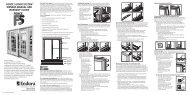
Pre-Hanger Installation Instructions - Endura Products
Pre-Hanger Installation Instructions - Endura Products
Pre-Hanger Installation Instructions - Endura Products
- No tags were found...

You also want an ePaper? Increase the reach of your titles
YUMPU automatically turns print PDFs into web optimized ePapers that Google loves.
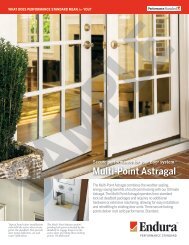
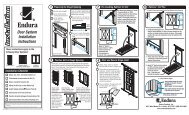
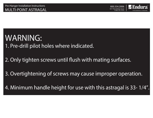
<strong>Pre</strong>-<strong>Hanger</strong> <strong>Installation</strong> <strong>Instructions</strong> 800.334.20068817 West Market StreetMULTI-POINT ASTRAGALColfax, NC 27235WARNING:1. <strong>Pre</strong>-drill pilot holes where indicated.2. Only tighten screws until flush with mating surfaces.3. Overtightening of screws may cause improper operation.4. Minimum handle height for use with this astragal is 33- 1/4”.
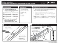
MULTI-POINT ASTRAGAL800.334.20068817 West Market StreetColfax, NC 272351Measure the Centerline distance between the lock pawls on the astragal.• Determine and mark the center line of both lock pawls.• Measure distance between the two centerlines. Measurement will end with 3/8”.• Record measurement for use in step 2b or 3.LockPawlC/LLockPawlC/L
MULTI-POINT ASTRAGAL800.334.20068817 West Market StreetColfax, NC 272352aKeeper Assembly Pocket Routing with <strong>Endura</strong> TemplateLOWER ROUT:• Choose correct pattern based on panel thickness(See Note 1)• Position router templateRout depth from stile face = 0.44” +0.000-0.025”Rout corner radius = 1/4”+.0002.531-.0250.440 +.000-.025• Securely clamp router template in placeDEEPACTIVE PANELSTRIKE SIDEROUTER TEMPLATE(template is symmetrical)1.031+.000-.025ROUT DETAIL(Center on panel thickness)R 0.2505-5/16”NOTE:1 Router template has two patterns.One for 1-3/4” thick panels and one for1-11/16” thick panels.CLAMPCLAMPDOOR BOTTOM2 Router Template requires use of a 5/8”diameter collar and a 1/2” bit.IMPORTANT: USE CARE IN INSERTION AND REMOVAL OF ROUTER BIT TO AVOID DAMAGE TO ROUTER TEMPLATE
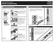
MULTI-POINT ASTRAGAL800.334.20068817 West Market StreetColfax, NC 272351b 2bKeeper Assembly Pocket Routing with <strong>Endura</strong> TemplateUPPER ROUT• Position router templateUse measurement of distance between the lock pawlsCenterline on the astragal from step 1, and add 5- 5/16”.Note: Distance will always end in 11/16” and will vary in 1”increments.EXAMPLE: If the Centerline distance is 60- 3/8”, the templateposition would be 65- 11/16”. (60-3/8” + 5- 5/16” = 65- 11/16”)• Rout depth from stile face = 0.44” +0.00-0.025”• Rout corner radius = 1/4”+.0002.531-.0250.440 +.000-.025DEEP• Securely clamp router template in placeCLAMP1.031+.000-.025R 0.250ROUT DETAIL(Center on panel thickness)TEMPLATEPOSITIONROUTER TEMPLATEDOORBOTTOM
MULTI-POINT ASTRAGAL800.334.20068817 West Market StreetColfax, NC 272353Keeper Assembly Pocket - Routing Without <strong>Endura</strong> TemplateDetermine the Rout Pocket Position .Use measurement of distance between the lock pawlsCenterline on the astragal from step 1, and add 7 -1/16”.Note: Distance will always end in 7/16” and will vary in 1” increments.EXAMPLE: If the Centerline distance is 60- 3/8”, the pocketposition would be 67- 7/16”. (60-3/8” + 7- 1/16” = 67- 7/16”)+.0002.531-.0250.440 +.000-.025DEEP1.031+.000-.025ROUT DETAILR 0.250(Center on panel thickness)ROUT POCKETPOSITION7-1/16”DoorBottom
<strong>Pre</strong>-<strong>Hanger</strong> <strong>Installation</strong> <strong>Instructions</strong>: <strong>Pre</strong>paration Steps 800.334.20068817 West Market StreetMULTI-POINT ASTRAGALColfax, NC 272354Keeper Assembly Attachment1NOTE: KEEPER PIVOT ARM RESTS IN UPWARD POSITION2INSERT ASSEMBLY INTO EACH POCKET AS SHOWNOPEN SIDE OF KEEPER MUST FACE BARRELOF HINGES WHEN INSTALLED3SECURE EACH ASSEMBLY WITH (2) #8 X 1” SCREWS4ENSURE PIVOT ARM MOVES FREELYIMPORTANT: IMPORTANT: OVERTIGHTENING OF SCREWS MAY CAUSE IMPROPER OPERATION
MULTI-POINT ASTRAGAL800.334.20068817 West Market StreetColfax, NC 272355Inactive Panel <strong>Pre</strong>p with <strong>Endura</strong> Template1 2Mark Rout LocationPlace Router TemplateDoor TopDistance = Active paneldeadboltcenter lineDoor TopPosition bottom edgeof template slot 1/2” belowdeadbolt center lineDoor TopDoorPanelDeadbolt centerline locationLine up lower small markon router template withdeadbolt centerline3RoutPocketUsing 1/2” router bit with 5/8”diameter collar, rout slot in door0.44” deep4Finished Rout0.44” deepDoor TopDoor TopInactive Panel <strong>Pre</strong>p Without <strong>Endura</strong> Template1 23Mark Rout Location Drill Two Holes Drill Final HoleDoor TopDrill hole: 1”diameter x 7/16” deepDistance = Active paneldeadbolt center lineDoor TopDrill 2ndhole abovethe 1st hole 1”diameter x 7/16” deep1.250 center tocenterDoor TopDrill 3rd hole:1” x 7/16”deep directlybetween hole1 and hole 2
Wide FlangeWide FlangeMULTI-POINT ASTRAGAL<strong>Installation</strong> Steps800.334.20068817 West Market StreetColfax, NC 272351Remove Shipping Clip2Verify Astragal Length and Handing3Verify Astragal FitUsing a Phillips head screw driver, remove and discardthe two screws from the back of the astragal, whichhold the deadbolt actuator in position during shipping.Discard the shipping clip and screws.ScrewShipping ClipFlush withend of panelLip should fit snugagainst the door panelEnd of DoorTopBottomFor door panels with a thickness of 1-11/16”apply available B-Seal gasket to accommodategap between panel face and astragal4 Position Astragal on Passive Door5• For inswing applications, thetrim cap is to the exterior sideSecure Flush Bolt Actuator• Secure with two, #8 x 1-5/8” paintedhardware screws• For outswing applications, thetrim cap is to the interior side• Peel tape backing to secureastragal to passive door• Before pressing tape in place,ensure the top of the astragal isflush with top of doorEnd of DoorTrim CapTopFlush with topof door panelIMPORTANT: OVERTIGHTENING OF SCREWS MAY CAUSE IMPROPER OPERATION
MULTI-POINT ASTRAGAL<strong>Installation</strong> Steps800.334.20068817 West Market StreetColfax, NC 272356Secure Upper and Lower BoltsSecure upper and lower bolts with(2) #8 x 1-5/8” painted hardwarescrews each71Anchoring the AstragalRemove bolt sleeveretainers oneach end2Slide out bolt sleeve, install (3) #8 x 1”screws (do not overtighten)3 Slide out bolt sleeve, install (2) #8 x 1”screws (do not overtighten)Ensure gasket is seated.GasketEnsure gasket is seated.Replace bolt sleeveReplace bolt sleeveReplace RetainerReplace RetainerBolt SleeveRetainerBolt SleeveUpper BoltGasketLower BoltRetainerNote: Take care not todamage pads duringremoval and installationof lower bolt sleeveIMPORTANT: OVERTIGHTENING OF SCREWS MAY CAUSE IMPROPER OPERATIONIMPORTA T:
MULTI-POINT ASTRAGAL<strong>Installation</strong> Steps800.334.20068817 West Market StreetColfax, NC 2723522Measure, Cut and Install Trim1Measure space between installed components (2 areas)12Cut body trim to length (2 areas)3Install body trim (2 areas)23Cut &Install1Measure23Cut &Install1 Measure
MULTI-POINT ASTRAGAL<strong>Installation</strong> Steps800.334.20068817 West Market StreetColfax, NC 2723522aDisengaging Bolts For Shipping1 2Remove Lower TrimRotate Lever 90 0• Rotate bolt actuatorlever upward 90 0• Remove trim stripbetween lower boltand lever assembly• Repeat for trim at top bolt(if installed)3WeatherstripDisengage Drive Lugs• Locate bottom drive lug andlinkage slot (on side nextto weatherstrip)Slide LugsTowards Center• Disengage drive lug from linkage by rotatinglug arm upward and away from slot• Slide lug and bolt pin towards centerof astragalLinkage Slot• Repeat steps above for the top bolt drive lugDrive Lug
MULTI-POINT ASTRAGAL<strong>Installation</strong> Steps800.334.20068817 West Market StreetColfax, NC 2723526Apply Paint Covers to KeepersPlace adhesive backedprotective cover overeach keeper assembly