Ultimate Multi-Point Astragal and Ultimate Flip Lever Astragal 1 2 3
Cut Down - Endura Products
Cut Down - Endura Products
- No tags were found...

Create successful ePaper yourself
Turn your PDF publications into a flip-book with our unique Google optimized e-Paper software.
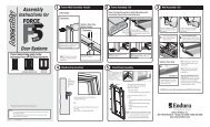
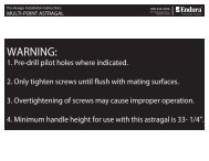
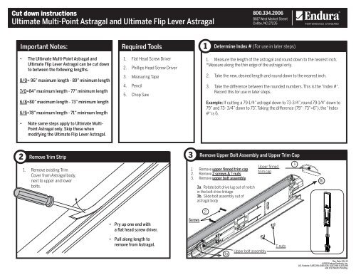
Cut down instructions<strong>Ultimate</strong> <strong>Multi</strong>-<strong>Point</strong> <strong>Astragal</strong> <strong>and</strong> <strong>Ultimate</strong> <strong>Flip</strong> <strong>Lever</strong> <strong>Astragal</strong>800.334.20068817 West Market StreetColfax, NC 27235Important Notes:Required Tools1Determine Index # (For use in later steps)• The <strong>Ultimate</strong> <strong>Multi</strong>-<strong>Point</strong> <strong>Astragal</strong> <strong>and</strong><strong>Ultimate</strong> <strong>Flip</strong> <strong>Lever</strong> <strong>Astragal</strong> can be cut downto between the following lengths.8/0= 96” maximum length - 89” minimum length7/0=84” maximum length - 77” minimum length6/8=80” maximum length - 73” minimum length6/6=78” maximum length - 71” minimum length• Note some steps apply to <strong>Ultimate</strong> <strong>Multi</strong>-<strong>Point</strong> <strong>Astragal</strong> only. Skip these whenmodifying the <strong>Ultimate</strong> <strong>Flip</strong> <strong>Lever</strong> <strong>Astragal</strong>.1. Flat Head Screw Driver2. Phillips Head Screw Driver3. Measuring Tape4. Pencil5. Chop Saw1. Measure the length of the astragal <strong>and</strong> round down to the nearest inch.*Measure along the thin edge of the astragal only.2. Take the new, desired length <strong>and</strong> round down to the nearest inch.3. Take the difference between the rounded numbers. This is the “Index #“.Record this for use in later steps.Example: If cutting a 79-1/4” astragal down to 73-3/4”, round 79-1/4” down to79” <strong>and</strong> 73- 3/4” down to 73”. Taking the difference (79”- 73”=6”), the “Index#“ is 6.2Remove Trim Strip1. Remove existing TrimCover from <strong>Astragal</strong> body,next to upper <strong>and</strong> lowerbolts.3Remove Upper Bolt Assembly <strong>and</strong> Upper Trim Cap1. Remove upper finned trim cap2. Remove 2 screws & T-nuts3. Remove upper bolt assembly3a. Rotate bolt drive lug out of notchin the bolt drive linkage3b. Slide bolt assembly out ofastragal body2.Upper finnedtrim cap1.3b.• Pry up one end witha flat head screw driver.Screws• Pull along length toremove from <strong>Astragal</strong>.3a.Upper bolt assemblyT-nutsRev. Date 8.14.13©2013 Endura Products, Inc.U.S. Patents: 5,857,291; 6491,326; 8,157,298; 8,157,299<strong>and</strong> U.S Patents Pending.
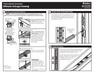
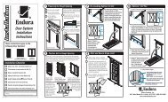
Cut down instructions<strong>Ultimate</strong> <strong>Multi</strong>-<strong>Point</strong> <strong>Astragal</strong> <strong>and</strong> <strong>Ultimate</strong> <strong>Flip</strong> <strong>Lever</strong> <strong>Astragal</strong>800.334.20068817 West Market StreetColfax, NC 272354ScrewsRemove Lower Bolt Assembly <strong>and</strong> Lower Trim Cap1. Remove lower trim cap2. Remove 2 screws & T-nuts3. Remove lower bolt assembly3a. Rotate bolt drive lug out of notchin the bolt drive linkage3b. Slide bolt assembly out ofastragal body2.Lower outswingtrim cap1.3b.Lower inswing trimcap5Remove Shipping Clip (For <strong>Multi</strong>-<strong>Point</strong> <strong>Astragal</strong> only)1. Using a Phillips head screw driver, remove <strong>and</strong>discard the two screws from the back of theastragal, which hold the deadbolt actuator inposition during shipping.2. Discard the shipping clipScrewShipping Clip3a.Lower bolt assemblyT-nuts6Remove Deadbolt Actuator(For <strong>Multi</strong>-<strong>Point</strong> <strong>Astragal</strong> only)7Remove Lower Actuator Cam (For <strong>Multi</strong>-<strong>Point</strong> <strong>Astragal</strong> only)1. Remove Actuatorcover.2. Rotate actuator outof astragal bodytoward narrow edgeof astragal.1. Locate “T” bar on the thin edge of the <strong>Astragal</strong>.Slide the “T” bar out of the astragal body lowerend, far enough to remove the lower actuatorcam.2. Remove the actuator cam.3. Place actuator cam aside for later reassembly(step 9)4. Slide the “T” bar back intothe astragal.Actuator Cam“T” bar*Bottom of astragal
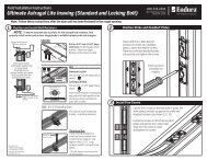
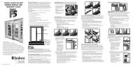
Cut down instructions<strong>Ultimate</strong> <strong>Multi</strong>-<strong>Point</strong> <strong>Astragal</strong> <strong>and</strong> <strong>Ultimate</strong> <strong>Flip</strong> <strong>Lever</strong> <strong>Astragal</strong>800.334.20068817 West Market StreetColfax, NC 272358Shorten “T” Bar at Upper End (For <strong>Multi</strong>-<strong>Point</strong> <strong>Astragal</strong> only)1. Locate “T” bar on the thin edge of the upper end of theastragal.2. Slide the “T” bar up until the removable segments areexposed.3. Remove an equal number of segments to the “index #”from step 1.1.2.*Top of astragal3a. To remove segments, first lift up on end of“T” bar to disengage it from the first segment.3b. Count number of segments to be removed <strong>and</strong> lift upto remove.3c. Replace end of “T” bar by pressing it down onto theremaining end segment.3a.*Top of astragalRemovable segments3b.Discard3c.9 Replace Actuator Cam(For <strong>Multi</strong>-<strong>Point</strong> <strong>Astragal</strong> only)1. Slide “T” Bar back down out of the bottom of theastragal body.1.*Top of astragal* “T” bar may hang up in the flip lever. If thisoccurs, push “T” bar away from flip lever <strong>and</strong> jigglethe flip lever while trying to slide the “T” bar untilthe “T” bar passes through.2. Reattach lower cam, making sure to orient camcorrectlyNote: Cam will snap firmly into “T” bar mating slot.3. Slide “T”- Bar back into astragal body.Actuator Cam2.*Bottom of astragal3.“T” barOrientationCam“T” bar
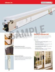
Cut down instructions<strong>Ultimate</strong> <strong>Multi</strong>-<strong>Point</strong> <strong>Astragal</strong> <strong>and</strong> <strong>Ultimate</strong> <strong>Flip</strong> <strong>Lever</strong> <strong>Astragal</strong>800.334.20068817 West Market StreetColfax, NC 2723510 Remove <strong>Flip</strong> <strong>Lever</strong> Mounting Screw!Skip to step 18 if “Index #” from step 1 is 4 or less.Screw• Engage flip lever to expose center mounting screw. • Remove the mounting screw <strong>and</strong> be sure to keep T-nut forlater use.T-nut11 Remove the <strong>Flip</strong> <strong>Lever</strong>.12 Mark <strong>Flip</strong> <strong>Lever</strong> Lug LocationsCenter screw/ T-Nut locationLower Drive RodMarkUpper Drive RodNote: the marked notch on the upper drive rod maynot be the endmost notch.• Remove flip lever assembly from astragal body by liftingstraight out.• Align lower flip lever lug to notch in lower drive rod.• On side of astragal body, mark location of upper <strong>and</strong> lower drive rod notch centers aligned with flip leverlugs. These may not be in the end most notches.
Cut down instructions<strong>Ultimate</strong> <strong>Multi</strong>-<strong>Point</strong> <strong>Astragal</strong> <strong>and</strong> <strong>Ultimate</strong> <strong>Flip</strong> <strong>Lever</strong> <strong>Astragal</strong>800.334.20068817 West Market StreetColfax, NC 2723513 Move “J” Bar Engagement with <strong>Flip</strong> <strong>Lever</strong>14 Orient <strong>Flip</strong> <strong>Lever</strong> Assembly.• Subtract 4 from the “index #” from step 1. Slide upper drive roddown that many notches so that the new notch lines up with themark on the astragal made in step 12.Example: If the “index #” is 6, slide the drive rod down 2 notchessince 6 - 4 = 2.<strong>Flip</strong> <strong>Lever</strong> Original Position MarksUpper Drive RodBOTTOMTOP<strong>Flip</strong> <strong>Lever</strong> Original Position Marks• Properly orient new flip lever assembly.• The flip lever should be in the extended position, with theh<strong>and</strong>le arm towards the bottom of the astragal.15 Align <strong>Flip</strong> <strong>Lever</strong> Assembly.16 Place New <strong>Flip</strong> <strong>Lever</strong> Assembly• Position flip lever assembly to align withdrive rod notch marks on the astragalbody.• Center the flip lever assembly over theastragal channel <strong>and</strong> drop straight downinto position.• Once properly seated,the flip lever assemblyrests evenly on theastragal’s side legs.It may be necessary to wiggle theassembly to ensure that the drive lugsproperly mate with the drive rod notches.Align!DO NOT ACTUATE FLIP LEVERUNTIL SCREW IS REINSERTED(SEE STEP 17)Align
Cut down instructions<strong>Ultimate</strong> <strong>Multi</strong>-<strong>Point</strong> <strong>Astragal</strong> <strong>and</strong> <strong>Ultimate</strong> <strong>Flip</strong> <strong>Lever</strong> <strong>Astragal</strong>800.334.20068817 West Market StreetColfax, NC 2723519 Install Lower Shoot Bolt <strong>and</strong> Engage Upper Shoot Bolt Drive Lug.1. Ensure flip lever is in the retracted position.2. Slide Lower bolt assembly into its originalposition in the astragal body. Bolt should berelatively flush with the end of the astragal.Lift lock leg as bolt is moved into position.*Note correct lug orientation. “THIS SIDE UP”printing should be visible on lug.Lower bolt assembly2.4.THIS SIDE UP3. Engage the lower Shoot bolt drive lug in theadjacent drive rod notch4. Install screws <strong>and</strong> T-nuts into originalsmaller holes in the bolt.5.5. Install the Lower trim capFinned Trim Cap3Outswing Only* Bottom of astragal20Push “T” Bar into Place (For <strong>Multi</strong>-<strong>Point</strong> <strong>Astragal</strong> only)Slide the “T” bar down until the lower actuator cam is positioned against the lower lock leg. Liftthe lock leg then move the “T” bar until the actuator cam mates with lower lock leg.Lock Leg*Bottom of astragal
Cut down instructions<strong>Ultimate</strong> <strong>Multi</strong>-<strong>Point</strong> <strong>Astragal</strong> <strong>and</strong> <strong>Ultimate</strong> <strong>Flip</strong> <strong>Lever</strong> <strong>Astragal</strong>800.334.20068817 West Market StreetColfax, NC 2723521Install Upper Shoot Bolt <strong>and</strong> Engage Upper Shoot Bolt Drive Lug.1. Ensure flip lever is in retracted position2. Slide upper shoot bolt assembly into astragal body until the bolt end is flush with the end of the astragal. Then continue sliding the bolt inward until it finds the nearest set of mountingholes. The lock leg will need to be lifted to allow engagement with the actuator cam.*Note correct lug orientation. “THIS SIDE UP” printing should be visible on lug.3. Install screws <strong>and</strong> T-nuts into original smaller holes in the bolt.4. Engage the upper shoot bolt drive lug in the adjacent drive rod notch.5. Install the upper trim cap.THIS SIDE UP4. 3.2.5*( For <strong>Ultimate</strong> <strong>Multi</strong>-<strong>Point</strong> astragals only)When installing upper shoot bolt, make sure the upper lock legis seated in the actuator cam.* Top of astragal
Cut down instructions<strong>Ultimate</strong> <strong>Multi</strong>-<strong>Point</strong> <strong>Astragal</strong> <strong>and</strong> <strong>Ultimate</strong> <strong>Flip</strong> <strong>Lever</strong> <strong>Astragal</strong>800.334.20068817 West Market StreetColfax, NC 2723522Replace Dead Bolt Actuator (For <strong>Multi</strong>-<strong>Point</strong> <strong>Astragal</strong> only)23Replace Actuator Cover(For <strong>Multi</strong>-<strong>Point</strong> <strong>Astragal</strong> only)1. Measure <strong>and</strong> markastragal body atthe center of thedeadbolt position.2. Rotate actuatorinto astragal bodystarting at narrowedge of astragalusing mark to lineup score line onactuator body withcenter of passivepanel deadbolt bore.3. Hold down lock legon bottom boltEnsure the teeth onthe actuator adjusterengage the rack teethon adjustment insert.Move adjustmentinsert ifnecessary.AdjustmentInsertActuatorAdjusterRotate actuator intoward the wideredge of astragal body.1. Hold actuator in place2. Replace cover3. Slide trim up to <strong>and</strong> under actuator.TrimNote: Hold ActuatorIn PositionActuator coverCAUTION - Do notoperate deadboltactuator withoutcover in place.Failure to do somay result in thesystem remainingin the lockedposition.24 Verify Function25A.Operate <strong>Flip</strong> <strong>Lever</strong>• Ensure bolt sleeve<strong>and</strong> pins movebetween engaged<strong>and</strong> disengagedpositions.Install on Door Panel.•The astragal is now ready to be installed onthe door panel.• Please see separate installation instructions.Upper BoltLower BoltNote: if lower bolt does not freely move, lever may need to be cycled several times. Also check that the screws in astragal below boltsare flush with astragal body.B. Operate ActuatorCam• Ensure top <strong>and</strong>bottom lock legsmove betweenengaged <strong>and</strong>disengaged positions.Caution - Do not operatedeadbolt actuator withoutcover in place. Failure to doso may result in the lockleg remaining in the lockedposition.Lock Leg