<strong>EC</strong> <strong>axial</strong> <strong>fans</strong> “low pressure”Ø 560 - Ø 990– Material: Carrying ring: Steel, galvanised, primed and coated in black plasticWall ring: Sheet steel, pre-galvanised, primed and coated in black plasticBlades (5): B D E Pressed-on round sheet steel plate; A C F Insertion part made ofsheet aluminium; Both versions are coated and extrusion-coated in PP plasticsRotor: Primed and coated in blackElectronics enclosure: Die-cast aluminium, coated in black– Direction of rotation: A B C clockwise, D E F counter-clockwise seen on rotor– Type of protection: IP 54 (acc. to EN 60529)– Insulation class: A B C D E "B" ("F" applying to the main components as per EN), F "F"– Mounting position: Shaft horizontal or rotor on top– Condensate discharges: Stator-side– Mode of operation: Continuous operation (S1)– Bearings: Maintenance-free ball bearingsNominal dataBlade angleCurveNominalvoltage rangeFrequencySpeed/rpm (1)Max.Input power (1)Max.Current draw (1)Max. back pressurePerm. amb. temp.Mass withoutattachmentsTechnical features andelectr. connectionsTypeMotorVAC Hz rpm kW A Pa °C kg*3G 560 M3G 112-EA-5° A1~ 200-277 50/60 1000 0,40 1,80 100 -25..+60 7,2S. 27 / L3)*3G 630 M3G 112-GA -5° B 1~ 200-277 50/60 1000 0,72 3,20 140 -25..+60 9,3 S. 27 / L3)*3G 710 M3G 112-IA 0° C 1~ 200-277 50/60 830 0,70 3,10 100 -25..+60 12,0 S. 27 / L3)*3G 800 M3G 112-IA 0° D 1~ 200-277 50/60 710 0,73 3,20 100 -25..+60 12,1 S. 27 / L3)*3G 910 M3G 112-IA 0° E 1~ 200-277 50/60 590 0,58 2,60 80 -25..+60 12,2 S. 27 / L3)*3G 990 M3G 150-FF -5° F 1~ 200-277 50/60 820 1,39 6,10 70 -25..+50 22,7 S. 28 / L9)subject to alterations(1) Nominal data in operating point with maximum load and 230 VACCurvesnrpmP eWIAL W AdB(A)SFPW/(1000m 3 /h)p sf Pa1501401301201101009080706050403020100,10,20,30,40,5in H 2 O0q V3B3 3 3DA33F2 2 2 2 22<strong>EC</strong>1 1 1 1 15000 10000 150004000 8000 12000 16000 20000 24000 280001cfmm 3 /hAir per<strong>for</strong>mance measuredas per: ISO 5801,Installation category A,in ebm-papst full nozzlewithout protection againstaccidental contactSuction-side noise levels:L W A as per ISO 13347,L p A measured at 1 m distanceto fan axisThe acoustic values given areonly valid under the measurmentconditions listed andmay vary depending on theinstallation situation.With any deviation to the standardsetup, the specific valueshave to be checked and reviewedonce installed or fitted!For detailed in<strong>for</strong>mationsee page 30 ff.AAABBBCCCDDDEEEFFF1231231231231231231000100010001000100010008308308307107107105905905908208208202933314004625187204485257004625417303464455801010117013901,291,461,802,112,363,202,102,413,102,152,493,201,642,072,604,425,106,1067666971697169687370676967657180797835,143,374,138,245,994,831,139,671,526,534,369,618,227,058,533,141,353,98
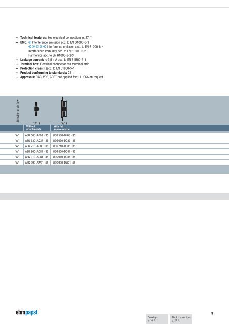
– Technical features: See electrical connections p. 27 ff.– EMC: F Interference emission acc. to EN 61000-6-3A B C D E Interference emission acc. to EN 61000-6-4Interference immunity acc. to EN 61000-6-2Harmonics acc. to EN 61000-3-2/3– Leakage current: < 3.5 mA acc. to EN 61800-5-1– Terminal box: Electrical connection via terminal strip– Protection class: I (acc. to EN 61800-5-1)– Product con<strong>for</strong>ming to standards: CE– Approvals: CCC; VDE, GOST are applied <strong>for</strong>; UL, CSA on requestDirection of air flow"A" ❯Withoutattachments"A" ❯With fullsquare nozzle"A" A3G 560-AP68 -35 W3G 560-DP68 -35"A" A3G 630-AQ37 -35 W3G 630-DQ37 -35"A" A3G 710-AO85 -35 W3G 710-DO85 -35"A" A3G 800-AO81 -35 W3G 800-DO81 -35"A" A3G 910-AO84 -35 W3G 910-DO84 -35"A" A3G 990-AW21 -55 W3G 990-DW21 -55Drawingsp. 10 ff.Electr. connectionsp. 27 ff.9


![Succesvol seminar [PDF] 314,2 kB - ebm-papst](https://img.yumpu.com/52907957/1/184x260/succesvol-seminar-pdf-3142-kb-ebm-papst.jpg?quality=85)
![magº 2013-1 [PDF] - ebm-papst](https://img.yumpu.com/52907773/1/190x252/mag-2013-1-pdf-ebm-papst.jpg?quality=85)