Development of injection of reduction gas into the blast ... - klimazwei
Development of injection of reduction gas into the blast ... - klimazwei
Development of injection of reduction gas into the blast ... - klimazwei

You also want an ePaper? Increase the reach of your titles
YUMPU automatically turns print PDFs into web optimized ePapers that Google loves.
<strong>Development</strong> <strong>of</strong> <strong>injection</strong> <strong>of</strong> <strong>reduction</strong> <strong>gas</strong><br />
<strong>into</strong> <strong>the</strong> <strong>blast</strong> furnace shaft<br />
Joachim Buchwalder 1 , Jörg Mernitz 1 , Günter Harp 2 , Michael, Hensmann 2 ,<br />
Christian Reu<strong>the</strong>r 3 and Manfred Schingnitz 3<br />
1 Arcelor Eisenhüttenstadt GmbH, Werkstrasse 1, 15890 Eisenhüttenstadt Germany<br />
2 Betriebsforschungsinstitut VDEh-Institut für angewandte Forschung GmbH<br />
Sohnstrasse 65, 40237 Düsseldorf, Germany<br />
3 Siemens Fuel Gasification Technology GmbH, Halsbrücker Str. 34, 09599 Freiberg, Germany<br />
Abstract<br />
The <strong>injection</strong> <strong>of</strong> hot reducing <strong>gas</strong> <strong>into</strong> <strong>the</strong> shaft was investigated at Arcelor<br />
Eisenhüttenstadt. The <strong>blast</strong> furnace No. 1 (BF 1) was modified for <strong>the</strong><br />
investigations with additional tuyeres at <strong>the</strong> BF shaft and <strong>the</strong> installation <strong>of</strong> hot <strong>gas</strong><br />
generators (HGG). The hot reducing <strong>gas</strong> was generated by partial oxidation <strong>of</strong><br />
natural <strong>gas</strong> with oxygen within 4 HGG and injected <strong>into</strong> a fourth <strong>of</strong> <strong>the</strong> total BF<br />
cross-section. First CFD calculations for prediction <strong>of</strong> expected penetration depth<br />
were carried out. The penetration depth during experimental <strong>reduction</strong> <strong>gas</strong> <strong>injection</strong><br />
was determined by He tracing tests. The <strong>reduction</strong> degree <strong>of</strong> <strong>the</strong> burden material<br />
was determined by core drilling exercises and analysis <strong>of</strong> <strong>the</strong> core material.<br />
The investigation shows, that <strong>the</strong> <strong>gas</strong> <strong>injection</strong> <strong>into</strong> <strong>the</strong> shaft seems to be a key<br />
technology to raise <strong>the</strong> use <strong>of</strong> additional reductants for <strong>the</strong> <strong>blast</strong> furnace process<br />
and to become more flexible in reductant application.<br />
Key words: Blast furnace, CO2-emission, <strong>injection</strong>, partial oxidation, reducing<br />
agent, reducing <strong>gas</strong>.<br />
1. Introduction<br />
The coke consumption <strong>of</strong> <strong>the</strong> BF-process has been minimized by optimization <strong>of</strong><br />
burden technique and application <strong>of</strong> additional reductant <strong>injection</strong> through <strong>the</strong><br />
tuyeres. The minimum consumption <strong>of</strong> reducing agents with <strong>the</strong> best-availabletechnology<br />
(BAT) was calculated with a complex BF calculation model by Schmöle<br />
and Lüngen [1] to 300 kg/tHM coke and 174 kg/tHm pulverized coal. The reductant<br />
consumption as well as <strong>the</strong> specific productivity has reached nearly <strong>the</strong> technical<br />
process limits. New concepts for lowering <strong>the</strong> reductant consumption and <strong>the</strong> CO2emission<br />
are announced under <strong>the</strong> term “nitrogen free BF-Process” and “plasma<br />
heated BF-Process” [2-4]. Those concepts need greater process modifications.<br />
At Arcelor Eisenhüttenstadt process modification with <strong>injection</strong> <strong>of</strong> hot reducing <strong>gas</strong><br />
<strong>into</strong> <strong>the</strong> shaft is investigated. The aim is to increase <strong>the</strong> degree <strong>of</strong> indirect <strong>reduction</strong><br />
<strong>of</strong> <strong>the</strong> burden by <strong>injection</strong> <strong>of</strong> reducing <strong>gas</strong> <strong>into</strong> <strong>the</strong> shaft within <strong>the</strong> <strong>the</strong>rmal reserve<br />
zone and lowering <strong>the</strong> specific reducing <strong>gas</strong> amount generated at normal tuyere<br />
level. The BF 1 was modified for <strong>the</strong> investigations with additional tuyeres at <strong>the</strong> BF<br />
298
upper belly area and <strong>the</strong> installation <strong>of</strong> so called hot <strong>gas</strong> generators (HGG) for <strong>the</strong><br />
production and <strong>injection</strong> <strong>of</strong> hot reducing <strong>gas</strong>.<br />
2. BF-Process with <strong>injection</strong> <strong>of</strong> hot reducing <strong>gas</strong><br />
Several <strong>the</strong>oretical and operational stages were carried out for <strong>the</strong> modification <strong>of</strong><br />
<strong>the</strong> BF-process. The procedure <strong>of</strong> investigation is listed as follows.<br />
� definition <strong>of</strong> <strong>the</strong> required consumption <strong>of</strong> <strong>the</strong> reducing <strong>gas</strong> (equilibrium<br />
calculations)<br />
� CFD calculation for determination <strong>of</strong> expectable penetration depth <strong>of</strong> <strong>the</strong><br />
reducing <strong>gas</strong> <strong>into</strong> <strong>the</strong> BF-shaft<br />
� energy and mass balance calculations for BF operation with <strong>injection</strong> <strong>of</strong> hot<br />
reducing <strong>gas</strong><br />
� technical development <strong>of</strong> HGG<br />
� implementation and commissioning <strong>of</strong> HGG at BF 1<br />
� operational trials at BF 1 with <strong>injection</strong> <strong>of</strong> hot reducing <strong>gas</strong><br />
� optimisation <strong>of</strong> <strong>the</strong> <strong>injection</strong> <strong>of</strong> hot reducing <strong>gas</strong> <strong>into</strong> <strong>the</strong> BF shaft<br />
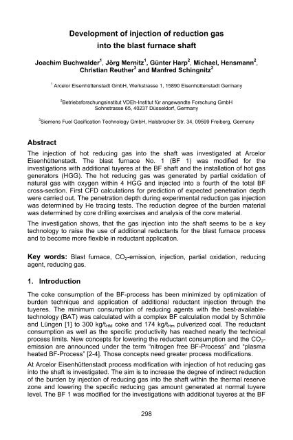
The <strong>injection</strong> <strong>of</strong> hot reducing <strong>gas</strong> was carried out at BF 1 (Arcelor<br />
Eisenhüttenstadt) (figure 1) with a av. production <strong>of</strong> about 1,600 tHM/d.<br />
Figure 1: BF 1 at Arcelor Eisenhüttenstadt<br />
299
The operating data <strong>of</strong> BF 1 at Arcelor Eisenhüttenstadt are shown in table 1. In<br />
addition to <strong>the</strong> usual reductant coke with a consumption <strong>of</strong> 377 kg/tHM oil and<br />
plastics are injected with a total amount <strong>of</strong> 85 kg/tHM. The BF is operated with a<br />
nominal <strong>blast</strong> flow rate <strong>of</strong> 71,000 m 3 /tHM, a <strong>blast</strong> pressure <strong>of</strong> 1.9 bar (abs.), and an<br />
oxygen content <strong>of</strong> approx. 24 % in <strong>the</strong> <strong>blast</strong>.<br />
hot metal:<br />
av. production [tHM/d] 1,576<br />
hot metal temperature [°C] 1,423<br />
reducing agents:<br />
dry coke rate [kg/tHm] 377<br />
oil [kg/tHM] 16<br />
plastics [kg/tHM] 67<br />
<strong>blast</strong>:<br />
<strong>blast</strong> flow rate [m 3 /h] 71,000<br />
<strong>blast</strong> pressure [bar] 1.9<br />
<strong>blast</strong> humidity [g/m 3 ] 13.3<br />
<strong>blast</strong> temperature [°C] 1,086<br />
oxygen content <strong>of</strong> <strong>blast</strong> [%] 23.6<br />
slag:<br />
spec. slag amount [kg/tHM] 215<br />
slag basicity (CaO/SiO2) 1.13<br />
Table 1: operating data <strong>of</strong> BF 1 at Arcelor Eisenhüttenstadt<br />
To minimize <strong>the</strong> investment costs for reducing <strong>gas</strong> generation for <strong>the</strong> operational<br />
scale trials <strong>the</strong> reducing <strong>gas</strong> was generated by partial oxidation <strong>of</strong> natural <strong>gas</strong> with<br />
oxygen within so called hot <strong>gas</strong> generators (HGG).<br />
Figure 2 shows a schematic diagram <strong>of</strong> <strong>the</strong> HGG developed by Siemens Fuel<br />
Gasification Technology. The HGG is designed for a maximum production <strong>of</strong><br />
reducing <strong>gas</strong> <strong>of</strong> about 2,400 m³/h.<br />
Figure 2: Schematic diagram <strong>of</strong> <strong>the</strong> HGG<br />
300
Oxygen is fed concentrically to <strong>the</strong> natural <strong>gas</strong>. At <strong>the</strong> tip <strong>of</strong> <strong>the</strong> HGG <strong>the</strong> ignition<br />
equipment is installed. The flame monitoring is done by a wave length sensitive<br />
detector at <strong>the</strong> rear side <strong>of</strong> <strong>the</strong> HGG. The central tube <strong>of</strong> <strong>the</strong> flame detector is<br />
cleaned with nitrogen as purge <strong>gas</strong>. The head <strong>of</strong> <strong>the</strong> HGG is hemispherical<br />
designed for <strong>the</strong> direct connection to <strong>the</strong> <strong>blast</strong> tuyere installed at <strong>the</strong> shaft shell. It<br />
is cooled with <strong>the</strong> available process water. The total length <strong>of</strong> <strong>the</strong> HGG is below 1.0<br />
m. The distance from <strong>the</strong> tip <strong>of</strong> <strong>the</strong> HGG to <strong>the</strong> inner side <strong>of</strong> <strong>the</strong> BF-shaft is approx.<br />
0.3 m.<br />
Figure 3 shows one HGG installed 5.35 m above <strong>the</strong> tuyere level.<br />
Figure 3: HGG installed at <strong>the</strong> shaft <strong>of</strong> BF 1<br />
Every HGG is supplied with <strong>gas</strong> and oxygen independently. The HGG operation is<br />
remote controlled by <strong>the</strong> control room personal.<br />
For <strong>the</strong> operational trials 4 HGG were installed within a fourth <strong>of</strong> <strong>the</strong> total BF crosssection.<br />
They are placed in <strong>the</strong> middle between <strong>the</strong> underlying tuyeres. The axial<br />
and transversal section <strong>of</strong> <strong>the</strong> modified BF 1 is shown in figure 4 and figure 5.<br />
One temperature and <strong>gas</strong> probe with a length <strong>of</strong> 0.5 m is located 1.2 m above<br />
HGG 10. An above burden probe equipped with 6 channels for temperature<br />
measurement and <strong>gas</strong> sampling is installed at <strong>the</strong> top <strong>of</strong> <strong>the</strong> shaft in <strong>the</strong> middle <strong>of</strong><br />
HGG 10 and 11. An additional above burden probe with also 6 channels for<br />
temperature measurement is installed at <strong>the</strong> opposite site.<br />
301
Figure 4: axial section <strong>of</strong> <strong>the</strong> modified BF 1.<br />
Figure 5: transversal section <strong>of</strong> <strong>the</strong> modified BF 1.<br />
302
3. Results <strong>of</strong> <strong>the</strong>oretical approach<br />
For a first determination <strong>of</strong> penetration depth CFD calculations were carried out by<br />
using <strong>the</strong> commercial FLUENT s<strong>of</strong>tware. The calculated percentage <strong>of</strong> reducing<br />
<strong>gas</strong> in <strong>the</strong> shaft for an <strong>injection</strong> velocity <strong>of</strong> about 170 m/s is shown in figure 6 as an<br />
example. In a distance <strong>of</strong> 790 mm from <strong>the</strong> shaft wall <strong>the</strong> percentage <strong>of</strong> reducing<br />
<strong>gas</strong> decreases to 50 %.<br />
Figure 6: calculated percentage <strong>of</strong> reducing <strong>gas</strong> in <strong>the</strong> shaft<br />
Table 2 shows <strong>the</strong> results <strong>of</strong> <strong>the</strong>rmochemical equilibrium calculations for <strong>the</strong><br />
product <strong>gas</strong> formed by partial oxidation <strong>of</strong> natural <strong>gas</strong> with oxygen. The resulting<br />
ratio between H2 and CO amounts approx. 2. The reducing <strong>gas</strong> contains about 5.6<br />
% <strong>of</strong> total oxidised components CO2 and H2O.<br />
set points:<br />
reducing <strong>gas</strong> flow [Nm 3 /h) 2,400<br />
reducing <strong>gas</strong> temperature [°C] 900<br />
input:<br />
natural <strong>gas</strong> flow [Nm 3 /h] 800<br />
oyxgen flow [Nm 3 /h] 470<br />
reducing <strong>gas</strong> composition:<br />
H2 [Vol.-%] 61.7<br />
CO [Vol.-%] 31.8<br />
CO2 [Vol.-%] 1.5<br />
CH4 [Vol.-%] 0.5<br />
N2 [Vol.-%] 0.4<br />
H2O [Vol.-%] 4.1<br />
Table 2: results <strong>of</strong> <strong>the</strong>rmochemical equilibrium calculations for <strong>the</strong> product <strong>gas</strong><br />
4. Operational results and obtained experience<br />
After commissioning <strong>the</strong> 4 HGG at BF 1 a trial period <strong>of</strong> approx. 6,500 h was<br />
started. The penetration depth <strong>of</strong> <strong>the</strong> injected hot reducing <strong>gas</strong> <strong>into</strong> <strong>the</strong> shaft was<br />
measured by He-tracing experiments by using <strong>the</strong> natural He-content <strong>of</strong> <strong>the</strong><br />
injected natural <strong>gas</strong> (250 to 300 ppm). During reducing <strong>gas</strong> <strong>injection</strong> <strong>gas</strong> sampling<br />
is done via 6 channel above burden probe at <strong>the</strong> top <strong>of</strong> <strong>the</strong> shaft (27.3 m above BF<br />
303
floor). The sampled <strong>gas</strong> was cleaned and subsequent detected with a process<br />
mass spectrometer on <strong>the</strong> components CO, CO2, H2, CH4, N2 and He. The period<br />
for scanning all 6 sampling points was fixed to 6 min. Selected results <strong>of</strong> <strong>the</strong> radial<br />
<strong>gas</strong> analyses are shown in <strong>the</strong> figures 7 and 8.<br />
Figure 7: selected results <strong>of</strong> <strong>the</strong> radial <strong>gas</strong> analyses for normal BF operation<br />
Figure 8: selected results <strong>of</strong> <strong>the</strong> radial <strong>gas</strong> analyses for BF operation<br />
with reducing <strong>gas</strong> <strong>injection</strong> (700 m 3 /h natural <strong>gas</strong>, 385 m 3 /h oxygen)<br />
As expected <strong>the</strong> radial He concentration for normal BF operation is nearly<br />
constant. Under conditions with reducing <strong>gas</strong> <strong>injection</strong> <strong>into</strong> <strong>the</strong> shaft <strong>the</strong> measured<br />
maximum He concentration is 20 ppm at 0.25 m <strong>of</strong>f <strong>the</strong> shaft wall. The value<br />
decreases with raised distance to <strong>the</strong> shaft wall. The influence <strong>of</strong> reducing <strong>gas</strong><br />
<strong>injection</strong> is perceptible up to a distance <strong>of</strong> 2 m from <strong>the</strong> shaft wall. The raised CH4<br />
concentration near <strong>the</strong> shaft wall is an indication for incomplete CH4 conversion.<br />
The CH4 conversion ranges between 80 and 90 %. The <strong>gas</strong> utilization (ETA CO)<br />
decreases in <strong>the</strong> direction to <strong>the</strong> middle <strong>of</strong> <strong>the</strong> BF shaft as a result <strong>of</strong> high<br />
percentage <strong>of</strong> coke in <strong>the</strong> centre <strong>of</strong> <strong>the</strong> shaft showing no difference to normal<br />
operation.<br />
The progress <strong>of</strong> burden material <strong>reduction</strong> is determined by core drilling exercises<br />
(figure 9) and analysis <strong>of</strong> <strong>the</strong> core material. Parts <strong>of</strong> <strong>the</strong> samples contain massive<br />
304
metallic iron. Its presence above <strong>the</strong> cohesive zone is a definite indication for high<br />
<strong>reduction</strong> work in accordance with <strong>the</strong> injected hot reducing <strong>gas</strong>.<br />
Figure 9: HGG tuyere opened for core drilling<br />
5. Conclusion<br />
The <strong>injection</strong> <strong>of</strong> hot <strong>gas</strong> <strong>into</strong> <strong>the</strong> BF shaft was successfully executed in operational<br />
trials at BF 1 at Arcelor Eisenhüttenstadt. The penetration depth <strong>of</strong> <strong>the</strong> hot reducing<br />
<strong>gas</strong> <strong>into</strong> <strong>the</strong> BF shaft has been evaluated <strong>the</strong>oretical by CFD calculation and<br />
experimental by He-tracing investigations. The progress <strong>of</strong> burden material<br />
<strong>reduction</strong> was determined by core drilling exercises and analysis <strong>of</strong> <strong>the</strong> core m<br />
aterial.<br />
The investigations show, that <strong>the</strong> shaft <strong>gas</strong> <strong>injection</strong> seems to be a key technology<br />
to raise <strong>the</strong> use <strong>of</strong> additional reductants for <strong>the</strong> <strong>blast</strong> furnace process and to<br />
become more flexible in reductant application.<br />
6. Acknowledgement<br />
This work has been financially supported by <strong>the</strong> BMBF (Bundesministerium für<br />
Bildung und Forschung) under FKZ 01 LK 0401, 01 LK 0402, 01 LK 0403. The<br />
authors wish to thank <strong>the</strong> BMBF for <strong>the</strong> financial assistance.<br />
The authors are responsible for <strong>the</strong> contents <strong>of</strong> this paper.<br />
7. References<br />
[1] Schmöle, P. and Lüngen, H. B.: Roheisenerzeugung im Hoch<strong>of</strong>en unter<br />
ökologischer Betrachtungsweise. Stahl und Eisen 124 (2004) Nr.5, s.27-34<br />
[2] Steiler, J. M. and Hanrot, F.: Present state and innovative issues for<br />
ironmaking. Science and technology <strong>of</strong> innovative ironmaking for aiming at<br />
energy half consumption. Tokio, 27./28.11.2003<br />
[3] Birat, J. P., Hanrot, F. and Danloy, G.: CO2 mitigation technologies in <strong>the</strong><br />
steel industry: a benchmark study based on process calculations. Scanmet<br />
II, Lulea, 6.6/9.6. 2004<br />
[4] Danloy, G., Korthas, B. Hanrot. F. and van der Stel, J.: Challenges <strong>of</strong> new<br />
<strong>blast</strong> furnace process development aiming at reducing CO2 emission.<br />
Symp. scrap substitutes and alternative ironmaking, Baltimore<br />
31.10./4.11.2004<br />
305