Horizontal Fiberglass Pumps
Horizontal Fiberglass Pumps - Techniques Des Fluides
Horizontal Fiberglass Pumps - Techniques Des Fluides

Create successful ePaper yourself
Turn your PDF publications into a flip-book with our unique Google optimized e-Paper software.
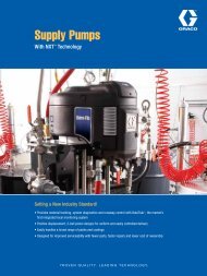
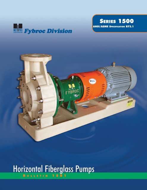
Fybroc DivisionSERIES 1500ANSI/ASME SPECIFICATION B73.1<strong>Horizontal</strong> <strong>Fiberglass</strong> <strong>Pumps</strong>B U L L E T I N15B1
FYBROC – THE LEADER IN CORROSION-RESISTANTFIBERGLASS PUMPING EQUIPMENTFybroc is an advanced technology pump manufacturerspecializing in reinforced composite centrifugalpumps, designed to handle corrosive liquids.Fybroc, the pioneer in the fiberglass pump field, continuesits position of leadership with its Series 1500pump. This line is the culmination of many years ofexperience in producing high quality, corrosion-resistantpumps.The Series 1500 combines an extensive knowledge ofmaterials and production techniques to provide exceptionalstructural integrity, excellent corrosion resistance, anddependable service in difficult operating environments.MATERIALS OF CONSTRUCTION ARE AVAILABLEFOR A WIDE RANGE OF CORROSIVE LIQUIDSOnly Fybroc has the flexibility in materials selection tosolve your difficult corrosive or abrasive pump problems.• VR-1, vinyl ester resin: used for the vast majority ofcorrosive applications including most acids,caustics, brines, sea water, and wastewater.• VR-1 BPO-DMA, vinyl ester resin with BPO-DMAcure system: used to accommodate applications forspecific corrosion resistance to bleaches such assodium hypochlorite (NaOCl) and hydrogenperoxide (H 2 O 2 ).• VR-1A, vinyl ester resin with abrasive resistantmaterial : used for pumping liquids with lowconcentration highly abrasive fines such asfly ash, diatomaceous earth or titaniumdioxide.• VR-1V, vinyl ester resin with syntheticveil: protection used specifically forfluoridic applications such ashydrofluoric acid (HF) and fluosilicicacid (H 2 SiF 6 ).• EY-2, epoxy resin: offers outstandingchemical resistance for aggressivechemical/compounds, acids,and solvents. Ideal for high concentrationsof sulfuric acid (up to98%).FDA COMPLIANCEThe Dow DERAKANE series epoxy vinyl ester resinutilized by Fybroc, when properly formulated and cured,will comply with the U.S. Food, Drug, and Cosmetic Act,as amended, and applicable FDA regulations (21 CFR177.2420). These resins may be used as articles or componentsof articles intended forrepeated use in contact with food,subject to certain limitationsdescribed in that regulation.For further information on corrosionresistance to specificchemicals, please refer tothe Fybroc website atwww.fybroc.com.2
DESIGN FEATURES OF THE SERIES 1500 PUMPThe Fybroc Series 1500 pump is designed for broadcorrosion-resistance through the use of high qualitymaterials and state-of-the-art engineering. Its simplicityand versatility make it the ideal choice for all demandingpumping requirements.The fiberglass components are manufactured utilizing theResin Transfer Molding technique which enables completecontrol of the fiberglass reinforcement in high stressareas. Metallic pump components are NOT in contactwith process fluids.12 13141110 94
1. ANSI/ASME B73.1 CONFOR-MANCE ensures maximum interchangeabilitywith existing metal ANSI pumps,thereby eliminating any need for pipingor foundation changes when up-gradingan installation to Fybroc Series 1500pumps.12345672. SMOOTH HYDRAULIC PASSAGESpromote increased pump efficiency.3. SINGLE ONE-PIECE GUSSETEDCASINGeasily withstands the rigors of normalplant piping loads.4. IMPELLER PUMP-OUT VANES andrelief holes minimize axial unbalanceand lower stuffing box pressure.5. ALLOY INSERT (integrally molded withimpeller) with rounded edges carriesimpeller torque loads with low stress.6. VERSATILE CASING COVER is suitablefor use with most single outside ordouble inside mechanical seals withoutmodifications. See page 7 for some ofthe most frequently used configurationsand page 8 for seal flush considerations.7. CONTINUOUS-STRAND FIBER-GLASS CONSTRUCTION for all wettedparts in either vinyl ester or epoxyresin provides maximum corrosion resistancefor a wide range of difficult liquids.8. CASING THROUGH-BOLTS maintaincasing o-ring seal integrity under allhydraulic operating conditions.9. INTEGRAL SHAFT SLEEVE designeliminates gaskets and o-rings andprotects the pump shaft from exposure tothe process fluid.10. LARGE-CAPACITY BEARINGS ensureoperating life well in excess of theminimum specified by ANSI/ASMEB73.1.811. EXTERNAL IMPELLER ADJUST-MENT allows field setting of impeller-tocasingclearance.12. HEAVY-DUTY SHAFT minimizesdeflec-tion to maximize mechanical seallife.13. POLYESTER THERMOSETTINGPOWDER COATED POWER FRAMEcomponents prevent external corrosion.14. LABYRINTH OIL SEALS nickel platedbronzefor longer life. Improved oilcontainment.5
DESIGN PROVIDES FOR MAXIMUMSEAL AND BEARING LIFEThe Series 1500 pumps have been designed to maximizethe life of bearings and mechanical seals which candeteriorate because of shaft deflection resulting fromradial thrust. Radial thrust is the force acting on the sideof an impeller as a result of the non-uniform distributionof pressure around the pump casing at off-peak operation.The magnitude of this thrust varies with the flow, but theamount of radial thrust can roughly be cut in half by utilizinga double volute casing. The solid line in the chart tothe right depicts the typical radial thrust characteristic of asingle volute casing. The dotted line portrays the use of adouble volute casing and the resulting reduction in radialthrust.The drawing at lower right shows the location of the“cutwater” in volute casings. The cutwater is the closeclearance extension of the casing located at the base ofthe volute. Also, shown in orange, is the second cutwateror “splitter” used in the double volute casing, whichchannels half of the flow to the pump discharge. The splitterreduces the pressure imbalance in the casing duringoff-peak flows and reduces both radial thrust and itsresulting shaft deflection. Fybroc uses double volute casingsin eleven of its larger pump sizes where, typically,radial thrust loadings are higher. See chart on page 9,Casing Data, Volute.% OF MAXIMUM RADIAL THRUST1009080706050403020100Single VoluteDouble Volute0 10 20 30 40 50 60 70 80 90 100 110 120 130 140% OF DESIGN FLOWCutwaterSplitterMATERIALS OF CONSTRUCTIONCOMPONENTCasingImpellerCoverGlandShaftBearing Hsg.AdapterHardwareO-RingsMATERIALSVR-1, VR-1 BPO-DMA, VR-1A, VR-1V, EY-2VR-1, VR-1 BPO-DMA, VR-1A, VR-1V, EY-2VR-1, VR-1 BPO-DMA, VR-1A, VR-1V, EY-2VR-1, VR-1 BPO-DMA, EY-2303SS (Optional 316SS)Polyester Thermosetting Powder Coated IronPolyester Thermosetting Powder Coated Iron303SS (Optional hardware is available)Viton A (Optional elastomers are available)Consult Factory for materials availability for your specific pump size.6
INTEGRAL IMPELLER AND• “ONE-PIECE” impeller and shaft sleeve• “NO” shaft sleeve o-rings required• Semi-open type with pump-out vanes and balanceholes designed to minimize axial unbalanceand lower stuffing box pressureMECHANICAL SEALFybroc Series 1500 pumps are available with a wide variety of mechanical seal arrangements. For corrosivefluid handling, single outside and double inside seals are recommended. The single outside seals havenon-metallic wetted parts and all metal components located outside the pump. The double inside mechanicalseals have metallic parts that are exposed to buffer fluid only and are designed to limit the process fluidcontact to non-metallic components.The following illustrations outline some commonly used sealing arrangements. See page 8 for seal flush considerations.Additional mechanical seal configurations (for example, cartridge designs) are available as options.CRANE 8B2FLOWSERVE RACCRANE TYPE 8-1TFLOWSERVE RXO7
SEAL FLUSHING ARRANGEMENTSAll mechanical seals require flushing to lubricate the seal facesand maintain normal operating temperatures. Seals are normallyflushed with either a clean external fluid or by the liquid beingpumped. Fybroc Series 1500 pumps are furnished, as standard,with tapped glands for connection to the flush liquid or with theoptional configurations shown below.INTERNAL COVER FLUSHFybroc’s Internal Cover Flush option eliminates the need forexternal flushing of single mechanical seals from the pumpdischarge, which also eliminates the possible breakage ofexternal tubing and fittings.This option removes seal heat by circulating high pressureliquid internally through the drilled cover to the seal chamberand then recirculating this liquid back to the low pressure sideof the pump.HighPressureLiquidLowPressureLiquidFYBROC’S OPTIONAL FLUSH ASSEMBLYPACKAGEThe flush assembly* consists of the following items:1) Shut off valve and pressure gauge mounted on epoxy-coatedsteel bracket. Inlet side.2) Solenoid valve and flow meter/metering valve mounted onepoxy-coated steel bracket. Outlet side.3) Necessary tubing and fittings to pipe system to seal gland.*Note: The assembly is intended for use on pumps withdouble inside mechanical seals (Crane 8-1T, Flowserve RXO).Consult Factory for additional “special” configurations.The system is designed to operate as follows:1) Flush water is brought to the inlet side of the system andpiped away to a suitable drain on the outlet side.2) The normally closed solenoid valve is wired into the motorstarter controls and opens when the motor is energized.3) The inlet shut-off valve would remain open at all times andwould be used only when the system needed to be isolatedfor maintenance purposes.4) The flow meter/metering valve would be adjusted as necessaryto obtain a reading of 1 /4 - 1 /2 GPM.When properly installed and operated as referenced above, theflush system will ensure that the mechanical seal is operating in theproper environment and is being cooled and lubricated asrequired.8
ENGINEERING INFORMATION –PUMP IMPELLER DIAMETERXSUCTIONXDISCHARGE1 x 1.5 x 61.5 x 3 x 62 x 3 x 61 x 1.5 x 81.5 x 3 x 82 x 3 x 83 x 4 x 81 x 2 x 101.5 x 3 x 102 x 3 x 103 x 4 x 104 x 4 x 104 x 6 x 102 x 3 x 133 x 4 x 134 x 6 x 136 x 8 x 138 x 10 x 1510 x 12 x 16ANSI DESIGNATION AA AB – AA A50 A60 A70 A05 A50 A60 A70 – A80 A30 A40 A80 A90 A120 –MAX. SPHERE SIZE.375 .500 .313 .625 1.000 .188 .375 .625 .750 1.000 .313 .500 1.000 1.125 1.750 1.375(9.53) (12.70) (7.95) (15.90) (25.40) (4.78) (9.53) (15.90) (19.05) (25.40) (7.95) (12.70) (25.40) (28.60) (44.45) (35.00)CASING DATAFRONT .015 .020 .025IMPELLER (.38) (.51) (.64)CLEARANCE.045 .040 .035BACK(1.04) (1.02) (.89)CASING THICKNESS (MIN) .500 .750 .625 .75 .625 1.125 .750 1.250 1.375(12.70) (19.05) (15.90) (19.05) (15.90) (28.60) (19.05) (31.75) (35.00)VOLUTE SINGLE DOUBLE SINGLE DOUBLE SINGLE DOUBLEDIA. AT IMPELLER .750 1.250 1.500(19.05) (31.75) (38.10)DIA. UNDER SLEEVE 1.125 1.750 2.500(28.60) (44.45) (63.50)DIA. AT BEARINGS IB/OB 1.375/1.375 1.968/1.771 2.755/2.755(35.00/35.00) (50.00/45.00) (70.00/70.00)DIA. BETWEEN BEARINGS 1.625 2.250 3.250(41.30) (57.15) (82.55)BOX DATA SHAFT AND BEARING DATABEARING SPAN 3.790 7.090 10.250(96.30) (180.10) (260.35)DIA. AT COUPLING .875 1.125 2.375(22.22) (28.60) (60.32)BEARING NO. INBOARD 307MZC3 310MZC3 6314ZC3BEARING NO. OUTBOARD 5207AZC3 5309EZC3 5314ZC3MAX. SHAFT HP (KW) PER 100 RPM 1.14 (.85 KW) 4.00 (2.98 KW) 14.80 (11.04 KW)L-10 LIFE MINIMUM 3 YEARS (26,280 HOURS)L 3 /D 4* 152 46 32BEARING FRAME GROUP I II IIIOIL CAPACITY, PINTS (l ) .375 (.18 l ) 2.000 (.95 l ) 5.000 (2.37 l )SLEEVE (O.D.) 1.375 2.125 2.875(35.00) (54.00) (73.00)STUFFING BOX BORE 2.000 2.875 3.750(50.80) (73.02) (95.25)MAX. DEPTH OF BOX 2.750 3.250 3.500(69.85) (82.55) (88.90)PACKING SIZE5/16 x 5/16 3/8 x 3/8 7/16 x 7/16(7.94 x 7.94) (9.52 X 9.52) (11.11 X 11.11)DISTANCE TO 3.140 3.980 4.870FIRST OBSTRUCTION (79.76) (101.10) (123.70)DIMENSIONS SHOWN ARE IN INCHES AND (MILLIMETERS)L 3 /D 4 * – THE LOWER THE NUMBER, THE STIFFER THE SHAFT (AND THEREFORE LESS SHAFT DEFLECTION AND IMPROVED MECHANICAL SEAL LIFE).9
FYBROC SERIES 1500 – THE INDUSTRY’S MOST EXTENSIVEFIBERGLASS CORROSION-RESISTANT COVERAGE1150 RPM60 HERTZTOTAL HEAD IN METERS353025201510515010080605040302010TOTAL HEAD IN FEET2X3X131X2X101X1 1 /2X81X1 1 /2X61 1 /2X3X101 1 /2X3X81 1 /2X3X62X3X102X3X83X4X83X4X133X4X10 4X4X104X6X134X6X106X8X138X10X1510X12X16252X3X6US GALLONS PER MINUTE0 10 20 30 50 100 150 200 300 500 1000 2000 4000 60001 2 3 5 10 15 20 30 40 60 80 100 150 200300 500 700 1000 1500CUBIC METERS PER HOUR1750 RPM60 HERTZTOTAL HEAD IN METERS7060504030252015105250200150100806050403020TOTAL HEAD IN FEET2X3X131X2X101X1 1 /2X81X1 1 /2X61 1 /2X3X102X3X103X4X101 1 /2X3X8 2X3X81 1 /2X3X63X4X82X3X63X4X134X6X134X4X104X6X106X8X138X10X1510US GALLONS PER MINUTE0 10 20 30 50 100 150 200 300 500 1000 2000 4000 60001 2 3 5 10 15 20 30 40 60 80 100 150 200300 500 700 1000 1500CUBIC METERS PER HOUR3500 RPM60 HERTZ150600500TOTAL HEAD IN METERS1201008060504030252015400300200150100806050TOTAL HEAD IN FEET1X2X101X1 1 /2X81X1 1 /2X61 1 /2X3X101 1 /2X3X81 1 /2X3X62X3X62X3X103X4X102X3X84X4X103X4X8401083020US GALLONS PER MINUTE0 5 10 20 30 40 50 100 150 200 300 500 1000 200010NOTE: For specific performancecurves refer to curve bookor www.fybroc.com.1 2 3 5 10 15 20 30 40 60 80CUBIC METERS PER HOUR100 150 200 300
1450 RPM50 HERTZ2900 RPM50 HERTZPRESSURE–TEMPERATURE* Standard flat faced flanges (ANSI/ASME B16.5 Class 150)NOTE: Refer to Chemical Compatibility Guide for specificapplication ratings.RAT-SHAFT HORSEPOWER (KW)KILOPASCAL – kPa1650150013501200105090075060045025022520017515012510075MAXIMUM WORKING PRESSURE – PSIGROUP II*GROUP IGROUP III (Except 10x12x16)10x12x16RPM 3500 2900 1750 1450 1150Group I 40 HP 33 HP 20 HP 17 HP 13 HP(30 KW) (25 KW) (15 KW) (12 KW) (9.8 KW)Group II 140 HP 116 HP 70 HP 58 HP 46 HP(104 KW) (88KW) (52 KW) (43 KW) (34 KW)Group III* — — 260 HP 215 HP 170 HP(194 KW) (160 KW) (127 KW)* 1150 RPM maximum for 10x12x163005015002500255075TEMPERATURE - °F100 125 150 175 200 225 250-18 -10 010 20 30 40 50 60 70 80 90 100 110 120TEMPERATURE - °C11
PUMP DIMENSIONS FOR SERIES 1500CPVYUXDøHFE 1E 2PUMP IMPELLERXSUCTIONXDISCHARGE1 x 1.5 x 61.5 x 3 x 62 x 3 x 61 x 1.5 x 81.5 x 3 x 82 x 3 x 83 x 4 x 81 x 2 x 101.5 x 3 x 102 x 3 x 103 x 4 x 104 x 4 x 104 x 6 x 102 x 3 x 133 x 4 x 134 x 6 x 136 x 8 x 138 x 10 x 1510 x 12 x 16ANSI DESIGNATION AA AB – AA A50 A60 A70 A05 A50 A60 A70 – A80 A30 A40 A80 A90 A120 –ISO/DIN FLANGE AVAILABILITY – – ✔ – – ✔ ✔ ✔ – ✔ ✔ ✔ ✔ – ✔ ✔ ✔ ✔ ✔JIS FLANGE AVAILABILITY – – ✔ – – ✔ ✔ ✔ – ✔ ✔ ✔ ✔ – ✔ ✔ ✔ ✔ ✔CPDXF17 1 /2 23 1 /2 33 7 /8 35 1 /8(445) (597) (860) (892)5 1 /4 8 1 /4 10 14 1 /2 18(133) (210) (254) (368) (457)6 1 /2 8 1 /2 9 1 /2 11 8 1 /2 9 1 /2 11 12 1 /2 13 1 /2 11 1 /2 12 1 /2 13 1 /2 16 19 26(165) (216) (242) (280) (216) (242) (280) (318) (343) (292) (318) (343) (406) (483) (660)7 1 /4 12 1 /2 18 3 /4 17 3 /4(184) (318) (476) (541**)6 92E 3 /4 16 221(152) (248) (406) (559)0 72E 1 /4 9 142(0) (184) (229) (356)HUKEYWAYVY5/87/8 1(16) (22) (25)7/8 1 1 /8 2 3 /8(22.23) (28.58) (60.33)3/16 x 3 /321/4 x 1 /85/8 x 5 /16(4.76 x 2.38) (6.35 x 3.18) (15.88 x 7.94)2 2 5 /8 4(51) (67) (102)4 6 7(102) (152) (178)MOTOR FRAME 143T-184T 143T-145T 254T-365TBASEPLATE MODEL # 1T 2 5MOTOR FRAME 213T-215T 182T-286T 404TS-445TBASEPLATE MODEL # 2T 2 6MOTOR FRAME 254T-256T 324T-405TS —BASEPLATE MODEL # 1 3 —*CF12DIMENSIONS SHOWN ARE IN INCHES AND (MILLIMETERS)*CF—Consult Factory (FRP baseplate available up to 365T frame)
BASEPLATE DIMENSIONSøHH3 /4 NPTDrainHMHGCHLHEHAHEHFHB1 1 /4(32)BASEPLATE HA HB HE HF HG HH HL HM CMODEL1T 10 (254) 35 (890) 4 (102) 32 1 /2 (825) 2 5 /8 (67) 3/4 (19) 4 1 /2 (114) 3 3 /8 (86) 1 11 /16 (43)2T 12 (305) 39 (990) 4 1 /2 (114) 36 1 /2 (927) 2 7 /8 (73) 3/4 (19) 4 1 /2 (114) 2 7 /8 (73) 1 15 /16 (49)1 12 (305) 45 (1140) 4 1 /2 (114) 42 1 /2 (1080) 3 3 /4 (95) 3/4 (19) 4 1 /2 (114) 2 3 /4 (70) 1 7 /8 (47)2 15 (381) 52 (1320) 6 (152) 49 1 /2 (1257) 3 3 /4 (95) 3/4 (19) 4 1 /2 (114) 3 3 /4 (95) 1 7 /8 (47)3 18 (457) 58 (1475) 7 1 /2 (191) 55 1 /2 (1410) 4 (102) 1 (25) 4 1 /2 (114) 4 (102) 1 7 /8 (47)†4 18 (457) 60 (1525) 7 1 /2 (191) 57 1 /2 (1460) 4 (102) 1 (25) *NOTE 4 (102) N/A5 22 (559) 68 (1727) 9 1 /2 (241) 65 1 /2 (1664) 4 1 /2 (114) 1 (25) 6 1 /2 (165) 4 1 /2 (114) 1 1 /2 (38)6 22 (559) 80 (2032) 9 1 /2 (241) 77 1 /2 (1969) 4 1 /2 (114) 1 (25) 6 1 /2 (165) 4 1 /2 (114) 1 1 /2 (38)DIMENSIONS SHOWN ARE IN INCHES AND (MILLIMETERS) *Note: Dimension varies with pump model †Model 4 baseMount your pump on a corrosion-resistant fiberglassbaseplate from Fybroc.• Corrosion resistanceFybroc fiberglass baseplates are designed specifically foruse in corrosive environments, providing the same corrosion-resistanceas our time -proven Fybroc fiberglasspumps.• High strengthA high percentage of continuous-strand fiberglass matreinforces the corrosion-resistant resin, thereby giving thebaseplate an exceptional degree of strength.• EconomyFybroc fiberglass baseplates resist corrosion indefinitely,thus eliminating the operational and maintenancecosts of replacing corroded baseplates.• ANSI/ASME dimensionsEvery Fybroc fiberglass baseplate is pre-drilled to acceptall ANSI/AMSE pumps and NEMA/IEC frame motors.• Optional Baseplate DesignsConsult Factory for modified FRP baseplates as well asother materials such as polymer concrete (composite)and steel baseplate designs.• Integral drip pan with rim constructionEach Fybroc fiberglass baseplate incorporates an integral,sloped drip pan, eliminating expensive alloy drip pansand/or rimmed baseplates.13
OPTIONS DESIGNED TO ELIMINATEALIGNMENT PROBLEMSC-FACE• Available on all Fybroc Series 1500Group I and Group II pumpsGroup I – motor frame sizes up to 256TCGroup II – motor frame sizes up to 365TSC• Designed to simplify pump/motor installationand alignment• Reduces routine maintenanceCLOSE-COUPLED PUMPS• Capacities to 1500 GPM (345 m 3 /hr)• Heads to 400 Ft (125 m)• C-faced JM extension motors up to 50 HP (37 KW)• Sixteen sizes (all Fybroc Series 1500 Group I and GroupII pumps)• Available with all materials of construction (page 2)• Available for mounting on FRP baseplates• Lightweight/space efficient design• Anti-spin-off device (segment key/locking ring) incorporatedon the back end of the impeller sleeve to helpprotect against potential reverse rotation damage.14
INTERCHANGEABILITYEXTENSIVE INTERCHANGEABILITY SIMPLIFIES SPARE PARTS STOCKING REQUIREMENTS.GROUP I PUMPSGROUP II PUMPSGROUP II PUMPS15
EY-2 EPOXY RESIN (FRP)PUMPS• Identical construction (thermoset) and molding process(RTM) as pumps manufactured utilizing vinyl ester resin(VR-1)• Available in all pump configurations: centrifugal(ANSI/ASME dimensioned), close-coupled, self-priming,mag-drive, vertical sump, cantilever• Excellent corrosion resistance with aggressive, solventbasedchemicals• Ideal for concentrated sulfuric acid (98%)• Higher maximum temperature capabilities, in certainapplications, compared to vinyl ester resin (VR-1)• Typical markets include pharmaceutical, petrochemical,fertilizer, and pesticide. Also, EY-2 allows expandedopportunities for Fybroc pumps in existing markets suchas electronics, chemical process, and metal finishing.Fybroc Division700 Emlen Way, Telford, PA 18969TOLL-FREE: 1-800-FYBROC-1, Phone: (215) 723-8155, FAX: (215) 723-2197E-Mail: sales@fybroc.com, Web Site: www.fybroc.comAquatic Animal Life Support OperationsAALSO©COPYRIGHT 2004 MET-PRO CORPORATION, FYBROC DIVISION Fybroc Division ® IS A REGISTERED TRADEMARK OF MET-PRO CORPORATION 07-5309 604