Microstructure and magnetic properties of FePt and Fe/FePt ...
Microstructure and magnetic properties of FePt and Fe/FePt ...
Microstructure and magnetic properties of FePt and Fe/FePt ...

Create successful ePaper yourself
Turn your PDF publications into a flip-book with our unique Google optimized e-Paper software.
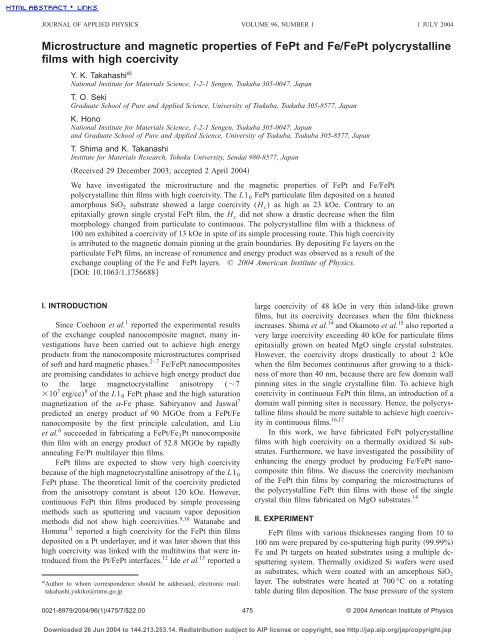
JOURNAL OF APPLIED PHYSICS VOLUME 96, NUMBER 1 1 JULY 2004<strong>Microstructure</strong> <strong>and</strong> <strong>magnetic</strong> <strong>properties</strong> <strong>of</strong> <strong><strong>Fe</strong>Pt</strong> <strong>and</strong> <strong>Fe</strong>Õ<strong><strong>Fe</strong>Pt</strong> polycrystallinefilms with high coercivityY. K. Takahashi a)National Institute for Materials Science, 1-2-1 Sengen, Tsukuba 305-0047, JapanT. O. SekiGraduate School <strong>of</strong> Pure <strong>and</strong> Applied Science, University <strong>of</strong> Tsukuba, Tsukuba 305-8577, JapanK. HonoNational Institute for Materials Science, 1-2-1 Sengen, Tsukuba 305-0047, Japan<strong>and</strong> Graduate School <strong>of</strong> Pure <strong>and</strong> Applied Science, University <strong>of</strong> Tsukuba, Tsukuba 305-8577, JapanT. Shima <strong>and</strong> K. TakanashiInstitute for Materials Research, Tohoku University, Sendai 980-8577, JapanReceived 29 December 2003; accepted 2 April 2004We have investigated the microstructure <strong>and</strong> the <strong>magnetic</strong> <strong>properties</strong> <strong>of</strong> <strong><strong>Fe</strong>Pt</strong> <strong>and</strong> <strong>Fe</strong>/<strong><strong>Fe</strong>Pt</strong>polycrystalline thin films with high coercivity. The L1 0 <strong><strong>Fe</strong>Pt</strong> particulate film deposited on a heatedamorphous SiO 2 substrate showed a large coercivity (H c ) as high as 23 kOe. Contrary to anepitaxially grown single crystal <strong><strong>Fe</strong>Pt</strong> film, the H c did not show a drastic decrease when the filmmorphology changed from particulate to continuous. The polycrystalline film with a thickness <strong>of</strong>100 nm exhibited a coercivity <strong>of</strong> 13 kOe in spite <strong>of</strong> its simple processing route. This high coercivityis attributed to the <strong>magnetic</strong> domain pinning at the grain boundaries. By depositing <strong>Fe</strong> layers on theparticulate <strong><strong>Fe</strong>Pt</strong> films, an increase <strong>of</strong> remanence <strong>and</strong> energy product was observed as a result <strong>of</strong> theexchange coupling <strong>of</strong> the <strong>Fe</strong> <strong>and</strong> <strong><strong>Fe</strong>Pt</strong> layers. © 2004 American Institute <strong>of</strong> Physics.DOI: 10.1063/1.1756688I. INTRODUCTIONSince Coehoon et al. 1 reported the experimental results<strong>of</strong> the exchange coupled nanocomposite magnet, many investigationshave been carried out to achieve high energyproducts from the nanocomposite microstructures comprised<strong>of</strong> s<strong>of</strong>t <strong>and</strong> hard <strong>magnetic</strong> phases. 2–7 <strong>Fe</strong>/<strong><strong>Fe</strong>Pt</strong> nanocompositesare promising c<strong>and</strong>idates to achieve high energy product dueto the large magnetocrystalline anisotropy (710 7 erg/cc) 8 <strong>of</strong> the L1 0 <strong><strong>Fe</strong>Pt</strong> phase <strong>and</strong> the high saturationmagnetization <strong>of</strong> the -<strong>Fe</strong> phase. Sabiryanov <strong>and</strong> Jaswal 7predicted an energy product <strong>of</strong> 90 MGOe from a <strong><strong>Fe</strong>Pt</strong>/<strong>Fe</strong>nanocomposite by the first principle calculation, <strong>and</strong> Liuet al. 6 succeeded in fabricating a <strong><strong>Fe</strong>Pt</strong>/<strong>Fe</strong> 3 Pt nanocompositethin film with an energy product <strong>of</strong> 52.8 MGOe by rapidlyannealing <strong>Fe</strong>/Pt multilayer thin films.<strong><strong>Fe</strong>Pt</strong> films are expected to show very high coercivitybecause <strong>of</strong> the high magnetocrystalline anisotropy <strong>of</strong> the L1 0<strong><strong>Fe</strong>Pt</strong> phase. The theoretical limit <strong>of</strong> the coercivity predictedfrom the anisotropy constant is about 120 kOe. However,continuous <strong><strong>Fe</strong>Pt</strong> thin films produced by simple processingmethods such as sputtering <strong>and</strong> vacuum vapor depositionmethods did not show high coercivities. 9,10 Watanabe <strong>and</strong>Homma 11 reported a high coercivity for the <strong><strong>Fe</strong>Pt</strong> thin filmsdeposited on a Pt underlayer, <strong>and</strong> it was later shown that thishigh coercivity was linked with the multitwins that were introducedfrom the Pt/<strong><strong>Fe</strong>Pt</strong> interfaces. 12 Ide et al. 13 reported aa Author to whom correspondence should be addressed; electronic mail:takahashi.yukiko@nims.go.jplarge coercivity <strong>of</strong> 48 kOe in very thin isl<strong>and</strong>-like grownfilms, but its coercivity decreases when the film thicknessincreases. Shima et al. 14 <strong>and</strong> Okamoto et al. 15 also reported avery large coercivity exceeding 40 kOe for particulate filmsepitaxially grown on heated MgO single crystal substrates.However, the coercivity drops drastically to about 2 kOewhen the film becomes continuous after growing to a thickness<strong>of</strong> more than 40 nm, because there are few domain wallpinning sites in the single crystalline film. To achieve highcoercivity in continuous <strong><strong>Fe</strong>Pt</strong> thin films, an introduction <strong>of</strong> adomain wall pinning sites is necessary. Hence, the polycrystallinefilms should be more suitable to achieve high coercivityin continuous films. 16,17In this work, we have fabricated <strong><strong>Fe</strong>Pt</strong> polycrystallinefilms with high coercivity on a thermally oxidized Si substrates.Furthermore, we have investigated the possibility <strong>of</strong>enhancing the energy product by producing <strong>Fe</strong>/<strong><strong>Fe</strong>Pt</strong> nanocompositethin films. We discuss the coercivity mechanism<strong>of</strong> the <strong><strong>Fe</strong>Pt</strong> thin films by comparing the microstructures <strong>of</strong>the polycrystalline <strong><strong>Fe</strong>Pt</strong> thin films with those <strong>of</strong> the singlecrystal thin films fabricated on MgO substrates. 14II. EXPERIMENT<strong><strong>Fe</strong>Pt</strong> films with various thicknesses ranging from 10 to100 nm were prepared by co-sputtering high purity 99.99%<strong>Fe</strong> <strong>and</strong> Pt targets on heated substrates using a multiple dcsputteringsystem. Thermally oxidized Si wafers were usedas substrates, which were coated with an amorphous SiO 2layer. The substrates were heated at 700 °C on a rotatingtable during film deposition. The base pressure <strong>of</strong> the system0021-8979/2004/96(1)/475/7/$22.00 475© 2004 American Institute <strong>of</strong> PhysicsDownloaded 26 Jun 2004 to 144.213.253.14. Redistribution subject to AIP license or copyright, see http://jap.aip.org/jap/copyright.jsp
476 J. Appl. Phys., Vol. 96, No. 1, 1 July 2004 Takahashi et al.FIG. 1. XRD patterns for various thicknesses <strong>of</strong> <strong><strong>Fe</strong>Pt</strong> films: 10 nm a, 30nm b, 38nmc, <strong>and</strong> 100 nm d.was 6.010 7 Pa, <strong>and</strong> a high-purity argon <strong>of</strong> 0.1 Pa wasflown during sputtering. The growth rate <strong>of</strong> <strong><strong>Fe</strong>Pt</strong> was controlledto 0.10 nm/s <strong>and</strong> the nominal thickness was evaluatedbased on the sputtering time. To produce <strong>Fe</strong>/<strong><strong>Fe</strong>Pt</strong> nanocomposites,<strong>Fe</strong> layers <strong>of</strong> 20%, 40%, <strong>and</strong> 60% <strong>of</strong> <strong><strong>Fe</strong>Pt</strong> thicknesswere deposited on the <strong><strong>Fe</strong>Pt</strong> film at room temperature. Thefilm structures were characterized by x-ray diffractionXRD <strong>and</strong> transmission electron microscopy TEM. Thecompositions <strong>of</strong> the <strong><strong>Fe</strong>Pt</strong> estimated by energy dispersivex-ray spectroscopy were about <strong>Fe</strong> 50 Pt 50 for all the films. The<strong>magnetic</strong> <strong>properties</strong> <strong>of</strong> the films were examined by a superconductingquantum interference device magnetometer.III. RESULTSA. <strong><strong>Fe</strong>Pt</strong> filmFigure 1 shows x-ray diffraction patterns for the <strong><strong>Fe</strong>Pt</strong>films with various thicknesses, t10 nm a, 30nmb, 38nm c, <strong>and</strong> 100 nm d. Superlattice diffraction lines <strong>of</strong>001 <strong>and</strong> 112 are clearly observed around 224° <strong>and</strong>60°, respectively. All the films are ordered to the L1 0 structurein the as-deposited state. The other unlabeled sharppeaks are due to the Si substrate. The relative integratedintensities <strong>of</strong> 001 <strong>and</strong> 111 indicates that all the films havea weak preferred orientation to 001 in the perpendiculardirection to the film plane.Figure 2 shows TEM bright field images <strong>of</strong> the <strong><strong>Fe</strong>Pt</strong>films with various thicknesses. The inset selected area electrondiffraction SAED patterns show that all the films are inthe L1 0 ordered state, because the superlattice diffractionrings <strong>of</strong> 001 <strong>and</strong> 110 are clearly observed as indicated bythe arrows. The average particle size <strong>of</strong> the 10 nm thick filmis about 50 nm. The <strong><strong>Fe</strong>Pt</strong> particles are completely isolatedwith each other. With increasing the film thickness, the averageparticle size increases. The films that are thicker than60 nm have an interconnected network structure. This morphologicalchange is the same as that observed in the <strong><strong>Fe</strong>Pt</strong>film deposited on a MgO 001 single crystal substrate. 14Twins are commonly observed in the particles as indicatedby the arrows. Figure 3 shows a typical 011 nanobeamdiffraction pattern obtained from one <strong>of</strong> the grains that containa twin. The twin was identified as the (111¯) twin, so thisis different from the transformation twins that form when fccdisordered phase transform to the L1 0 tetragonal lattice. 18Hence, these twins are believed to be growth twins whichcommonly occur in the fcc crystals during growth by variousthin film processing. The 111 twins in the L1 0 ordered <strong><strong>Fe</strong>Pt</strong>thin films were also reported by Hong et al. 19Figure 4 shows magnetization curves <strong>of</strong> the <strong><strong>Fe</strong>Pt</strong> filmswith t10 nm a, 20nmb, 30nmc, 38nmd, 60nme, <strong>and</strong> 100 nm f. The filled <strong>and</strong> open circles show themagnetization curves in the perpendicular <strong>and</strong> in-plane directionsto the film, respectively. The magnetization curves arenot corrected with the demagnetization factors. The filmsthat are thicker than 30 nm show weak perpendicular anisotropydue to the development <strong>of</strong> the 001 preferred orientationduring the film growth. Because <strong>of</strong> the high magnetocrystallineanisotropy <strong>of</strong> the isolated particles, theFIG. 2. TEM images <strong>and</strong> SAED patterns for various thicknesses <strong>of</strong> <strong><strong>Fe</strong>Pt</strong> films: 10 nm a, 20nmb, 30nmc, 38nmd, 60nme, <strong>and</strong> 100 nm f.Downloaded 26 Jun 2004 to 144.213.253.14. Redistribution subject to AIP license or copyright, see http://jap.aip.org/jap/copyright.jsp
J. Appl. Phys., Vol. 96, No. 1, 1 July 2004 Takahashi et al.477FIG. 5. Change <strong>of</strong> H c as a function <strong>of</strong> the film thickness.FIG. 3. 011 nanobeam diffraction pattern obtained from one <strong>of</strong> the grainsthat contains a twin.magnetization curves <strong>of</strong> the films with t10 <strong>and</strong> 20 nm donot saturate even at a <strong>magnetic</strong> field <strong>of</strong> 55 kOe. A largecoercivity (H c ) <strong>of</strong> about 23 kOe was obtained from the 10nm thick film. H c gradually decreases with increasing thefilm thickness, but still shows a high H c <strong>of</strong> about 13 kOe att100 nm. The initial magnetization curves for the 10 nm<strong>and</strong> 20 nm thick films are characteristic <strong>of</strong> the rotation magnetization,because large <strong>magnetic</strong> field is required to magnetizethe particles. On the other h<strong>and</strong>, those for 60 <strong>and</strong> 100nm thick films are characteristic <strong>of</strong> the domain wall displacementbecause the initial magnetization curve indicate that themagnetization progress easily at the low <strong>magnetic</strong> field. Figure5 shows the change <strong>of</strong> H c as a function <strong>of</strong> the filmthickness. The H c <strong>of</strong> the <strong><strong>Fe</strong>Pt</strong> films deposited on MgO001 14 <strong>and</strong> MgO 110 20 single crystal substrates are alsoshown in the same figure. With increasing film thickness, theH c for the films deposited on the SiO 2 substrates decreasesgradually, while the H c for the single crystal films depositedon MgO 001 substrates shows a drastic decrease when thefilm thickness is more than 40 nm. The gradual decrease <strong>of</strong>H c in the polycrystalline film as a function <strong>of</strong> film thicknessis similar to that observed in the <strong><strong>Fe</strong>Pt</strong> film deposited on aMgO 110 substrate. 20B. <strong>Fe</strong>Õ<strong><strong>Fe</strong>Pt</strong> filmTo obtain a higher energy product by making a nanocompositewith a s<strong>of</strong>t phase, <strong>Fe</strong> was deposited on 10 <strong>and</strong> 38nm thick <strong><strong>Fe</strong>Pt</strong> particulate films. Figures 6 <strong>and</strong> 7 show thein-plane <strong>and</strong> cross section TEM bright field images <strong>of</strong>: a<strong><strong>Fe</strong>Pt</strong> 10 nm film, b <strong>Fe</strong> 2 nm/<strong><strong>Fe</strong>Pt</strong> 10 nm, c <strong>Fe</strong> 4 nm/<strong><strong>Fe</strong>Pt</strong>10 nm, <strong>and</strong> d <strong>Fe</strong> 6 nm/<strong><strong>Fe</strong>Pt</strong> 10 nm bilayer films. The <strong>Fe</strong>110 diffraction ring is clearly observed in Fig. 6d. Theplan-view image shows that the film morphology is particu-FIG. 4. Magnetization curves with initial magnetization curve <strong>of</strong> variousthicknesses <strong>of</strong> <strong><strong>Fe</strong>Pt</strong> films. Filled <strong>and</strong> opened circles show the magnetizationcurves in the perpendicular <strong>and</strong> in-plane direction to the film, respectively.FIG. 6. TEM images <strong>and</strong> SAED patterns <strong>of</strong> <strong>Fe</strong>/<strong><strong>Fe</strong>Pt</strong> 10 nm bilayer films.Downloaded 26 Jun 2004 to 144.213.253.14. Redistribution subject to AIP license or copyright, see http://jap.aip.org/jap/copyright.jsp
late for all the bilayer films. The cross-sectional image showsthat the <strong><strong>Fe</strong>Pt</strong> particles had relatively flat surface with nearlythe same thickness. The height <strong>of</strong> the particles increases afterthe deposition <strong>of</strong> the <strong>Fe</strong> layers, <strong>and</strong> their shape becomesround as the thickness <strong>of</strong> <strong>Fe</strong> increases. Figure 8 shows themagnetization curves <strong>of</strong> a <strong><strong>Fe</strong>Pt</strong> 10 nm film, b <strong>Fe</strong> 2 nm/<strong><strong>Fe</strong>Pt</strong> 10 nm, c <strong>Fe</strong> 4 nm/<strong><strong>Fe</strong>Pt</strong> 10 nm, <strong>and</strong> d <strong>Fe</strong> 6 nm/<strong><strong>Fe</strong>Pt</strong>10 nm bilayer films. The magnetization curves are correctedwith the demagnetization factors as shown in Table I fromthe average particle size observed from Figs. 6 <strong>and</strong> 7, assumingthe ellipsoidal shape <strong>of</strong> particles. Their <strong>magnetic</strong> <strong>properties</strong>are summarized in Table II. By depositing the <strong>Fe</strong> layer,the H c decreases drastically. On the other h<strong>and</strong>, the residualmagnetization, M r , increases with the <strong>Fe</strong> thickness. As aresult, the energy product increases with the <strong>Fe</strong> thickness.The highest energy product is about 16.9 MGOe.
J. Appl. Phys., Vol. 96, No. 1, 1 July 2004 Takahashi et al.479TABLE II. Magnetic <strong>properties</strong> <strong>of</strong> <strong>Fe</strong>/<strong><strong>Fe</strong>Pt</strong> 10 nm bilayer films.<strong>Fe</strong>nmH ckOeH ckOeM remu/ccM remu/cc(BH) max MGOe(BH) max MGOe0 22.9 21.1 475 450 12.4 7.62 19.2 18.1 585 438 13.7 6.64 12.1 9.4 680 625 13.8 11.06 9.2 5.5 800 890 15.3 16.9phases, viz., <strong>Fe</strong> s<strong>of</strong>t <strong>magnetic</strong> phase <strong>and</strong> L1 0 <strong><strong>Fe</strong>Pt</strong> hard <strong>magnetic</strong>phase. The in-plane magnetization curve <strong>of</strong> the filmswhose <strong>Fe</strong> layer is thicker than 15.2 nm shows decoupled two<strong>magnetic</strong> phases. One is due to the <strong>Fe</strong> s<strong>of</strong>t <strong>magnetic</strong> phasewhich accounts for the decrease in magnetization at around 0Oe. The other is due to the L1 0 <strong><strong>Fe</strong>Pt</strong> hard <strong>magnetic</strong> phasewhich accounts for the decrease in magnetization in the high<strong>magnetic</strong> field region.IV. DISCUSSIONHigh coercive <strong><strong>Fe</strong>Pt</strong> thin films are fabricated on heatedSiO 2 substrates. While H c <strong>of</strong> the film deposited on a MgO001 substrate shows a drastic decrease by 1 order <strong>of</strong> magnitudewhen the morphology <strong>of</strong> the film changes from particulateto the continuous structure, 14 the change <strong>of</strong> the morphology<strong>of</strong> the films deposited on the SiO 2 substrate does notcause the drastic decrease in coercivity. The <strong><strong>Fe</strong>Pt</strong> films onSiO 2 are polycrystal <strong>and</strong> those on MgO 001 are singlecrystal. 14 The large H c <strong>of</strong> the polycrystalline continuousfilms are caused by the strong pinning <strong>of</strong> the <strong>magnetic</strong> domainwalls at the grain boundaries <strong>and</strong> the twins within thegrains. Since the K u <strong>of</strong> the L1 0 ordered <strong><strong>Fe</strong>Pt</strong> is very large,misorientation <strong>of</strong> the easy axis at the grain boundary <strong>and</strong>FIG. 9. TEM images <strong>and</strong> SAED patterns <strong>of</strong> <strong>Fe</strong>/<strong><strong>Fe</strong>Pt</strong> 38 nm bilayer films.twins will act as domain wall pinning sites. 21 On the otherh<strong>and</strong>, since single crystalline <strong><strong>Fe</strong>Pt</strong> continuous films have neithergrain boundaries nor twins, no pinning sites for <strong>magnetic</strong>domain motion are expected. The gradual decrease incoercivity will be explained by the continuous coarsening <strong>of</strong>the grain size as the films are grown on the heated substrates,by which the number <strong>of</strong> domain wall pinning sites decreases.The change <strong>of</strong> the <strong>magnetic</strong> domain reversal mechanismfrom the rotation mode to the nucleation mode will also ex-FIG. 10. Magnetization curves <strong>of</strong> <strong>Fe</strong>/<strong><strong>Fe</strong>Pt</strong> 38 nm bilayer films. The magnetizationcurves are not corrected by thedemagnetization factors.Downloaded 26 Jun 2004 to 144.213.253.14. Redistribution subject to AIP license or copyright, see http://jap.aip.org/jap/copyright.jsp
plain the gradual decrease <strong>of</strong> the coercivity. If grain size canbe kept small, higher coercivity may be achieved even in thethick films.The critical size <strong>of</strong> a single domain particle with a flatellipsoidal shape, d, is given by 22d 24AK u, 12NM swhere A is the exchange stiffness constant, K u is the uniaxialanisotropy constant, N is the demagnetization factor, <strong>and</strong> M sis the saturation magnetization. For L1 0 <strong><strong>Fe</strong>Pt</strong>, A110 6 erg/cm, 23 K u 710 7 erg/cc, 8 <strong>and</strong> M s1150 emu/cc. 8 In the 10 nm-thick film, N is about 7.81.Substituting the demagnetization factor for Eq. 1, the criticalparticles size <strong>of</strong> the single domain is estimated to beabout 200 nm. In the 10 <strong>and</strong> 20 nm thick films, the particlesize is smaller than the single domain size. Hence, the initialmagnetization curves observed in Figs. 4a <strong>and</strong> 4b are explainedby the rotation mechanism. In 60 <strong>and</strong> 100 nm thickfilms Figs. 4e <strong>and</strong> 4f, the morphology changes to a continuousstructure. The initial magnetization curve is characterizedas the nucleation type, although there are twins <strong>and</strong>grain boundaries which can act as pinning sites for domainwall motion. This is because each <strong>of</strong> the grains can be easilymagnetized by the domain wall displacement from a multipledomain to a single domain state, because there are few pinningsites within the grains. Although the twins within thegrains can act as pinning sites, the number <strong>of</strong> twins alsodecreases with the increase <strong>of</strong> the film thickness.In the 30 <strong>and</strong> 38 nm thick films Figs. 4c <strong>and</strong> 4d, themagnetization increases rapidly at a low <strong>magnetic</strong> field <strong>and</strong>increases slowly at a high <strong>magnetic</strong> field. From the TEMbright field images, the films consist <strong>of</strong> isolated polycrystallineparticles. The initial magnetization at the low <strong>magnetic</strong>field region is due to the nucleation-type magnetizationwithin the crystal grains. At this stage, the orientation <strong>of</strong> themagnetization within the grains will be aligned to the c axis<strong>of</strong> each grain by domain wall displacement within the grains.The second increase <strong>of</strong> the magnetization above 3 kOe isattributed to the rotation magnetization <strong>of</strong> r<strong>and</strong>omly oriented
J. Appl. Phys., Vol. 96, No. 1, 1 July 2004 Takahashi et al.4811 The film morphology changes from a particulate structureto a continuous structure with increasing film thickness.2 The 10 nm thick <strong><strong>Fe</strong>Pt</strong> film shows a high H c such as 23kOe. The H c decreases gradually with an increase in thefilm thickness, not showing a drastic decrease like that inthe single crystalline <strong><strong>Fe</strong>Pt</strong> films deposited on a MgO001 single crystal substrate. High coercivity in thepolycrystalline film is due to the <strong>magnetic</strong> domain pinningat the grain boundaries <strong>and</strong> the twins in the grains.3 Exchange coupled <strong>Fe</strong>/<strong><strong>Fe</strong>Pt</strong> bilayer thin films showed improvedenergy products <strong>of</strong> (BH) max 16.9 MGOe.ACKNOWLEDGMENTSThis work was partly supported by the Special CoordinationFunds for Promoting Science <strong>and</strong> Technology on‘‘Nanohetero Metallic Materials’’ from the Ministry <strong>of</strong> Education,Culture, Sports, Science <strong>and</strong> Technology. One <strong>of</strong> theauthors Y.K.T. acknowledges the Japan Science PromotionSociety for a JSPS fellowship.1 R. Coehoorn, D. B. de Mooiji, <strong>and</strong> C. de Waard, J. Magn. Magn. Mater.80, 1011989.2 E. F. Kneller <strong>and</strong> R. Hawig, IEEE Trans. Magn. 27, 3588 1991.3 R. Fischer, T. Schrefl, H. Kronmüller, <strong>and</strong> J. Filder, J. Magn. Magn. Mater.153, 351996.4 S. Hirosawa, H. Kanekiyo, <strong>and</strong> M. Uehara, J. Appl. Phys. 73, 64881993.5 D. C. Crew, J. Kim, L. H. Lewis, <strong>and</strong> K. Barmak, J. Magn. Magn. Mater.233, 2572001.6 J. P. Liu, C. P. Luo, Y. Liu, <strong>and</strong> D. J. Sellmyer, Appl. Phys. Lett. 72, 4831998.7 R. F. Sabiryanov <strong>and</strong> S. S. Jaswal, J. Magn. Magn. Mater. 177–181, 9891998.8 O. A. Ivanov, L. V. Solina, V. A. Demshima, <strong>and</strong> L. M. Maget, Phys. Met.Metallogr. 35, 811973.9 T. Shima, T. Moriguchi, S. Mitani, <strong>and</strong> K. Takanashi, Appl. Phys. Lett. 80,288 2001.10 Y. K. Takahashi, M. Ohnuma, <strong>and</strong> K. Hono, Jpn. J. Appl. Phys., Part 2 40,L1367 2001.11 M. Watanabe <strong>and</strong> M. Homma, Jpn. J. Appl. Phys., Part 1 35, 12641996.12 M. H. Hong, K. Hono, <strong>and</strong> M. Watanabe, J. Appl. Phys. 84, 44031998.13 Y. Ide, T. Goto, K. Kikuchi, K. Watanabe, J. Onagawa, H. Yoshida, <strong>and</strong> J.M. Cadogan, J. Magn. Magn. Mater. 177–181, 12451998.14 T. Shima, K. Takanashi, Y. K. Takahashi, <strong>and</strong> K. Hono, Appl. Phys. Lett.81, 1050 2002.15 S. Okamoto, O. Kitakami, N. Kikuchi, T. Miyazaki, Y. Shimada, <strong>and</strong> Y. K.Takahashi, Phys. Rev. B 67, 094422 2003.16 C. Kuo, P. C. Kuo, <strong>and</strong> H. Wu, J. Appl. Phys. 85, 2264 1999.17 P. T. L. Minh, N. P. Thuy, N. D. Van, <strong>and</strong> N. T. N. Chan, J. Magn. Magn.Mater. 239, 335 2002.18 Y. Tanaka, N. Kimura, K. Hono, K. Yasuda, <strong>and</strong> T. Sakurai, J. Magn.Magn. Mater. 170, 289 1997.19 M. H. Hong, K. Hono, <strong>and</strong> M. Watanabe, J. Appl. Phys. 84, 44031998.20 T. Shima, T. Seki, K. Takanashi, Y. K. Takahashi, <strong>and</strong> K. Hono, ProceedingsInternational Conference on Magnetism, Rome, Italy, 2003.21 R. C. O’H<strong>and</strong>ley, Modern Magnetic Materials Principles <strong>and</strong> ApplicationsWiley-Interscience, New York.22 G. Q. Li, H. Takahoshi, H. Ito, H. Saito, S. Ishio, T. Shima, <strong>and</strong> K.Takanashi, J. Appl. Phys. 94, 5672 2003.23 S. Okamoto, N. Kikuchi, O. Kitakami, T. Miyazaki, Y. Shimada, <strong>and</strong> K.Fukamichi, Phys. Rev. B 66, 024413 2002.Downloaded 26 Jun 2004 to 144.213.253.14. Redistribution subject to AIP license or copyright, see http://jap.aip.org/jap/copyright.jsp