Hypersonic Airplane Space Tether Orbital ... - Tethers Unlimited
Hypersonic Airplane Space Tether Orbital ... - Tethers Unlimited
Hypersonic Airplane Space Tether Orbital ... - Tethers Unlimited
- No tags were found...

Create successful ePaper yourself
Turn your PDF publications into a flip-book with our unique Google optimized e-Paper software.
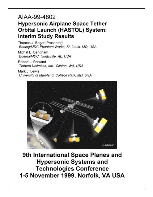
AIAA-99-4802<strong>Hypersonic</strong> <strong>Airplane</strong> <strong>Space</strong> <strong>Tether</strong><strong>Orbital</strong> Launch (HASTOL) System:Interim Study ResultsThomas J. Bogar [Presenter]Boeing/MDC Phantom Works, St. Louis, MO, USAMichal E. BanghamBoeing/MDC, Huntsville, AL, USARobert L. Forward<strong>Tether</strong>s <strong>Unlimited</strong>, Inc., Clinton, WA, USAMark J. LewisUniversity of Maryland, College Park, MD, USA9th International <strong>Space</strong> Planes and<strong>Hypersonic</strong> Systems andTechnologies Conference1-5 November 1999, Norfolk, VA USA
AIAA-99-4802<strong>Hypersonic</strong> <strong>Airplane</strong> <strong>Space</strong> <strong>Tether</strong> <strong>Orbital</strong> Launch (HASTOL) System:Interim Study ResultsDr. Thomas J. Bogar [Presenter], Senior Principal Engineer, <strong>Hypersonic</strong> Design and Applications,Boeing/MDC Phantom Works, P.O. Box 516, St. Louis, MO 63166 USAMichal E. Bangham, Senior Manager Advanced Engineering, Advanced Programs,Boeing/MDC, P.O. Box 240002, Huntsville, AL 35824 USADr. Robert L. Forward, Vice President & Chief Scientist<strong>Tether</strong>s <strong>Unlimited</strong>, Inc. 8114 Pebble Court, Clinton, WA 98236 USADr. Mark J. Lewis, Associate Professor and Director of Center for <strong>Hypersonic</strong> Education and Research,Aerospace Engineering Dept., University of Maryland, College Park, MD 20742 USAABSTRACTThe <strong>Hypersonic</strong> <strong>Airplane</strong> <strong>Space</strong> <strong>Tether</strong> <strong>Orbital</strong> Launch (HASTOL) system is a novel architecture for an Earth-toorbitlaunch system consisting of: a completely reusable airbreathing subsonic-to-hypersonic dual-fuel airplanewhich transports the payload from the ground to some intermediate point in the upper atmosphere; an orbitingspinning space tether system which picks up the payload from the intermediate point and takes it on into orbit; and agrapple assembly for transferring the payload from the hypersonic airplane to the lower end of the space tether. Thesystem is revolutionary in that it minimizes, and perhaps even eliminates, the use of rockets for Earth-to-orbit launchof satellite payloads and even passengers. For the hypersonic airplane portion of the HASTOL system we use anexisting Boeing design for the DF-9, a dual-fuel airbreathing launcher that has benefited from over a million dollarsin NASA/LaRC and Boeing funding during prior study efforts. The DF-9 has a 9Êm (30Êft) long by 3Êm (10Êft)diameter upward-opening central payload bay that can handle payloads up to 14ÊMg (14Êmetric tons or 30,000Êlb).With a full fuel load at takeoff, the hypersonic airplane masses approximately 20 times the payload mass, and candeliver the payload to 100Êkm (330Êkft) altitude at an apogee speed of 3.6Êkm/s (12 kft/s) or approximately MachÊ12.For the space tether portion of the HASTOL system, there are a number of design options, all of which will work,although some options promise better performance. The tethers can be built today using presently availablecommercial fibers. The tethers are long, typically 400 to 1600 km (1300 to 5300 kft) in length. The total mass ofthe space tether plus the <strong>Tether</strong> Central Station typically will be 30-200 times the payloads being handled. Most ofthat mass ratio requirement is driven by the fact that the tether system must mass considerably more than thepayload it is handling, so that, upon pickup of the payload by the tether, the payload will not pull the space tethersystem down into the atmosphere. Thus, the advent in the future of better tether materials with higher strength athigher temperatures will not be used to lower the tether system mass significantly, but instead will be used toincrease the tether safety margins, lifetime, and system performance, by allowing payload pickup at lower altitudesand lower speeds, thus decreasing the performance requirements on the hypersonic airplane portion of the system.INTRODUCTION ÊThe Boeing Company, <strong>Tether</strong>s <strong>Unlimited</strong>, Inc. (TUI),and the University of Maryland, have teamed to studythe feasibility of a completely new concept for movingpayloads and passengers from the surface of the Earthinto low Earth orbit at low cost and low accelerationlevels without the use of rockets as the main source ofpropulsion. Our joint study effort, funded by a $75,000Phase I grant from the NASA Institute for AdvancedConcepts, is halfway through its 6-month term. Thispaper builds upon work reported in a previous paper 1 ,and should be considered an interim report of the studyresults to date, rather than a finished piece of work.Ê Copyright Ó 1999 by TUI, Boeing and University of Maryland.Released to the AIAA to publish in all forms.HASTOL ArchitectureThe <strong>Hypersonic</strong> <strong>Airplane</strong> <strong>Space</strong> <strong>Tether</strong> <strong>Orbital</strong> Launch(HASTOL) system contains three major components: ahypersonic airplane, which will transport the payload ashigh and as fast as possible using air-breathingpropulsion; an orbiting spinning space tether, the lowertip of which will be lowered down and slowed down byone means or another, so as to meet up with thehypersonic airplane; and a grapple assembly at the tip ofthe space tether that will take control of the payload,and with the lift supplied by the space tether, carry thepayload on into orbit. There, after the space tether hasused propellantless propulsion to change its orbit androtation, the payload will be tossed into its desired finaltrajectory. It would be desirable that the HASTOLsystem function in both directions, allowing for return1
of payloads from orbit to the EarthÕs surface. This isnot a firm requirement, however, for a launch-onlyHASTOL system would be useful in itself, sincereturning from orbit is much easier than launching intoorbit. The objective of our ongoing study is to optimizethe combined system of airplane, tether, and grapple inorder to maximize the overall system performance interms of payload mass and delivery rate, whileminimizing the life cycle cost.BackgroundLet us first give some scale to the problem of launchinga payload into space. In order to fly an airbreathingvehicle directly into orbit requires an airplane capable ofreaching horizontal speeds of 7.8Êkm/s (26Êkft/s orapproximately Mach 25) at 150Êkm (490Êkft) altitude oran orbital radius of 6530Êkm (21,400Êkft). Designs existfor hypersonic airplanes capable of level flight at3.1Êkm/s (10Êkft/s or approximately Mach 10), andconcepts exist for faster planes of Mach 12.5 andhigher, but the difficulty of making and operating thehypersonic airplane rises rapidly with increasing Machnumber.There is another scale to the problem of putting thingsinto orbit. Since space starts at about 100Êkm up, mostpeople think that to get into space only involves 100 to200Êkm worth of travel. What they fail to realize is thatevery rocket launched into orbit to date has had to travelthousands of kilometers down range to attain thenecessary 7.8Êkm/s orbital speed. Since the distance Dthat must be traveled at constant acceleration a to reacha final velocity V is D=V 2 /2a, to reach an orbitalvelocity of 7.8Êkm/s at an acceleration of one gee(a=9.8Êm/s), requires covering a distance of 3100Êkm.Similar scaling laws apply to space tethers. If aspinning space tether is to produce a change in velocityof a third of orbital speed, or 2.6Êkm/s, then the tetherlength L for a one gee acceleration at the tether tip needsto be of order L=V 2 /a=690Êkm. As will be illustrated inthe following section on HASTOL <strong>Space</strong> <strong>Tether</strong>Concepts, there are many designs for space tethersystems which can lower a payload grapple assemblyinto the upper atmosphere at grapple speeds with respectto the EarthÕs atmosphere ranging from 4.65Êkm/s(15Êkft/s or MachÊ15) to 3.1Êkm/s (10Êkft/s or MachÊ10)and lower, but the difficulty of operating the spacetether rises rapidly with decreasing grapple speed. Weare quite sure that the bridge between air and space canbe crossed by using the right combination of hypersonicairplane and orbiting space tether. Finding thatoptimum combination is the objective of our study.HYPERSONIC AIRPLANEThe technology for the hypersonic airplane portion ofthe HASTOL system is being developed by Boeing andothers elsewhere and is not part of the HASTOL effort.However, vehicle performance, flight trajectoryrequirements, and operational aspects peculiar to tetherrendezvous and payload transfer in support ofdevelopment and optimization of the HASTOL systemare, and form a major portion of the hypersonic airplaneportion of the HASTOL team effort. The hypersonicvehicle portion of the HASTOL effort will start with anexisting design 2 for the DF-9 (See Fig. 1), a multi-role,hypersonic aircraft developed by Boeing for NASALaRC. The DF-9 can perform both cruise and spacelaunch missions. The vehicle is designed to operatefrom existing runways and incorporates a low-speedpropulsion system based on JP fueled, Air-coreenhancedTurbo Ramjets (AceTRs) for operations up toMachÊ4.5. Above Mach 4.5 a slush-hydrogen-fueledram/scram system powers the vehicle. While the designis optimized for long range cruise at MachÊ10, thevehicle can also perform Òpop-upÓ-type launches ofsatellites, and incorporates a 3Êm (10-ft) diameter, 9Êm(30Êft) long payload bay for that purpose. The vehicledesign does incorporate a linear rocket to provide thrustat altitudes where the airbreathing systems areineffective. One important objective of the study willbe to identify HASTOL scenarios where the rocket isnot needed.Tank 1 (SH 2)PayloadTank 4 (JP-7)LOX (Below)MLGLooking AftRamjet/ScramjetHighly Integrated2-D InletAceTRs(Internal)Tank 2 (SH 2)Tank 5LTank 3 (SH 2)(SH 2)Crew StationTank 6 (SH 2)NLGPayloadTank 7(SH 2)Linear RocketHighly IntegratedSERNAir Core EnhancedTurboramjets (AceTR)Ramjet/ScramjetFig. 1 - DF-9 Dual-Fuel Aerospaceplane2GP94070004.ppt
Our initial assessment of the application of thisparticular vehicle design for accomplishing theHASTOL concept indicates that at the probable 80 to100Êkm rendezvous altitude, the dynamic pressure andtherefore the combustor pressure will be too low forcontinuous cruise operation using current air-breathinghypersonic engine concepts. However, a 100Êkm(330Êkft) rendezvous altitude was found to be readilyattainable using a Òpop-upÓ maneuver as shown inFig.Ê2. This maneuver would allow the safe staging ofminimally streamlined payloads, or payload/upper-stagecombinations, at conditions where the velocity providedby the hypersonic aircraft could be maximized and theperformance of the upper stage optimized. The currentdesign shown in Fig.Ê1 is capable of carrying a30,000Êlb. (14ÊMg or 14 metric ton) combination upperstage and payload to speeds of approximately 3.6Êkm/s(12Êft/s or MachÊ12) at altitudes as high as 100Êkm(330Êkft).Apogee:Altitude 100 kmSpeed 3600 m/sPoweredClimbBallisticTrajectoryto <strong>Tether</strong>RendezvousUnpoweredDescentTanker RendezvousInflight RefuelingFig. 2 - Vehicle Pop-Up To <strong>Tether</strong> RendezvousDuring the future efforts of this continuing study, theexisting hypersonic airplane design will be modified, asrequired, to perform HASTOL type missions and themodifications incorporated into its performancesimulation model. The results of the hypersonic vehicletrade study will be incorporated in the overall HASTOLsystem assessment. Two principal variant types will beassessed. In the first, the aircraft will rendezvous withthe grapple assembly. This variant will be modified, asrequired, for each applicable HASTOL concept and itsrendezvous geometry. In order to operate in theseHASTOL modes it will be necessary to resize theexisting auxiliary rocket engines and their propellantvolumes for increased altitude and velocity. Anenhanced reaction control system with 6-axis capability(including limited trajectory control) will also berequired in lieu of the current 3-axis (attitude only)system.A different variant that will also be studied, will havethe hypersonic airplane carry the payload to anintermediate condition. From there a small rocket upperstage will carry the payload to the rendezvous with thegrapple. This approach will require fewer systemmodifications, but will have less payload capability at aparticular size due to the mass required by the rocketupper stage. Both variants will then be used to evaluatethe concept through several trade studies and optimizedwith the tether and grapple studies.HASTOL SPACE TETHER CONCEPTSThere are many ways of designing the orbiting spinningspace tether component of the HASTOL system. Thesix different space tether system concepts initiallystudied were the: HyperSkyhook, Rotovator,CardioRotovator, CAS<strong>Tether</strong>/LIF<strong>Tether</strong>, TillotsonTwo-Tier <strong>Tether</strong>, and HARGSTOL. In our initialanalyses of each concept, we assumed that the tethersystem would have a <strong>Tether</strong> Central Station (TCS) thatwas many times more massive that the tether or thepayloads being handled. This was assumed so that thecenter-of-mass (CM) of the tether system was at theTCS. In reality, the TCS will have a finite mass, andthe CM of the tether system will not be exactly at theTCS. These corrections will be taken into account inlater, more detailed, tether system design studies.Although the tether mass will usually be less than theTCS mass, we do not want to ignore the tether massentirely. So, for each of the following concepts we haveestimated the mass of the tether alone, using the data wehave for the tensile strength and density of high strengthmaterials that are presently available in commercialquantities. If the mass of the tether starts to exceed 200times the mass of the payload, then that is an indicationthe particular scenario being considered is notengineeringly feasible using presently availablematerials, although the application might becomefeasible in the near future as better materials becomeavailable with higher tensile strengths at higheroperational temperatures.As we shall see later, presently available commercialmaterials will suffice to make the HASTOL conceptwork. Just a modest improvement by a factor of twoover present-day materials in the ratio of the tensilestrength to the density will lower the ratio of the tethermass to the payload mass to the point to where they areno longer a significant factor in the commercialfeasibility of the concept. The primary message wewant to leave with the Reader is: "We don't need magicmaterials like 'Buckminster-Fuller-carbon-nanotubes' tomake the space tether for a HASTOL system. Presentdaymaterials will do."3
HyperSkyhookIn 1995 Zubrin proposed 3 the Ò<strong>Hypersonic</strong> SkyhookÓ asa solution to the mismatch between the attainableatmospheric speeds of a hypersonic airplane and theorbital speeds of space tethers. Since the orbital speedof the space tether decreases with increasing altitude ofthe tether system center-of-mass, he proposed the use ofvery long non-spinning tethers or ÒskyhooksÓ reachingdown from very high altitudes. His analysis showedthat because a hanging tether must be tapered to supportits lower end in the gravitational field of the Earth,achieving a HyperSkyhook tether tip rendezvous with a5.0Êkm/s (16Êkft/s or MachÊ16) airplane would require aHyperSkyhook tether mass of 25 times the payloadmass. Trying to lower the tether tip speed to 4.0Êkm/s(13Êkft/s or MachÊ13) would require a HyperSkyhooktether mass greater than 200 times the payload mass.Unless a major breakthrough occurs in high strengthtether materials, such as the commercial development ofcarbon nanotube fibers, it does not seem possible topush the non-spinning tether HyperSkyhook conceptdown to speeds of 3.1Êkm/s (10Êkft/s or MachÊ10).RotovatorªThe standard method of attaining a low tether tipvelocity is to use a rapidly spinning tether, orRotovatorª. The Rotovator concept was invented in1967 by Artsutanov and reinvented by Moravec in1977, who did the first thorough analysis 4 of it. Sincethe Rotovator must reach down from orbital altitudesinto the upper atmosphere to match speeds with thehypersonic airplane, the length of the tether and theorbital altitude are necessarily interrelated, with theorbital altitude of the tether center-of-mass (CM) beingthe length of the tether plus a nominal 100 km for thethickness of the atmosphere. The longer the tether, thehigher the orbital altitude and the slower the velocity ofthe tether system CM.Rotovatorª <strong>Tether</strong> Mass: The mass of a rapidlyspinning tether in free space is determined primarily bythe tip speed of the tether, not the tether length or thetether tip acceleration. The basic equation for the ratioof the mass M T of one arm of a spinning tether to themass M P of the payload plus grapple on the end of thetether arm, was derived by Moravec in 1978 in anunpublished paper, based on a previously publishedpaper 4 , and is:MMTP=æ V öTp ç ÷è V øWhere the error functionCéæV öTexpêç÷ëêè VCøù æ V öTú erfç÷ûúè VCø2(1)3 52 é z zerf()= z êz- +ë ´ ´ - ù... (2)p 1! 3 2!5úûvaries from erf(0)=0 to erf(>3)=1.0, while erf(1)=0.843,V T is the tether tip speed, and V C =(2U/Fd) 1/2 is themaximum tip speed of an untapered tether, where U isthe ultimate tensile strength of the tether material, d isits density, and F>1 is an engineering safety factorderating the ÒultimateÓ tensile strength to a saferÒpracticalÓ tensile strength. EquationÊ(1) showsspecifically that the mass ratio of a spinning tether is afunction of the ratio of the tether tip speed to thecharacteristic velocity (V T /V C ) only, and to first orderdoes not depend on the tether tip acceleration or thelength of the tether. The exponential growth in the massratio with the square of the velocity ratio seen in Eq.Ê(1)means that attempting to achieve tip velocitiessignificantly higher than the characteristic velocity ofthe material rapidly leads to unfeasible mass ratios.EquationÊ(1), however, is for spinning tethers in deepspace, and does not include gravity gradient forces,which can be significant for long tethers that areoperating close to the Earth.The mass ratio of a long tether near the Earth willdepend not only on the tip velocity of the tether, but alsothe length of the tether and the gravitational accelerationon the tip of the tether. 5-7 This will be true for most ofthe tether systems being considered for the HASTOLarchitecture. There is no simple analytical equation thattakes these gravity gradient forces into account, and themass ratio needs to be numerically integrated for eachcase. Thus, we have used a numerical integrationprogram to generate a table of tether mass ratios forRotovator tethers of various lengths L, spinning atvarious tip speeds V T , with the center of mass of thetether at the orbital radius R O =R E +h+L, and moving at acircular orbit velocity of V O =(GM E /R O ) 1/2, , whereh=100Êkm is the nominal payload pickup altitude,R E =6378Êkm is the radius and M E =5.98x10 24 Êkg is themass of the Earth, and the gravitational constantG=6.67x10 Ð11 Êm 3 /kg-s 2 . The lower end of the orbiting,spinning tether then reaches down into the atmosphereto match speeds with a hypersonic airplane moving at ahypersonic velocity V H =V O ÐV T Ð470Êm/s, where 470Êm/sis the velocity through inertial space of the atmosphereat 100Êkm altitude at the equator of the rotating Earth.We found that spinning tethers that were very short hada lower orbital altitude and therefore higher orbitalvelocity, so they needed a higher tip velocity to matchspeeds with a hypersonic airplane moving at a givenhypersonic velocity. Thus, their mass ratio increasedexponentially as the square of the velocity because ofEq. (1). We also found that tethers that were very long4
were orbiting more slowly, and thus needed less tipvelocity, but because the gravity gradient forces on thetether increased with tether length, the mass ratioincreased because of the increased gravity force. Aftera lengthy search through the parameter space, we foundthat there was a broad minimum in the mass ratio thatoccurred when the tether length and the tether tipvelocity were such that the centrifugal acceleration atthe tether tip was approximately 16Êm/s 2 (52Êft/s 2 or1.6Êgees).Idealized Rotovatorª Results: The results of our firstcut analysis are summarized in TableÊ1. It should beemphasized that in generating TableÊ1 we have madetwo highly idealistic assumptions. First, we assumedthat the <strong>Tether</strong> Central Station is much more massivethan the tether. If this is not true, then the tether massratios given in TableÊ1 could rise by up to a factor of 2.The factor of 2 would be the case where there is no TCSat all, and the counterbalance to the tether arm is anequally massive arm stretching out in the oppositedirection from the CM. Second, we assumed that weare dropping off a payload at the same time (or nearlythe same time) as we are picking up a payload. Thisassumption produces the ideal result that the load on thetether does not change, the CM of the tether does notchange, and the orbit of the CM of the total tetherfacility around the Earth does not change.In prior studies of systems for picking up payloads fromlow Earth orbits and tossing them to the Moon 6 andMars 7 , we showed that practical spinning tether systemscould be designed without using any of the above idealassumptions, that were capable of carrying out thosedifficult payload pickup and toss tasks while massingless than 30 times the payloads being thrown. As wemove further into our HASTOL studies, we will gothrough the same procedure of replacing these idealisticfirst cut tether system designs with progressively morerealistic designs.For the calculation of the tether to payload mass ratio,we used data available for Spectraª 2000, a polymermade by AlliedSignal with an ultimate tensile strengthof 4.0ÊGPa (580,000Êpsi), a specific density of 0.97, anda derated (safety factor of F=2) characteristic velocity of2030Êm/s (6660Êft/s). This material, along with others,is discussed in more detail later in the paper.In Table 1, the column labeled '2x' is for a futurematerial (Spectraª X000?) that has twice the tensilestrength to density ratio of presently available Spectraª2000, while the column '10x' is a "placecard" for somefar future material (derated carbon nanotubes?) that hasten times the ratio of tensile strength to density of thepresently available Spectraª 2000 fiber.From looking at TableÊ1, we can see that the use ofpresent-day Spectraª in a HASTOL system will enablethe Rotovator system to work down to about 3.4Êkm/s(Mach 11) without the tether becoming too heavy.Column '2x' indicates that it only takes a smallimprovement in tether materials for the Rotovatorconcept to work down to 3100Êm/s (Mach 10). Column'10x' indicates that carbon nanotubes would be"overkill" as far as the Rotovator concept is concerned.We don't need carbon nanotubes to make a HASTOLsystem, as we will need to retain some amount of massin the tether in order to keep the tether system itselffrom being pulled out of orbit by the payload!Table 1 - Minimum Mass Ratio Rotovatorª <strong>Tether</strong> Parameters for HASTOL Application<strong>Tether</strong>Length<strong>Orbital</strong>Radius<strong>Orbital</strong>VelocityTipVelocity<strong>Hypersonic</strong> <strong>Airplane</strong>Velocity<strong>Tether</strong> to PayloadMass RatioL R O V O V T V H = V O -V T -470 m/s M T /M P(km) (km) (m/s) (m/s) (m/s) Mach Spectraª 2x 10x400 6878 7614 2494 4650 15.0 10.4 2.4 0.37500 6978 7559 2749 4340 14.0 16.7 4.2 0.56600 7078 7506 3006 4030 13.0 27.1 5.9 0.65700 7178 7453 3263 3720 12.0 44.0 8.2 0.73800 7278 7402 3522 3410 11.0 71.8 11.6 0.90900 7378 7352 3782 3100 10.0 117.6 16.3 1.07Realistic Rotovatorª Results: We recently havegenerated some new results where we assumed a morerealistic design for the Rotovatorª Facility and a morerealistic operational scenario. In this analysis, weassumed a payload mass of 15ÊMg (33,000Êlb), grappleassembly mass of 0.5ÊMg, tether length of 600Êkm,pickup altitude of 100Êkm (330Êkft), and pickup velocityof 4.1Êkm/s (13Êkft/s), which requires the hypersonicaircraft to fly at 3.6Êkm/s (12Êkft/s or Mach 12) at theequator so that it can take advantage of the 470Êm/s(1500Êft/s) rotation of the Earth. This more realisticoperational scenario assumed that there would be only apickup of the payload, without a compensating drop-offof a payload. This, in turn, required that the CM of the5
Rotovator Facility be in an initially elliptical orbit withan eccentricity of 0.0062, so that after pickup of thepayload, the Rotovator Facility dropped into an orbitwith a perigee such that the tip of the spinning tether didnot hit the atmosphere.The analysis is still in the process of being optimized,but with the assumption that we use Spectraª 2000material with a safety factor of 2, then the required massof the tether alone was calculated to be approximately91 times the payload mass (about double that inTableÊ1), while the mass of the <strong>Tether</strong> Central Facilityneeded to be 110 times the payload mass, for an overallRotovator Facility mass ratio of 201. If a strongermaterial becomes available, that has twice the strengthto-densityof Spectraª 2000, then an optimizedRotovator Facility with a tether length of 600 km wouldoperate in a slightly more elliptical orbit with aneccentricity of 0.0145. The mass of the tether alonewould now be only 11 times the payload mass, while toavoid the payload from dragging the Rotovator Facilitydown into the atmosphere, the TCS mass would actuallyhave to increase to 120 times the payload mass! Thetotal Rotovator Facility mass would then be 131 timesthe payload mass. We expect that these total massratios will drop as we optimize the system.Although these mass ratios are high, they are notimpractical, considering that the Rotovator Facility canbe used to "build itself" by starting out small, thenpicking up tether and power modules to build up thelength, thickness, and taper of the tether, and picking upsolar power modules to build up the power supplyneeded by the propellantless electrodynamic tetherpropulsion system 6 that maintains the Rotovator Facilityorbital altitude and spin speed. Carroll has shown 5 thattether facilities are capable of pickup up a payload withthe end of a tether, then "tossing" the payload into anorbit where the payload later can rendezvous and dockwith the CM of the facility (somewhat like tossing apeanut into your mouth)!The important point to make about our study results sofar, is that an orbiting spinning space tether built usingexisting space tether materials, and using the simplestexisting tether facility design, can be used to pick up apayload from an existing design for a hypersonicairplane that is capable of taking a payload to an altitudeof 100Êkm (330Êkft) altitude while moving at 3.6Êkm/s(12Êkft/s or Mach 12). Thus, the HASTOL systemcombination of a Spectraª 2000 Rotovatorª and aDF-9 Aeropaceplane is capable of taking payloads fromthe surface of the Earth and putting them into space.The other HASTOL concepts we will discuss later mayprove to be better, but this concept will suffice.CardioRotovatorThe CardioRotovator concept consists of a <strong>Tether</strong>Central Station in an elliptical orbit, with a single longtapered tether. The tether rotation rate is chosen to beexactly twice the orbital period. The phase of therotation is chosen such that when the <strong>Tether</strong> CentralStation is at perigee, or closest to the Earth, the tether ispointing straight up, as is shown in Fig. 3. Then, when<strong>Tether</strong> Central Station is at apogee, or furthest from theEarth, the tether is pointing straight down at the Earth,reaching deep into the atmosphere for the payloadpickup.Fig. 3 - CardioRotovator ConceptAs can be seen in Fig.Ê3, at intermediate points, thetether is pointing away from the Earth and does notpenetrate below the <strong>Tether</strong> Central Station altitudeexcept near the touchdown point below the apogeepoint. The trajectory of the tip of the tether isapproximately heart-shaped, which lead to the name of"CardioRotovator" for the system concept. Unlike thecircular orbit Rotovator system, the tether length and tipvelocity of a CardioRotovator cannot be chosenindependently. Once a particular apogee radius R A ischosen, that determines the length of the tether, sinceL=R A ÐR E +h. Then, once a particular perigee radius R Pis chosen, that, along with the apogee radius, fixes theorbital period P to be:6
ì( )/ï RA+ R üP ïP = p í ýîï 2GM E þï3 1 2The rotational period p of the spinning tether itself isthen also determined, since the design of theCardioRotovator requires that p=P/2. This rotationalperiod, together with the tether length L, thendetermines the tether tip speed as V T =2pL/p=pL/P.In Table 2, we have tabulated some relevant examplesof the CardioRotovator system parameters, assumingthat in all cases the perigee altitude of the <strong>Tether</strong> CentralStation is 500Êkm, which is just outside the International<strong>Space</strong> Station nominal altitude of 400Êkm. With theseassumptions, the CardioRotovator tether tip accelerationlevels were found to between 0.43 and 0.66 gees,(3)acceleration levels easily accommodated by humanpassengers. Again, for TableÊ2, we have assumed anidealistic situation where the TCS has an infinite massand that a payload pickup is compensated by a payloaddrop-off.By comparing Table 1 for the Rotovator systems withTableÊ2 for the CardioRotovator systems, it is seen thatthe CardioRotovator gives somewhat better results thanthe Rotovator. In general, however, the length of theCardioRotovator tether is much longer than the lengthof the Rotovator tether, which leads to greater concernabout collisions of the tether with other objects in space.This concern is partially compensated by the fact thatthe CardioRotovator tether spends most of its time athigh altitudes where there is less traffic.Table 2 - CardioRotovator <strong>Tether</strong> Parameters for HASTOL Application<strong>Tether</strong>Length<strong>Orbital</strong>Radius<strong>Orbital</strong>VelocityTipVelocityTipAccel.<strong>Hypersonic</strong> <strong>Airplane</strong>Velocity<strong>Tether</strong> to PayloadMass RatioL R O V O V T a V H = V O -V T -470 m/s M T /M P(km) (km) (m/s) (m/s) (m/s 2 ) (m/s) Mach Spectra 2x 10x1000 7478 7147 2076 0.43 4601 14.8 10.8 3.1 0.391200 7678 7004 2440 0.50 4094 13.2 22.2 5.2 0.551400 7878 6868 2789 0.56 3608 11.6 44.7 8.4 0.751600 8078 6737 3124 0.61 3143 10.1 87.8 13.4 0.971800 8278 6611 3445 0.66 2695 8.7 168.5 21.0 1.24Two-Stage RotovatorThe Tillotson Two-Tier <strong>Tether</strong> (TTTT or T4) 8 consistsof a long, large, tapered "first stage" spinning tether, atthe end of which is a smaller "second stage" spinningtether as shown in Fig. 4. The T4 is essentially a twostageRotovator. The use of two tiers or two "stages" inthe design of a spinning tether decreases the overallratio of the tether launch system mass to payload mass,in a manner similar to the benefits of the lower massratio obtained when using a two-stage rocket in a rocketlaunch system.Since the ratio of the tether mass to the payload mass ofa spinning tether increases as the exponential of thesquare of the tip velocity (see Eq. 1), large reductions inoverall mass ratio can be obtained by dividing up thetotal tip velocity required into nearly equal amounts. Ina typical HASTOL scenario where a tether tip velocityof 3.6Êkm/s (12Êkft/s) is needed to meet, say, a MachÊ11hypersonic aircraft moving at 3.4Êkm/s (11Êkft/s), thetether mass required might be 80 times the payloadmass. If instead, the first stage tether rotates at a tipspeed of 1.8Êkm/s (6Êkft/s), while the second stage tetheralso rotates at a tip speed of 1.8Êkm/s, the combinedvelocities reach the 3.6Êkm/s needed for the pickup, butthe combined mass of the two tethers could be as littleas 21 times the mass of the payload.In the T4 concept, there will be a <strong>Tether</strong> Central Station(TCS) (assumed to have infinite mass for this first cutanalysis), around which will be spinning a one-arm firststage tether, with an effective radius of rotation aroundthe TCS of R 1 . At the end of the first stage tether willbe a stiff pivot bearing supported at both ends by thesplit end of the first stage tether, as shown in Fig. 4.This pivot bearing will be the central support point forthe spinning second-stage tether, which will have aradius of rotation R 2 . The total length, when bothtethers are aligned along the nadir, will be L=R 1 +R 2 .Since we want the pickup to take place at an altitudeh=100Êkm (330Êkft), this determines the orbital radius ofthe TCS to be R O =R E +h+L, where R E is the radius of theEarth. The orbital velocity is then just V O =(GM E /R O ) 1/2 ,where G is the Newtonian gravitational constant and M Eis the mass of the Earth.7
CAS<strong>Tether</strong>/LIF<strong>Tether</strong>Another concept for the space tether portion of theHASTOL system uses two separate methods foroperating the tether. The Cast Ahead Supersonic <strong>Tether</strong>or CAS<strong>Tether</strong> concept involves "casting" the tetherahead of the <strong>Tether</strong> Central Station and usingaerodynamic drag to slow the tip of the tether down tohypersonic speeds. The Lift Into Freefall <strong>Tether</strong>concept involves arranging for the aerodynamicallyslowed tether to be vertical just as the TCS is passingoverhead. The TCS will then initially "lift" the payloadvertically upwards, then pull it along behind into orbit.The two concepts are illustrated in our previouspublication. 1 We have yet to carry out an analysis ofthis concept, so we will not discuss it further here.HARGSTOLThe final method of accomplishing the HASTOLconcept is to compromise, and allow the partial use of arocket upper stage or a rocket-powered grapple tocomplete the payload transfer between the hypersonicairplane and the grapple assembly at the end of thespace tether. Thus, instead of the HASTOL system, wewill have the HARGSTOL or <strong>Hypersonic</strong> <strong>Airplane</strong>,Rocket Grapple, <strong>Space</strong> <strong>Tether</strong> Orbit Launch system.This concept has a number of possible variations. Thenormal method would be to have the rocket augmentedgrapple on the tip of the tether. The tether systemwould slow the tip down as much as possible using oneof the tether tip slowing techniques, and the airplanewould fly as fast and high as possible, and the rocketsystem on the grapple would make up any speeddifference. The grapple would need to be refueledperiodically. This could be done at each payloadpickup, or there could be periodic pickups of propellanttanks, with the empty tanks added to the <strong>Tether</strong> CentralStation ballast.A variation on this concept would be to have the majorpart of the tether mass be a permanent part of the spacetether system, but the ÒtipÓ of the tether and the rocketgrapple would be carried by the hypersonic airplane. Atsome time interval before the rendezvous time, thegrapple would be separated from the airplane, pullingout the tether, which would be made of material capableof coping with the hypersonic heating and stress. Therocket grapple would then climb in altitude and speed tomeet up with the lower end of the space tether out inspace away from the atmosphere, while the airplanestays in the atmosphere at an optimum cruise altitude.The grapple grabs the end of the tether, the payload ispulled free from the airplane, and lifted into space bythe tether.The ultimate rocket grapple concept would have therocket take the grapple from the hypersonic airplane allthe way to the <strong>Tether</strong> Central Station, pulling out tetherfrom the payload. Since for normal DV requirementsthe tether mass would be much larger than the payloadmass, it is obvious that a better technique would be tomeet the downgoing tether from the <strong>Tether</strong> CentralStation ÒhalfwayÓ. Finding the optimum ratio for thelength of the airplane tether versus the space tetherwould be part of the overall system optimization. Thisconcept, with the rocket grapple coming from theairplane without carrying the payload, would only beusable for taking payloads into orbit. For two-waysystems, it would be necessary to have the rocketgrapple on the end of the space tether, and have therockets on the grapple capable of accelerating both thegrapple and the payload.The most important feature of all the possibleHARGSTOL systems is that we KNOW we can makethem work, no matter how poor the ultimateperformance of the hypersonic airplane and the spacetether. All it requires is that the rocket grapple beloaded with enough propellant to close the velocity gap.Since the mass ratio of the propellant to grapple-pluspayloadis exponential in the grapple DV, and the rocketDV is low because of the DV contributions of both theairplane and tether, the propellant required should below.SPACE TETHER ISSUES 6,9The space tether portion of the HASTOL system has anumber of issues that must be dealt with other than themethod of operation, including surviving damage bymeteorites and space debris, operating at hypersonicspeeds in the upper atmosphere, avoiding collisions withother spacecraft, and safe and reliable operation at lowsystem mass.<strong>Tether</strong> SurvivabilityFor a tether transport system to be economicallyadvantageous, it must be capable of handling frequenttraffic for many years despite degradation due toimpacts by meteorites and space debris. Yet, the tethermass must be minimized to reduce the cost offabricating and launching the tethers. These tworequirements present conflicting demands upon thetether design that make conventional single-line tethersimpractical for the HASTOL application. For a singlelinetether to achieve a high probability of survival formany years, it must be very thick and massive.Fortunately, a low mass survivable tether design exists,called the Hoytetherª, which can balance therequirements of low weight and long life 9 . As shown inFig.Ê5, the Hoytether is an open net structure where theprimary load bearing lines are interlinked by redundantsecondary lines. The secondary lines are designed to beinitially slack, so that the structure will not collapse9
under load. If a primary line breaks, however, thesecondary lines become engaged and take up the load.Note in Fig. 5, that four secondary line segments replaceeach cut primary line segment, so that their crosssectionalarea need only be 0.25 of the primary line areato carry the same load. Typically, however, thesecondary lines are chosen to have a cross-sectional areaof 0.4 to 0.5 of the primary line area, so as to better copewith multiple primary and secondary line cuts in thesame region of the tether. This redundant linkageenables the Hoytetherª structure to redistribute loadsaround primary segments that fail due to meteoritestrikes or material failure. Consequently, the Hoytetherstructure can be loaded at high stress levels, yet achievea high margin of safety.<strong>Tether</strong> System Collision AvoidanceThere are many objects in space, ranging frommicrometeorites to operational spacecraft with10ÐmeterÐlong solar array panels. We can designinterconnected multiple strand open net Hoytetherªstructures that can reliably (>99.9%) survive in spacefor decades despite impacts by objects up to 30Êcm (1Êft)or so in size. Objects larger than one meter will impactall the strands at one time, cutting the tether. Theselarge objects could include operational spacecraft, andthey will also be damaged by the impact. Objects largerthan 30Êcm are all known and tracked by the U.S. <strong>Space</strong>Command. There are about 6000 such objects in lowand medium Earth orbit, of which an estimated 600 willbe operational spacecraft in the 2005 time frame. Foran atmospheric tether application, we have estimatedthat, if no traffic control measures are instituted, a20Êkm long tether in an orbit grazing the upperatmosphere has a 4% chance of being cut by one of the6000 large objects during a one year mission, and an0.4% chance of striking one of the 600 operationalspacecraft. Longer tethers will have proportionatelylarger probabilities. It will therefore be incumbent onthe HASTOL system operators to maintain contact withthe U.S. <strong>Space</strong> Command and keep an accurateinventory of the known large objects. They then need tocontrol the tether system CM orbital altitude and phase,the tether rotation rate and phase, and the tether librationand vibration amplitudes and phases, to insure that thetether system components do not penetrate a volume of"protected space" around these large orbiting objects.<strong>Tether</strong> Safety Factor and System ReliabilityWhen a tension member such as a tether is developed, itis normally designed to operate at a load levelsomewhat lower than the maximum it could supportwithout breaking. This derating provides margin oferror in case of imperfections in the material or theconstruction. Typically, a single line tether is designedto carry a maximum load that is 50% of its breakinglimit. This tether would thus have a "design safetyfactor" of F=1/0.50=2.0. For the Hoytether 9 , we definethe safety factor as the ratio of the maximum loadcapacity of both primary and secondary lines to thedesign stress load S P of the primary lines alone.PrimaryLinesSecondaryLines(initiallyunstressed)0.2 to10's ofmetersFirst Level ofSecondaryLinesRedistributesLoad toAdjacentNodesSeveredPrimaryLineEffects ofDamageLocalizedSecond Levelof SecondaryLinesRedistributesLoad Back toUndamagedPortion ofPrimary Line0.1- 1 metera. b.c.Fig. 5 - The Hoytetherª design and its response to a cut line10
F=[1+(N S A S )/(N P A P )]/S P (6)where N P and N S are the number of primary lines andsecondary lines, and A P and A S are their respectivecross-sectional areas. For a typical tubular Hoytetherªthere are twice as many secondary lines as primary linesso N S =2N P and Eq. (6) reduces to F=[1+2A S /A P ]/S P .For the case where the secondary line area is half theprimary line area or As=0.5Ap and the stress on theprimary lines is 67% of the ultimate tensile strength ofthe material or S P =0.67, then the Hoytetherª safetyfactor would be: F=[1+2(0.5)]/0.67=3. This definitionof the Hoytetherª safety factor provides the samemeasure of the strength-to-weight ratio of the Hoytetherstructure as it does for a single-line tether. However,this definition of the safety factor does not accuratelyrepresent the margin of safety for the Hoytether.Because the Hoytether has redundant links that canreroute stress around parts of the tether that have failed,it is possible to load the Hoytether at a large fraction ofthe capacity of the primary lines (i.e.- small "line safetyfactor") and still have a large margin of safety againstparting.To study the optimization of the Hoytether structure forhigh-load applications, we performed a series ofsimulations of variations of the structure using our"<strong>Space</strong>Net" tether simulation program 6 . The <strong>Space</strong>Netprogram uses a combination of finite-element methodswith a structural relaxation scheme to calculate theeffects of damage to complex 3-D net structures such asthe Hoytether. The results of our analyses indicate thatthe design of an optimal Hoytether depends upon howmuch of its mission duration will be spent under highload. Consequently, there are two classes ofHoytetherª designs, one for tethers that are alwaysunder high load, and one for tethers that are heavilyloaded for brief periods only.Continuous High Load <strong>Tether</strong>: If the tether will beunder high load for most of its mission, then it should bedesigned with secondary lines slack at the expected loadlevel. This will enable the tether lines to remain spreadapart at all times, minimizing the chances of a singleimpactor cutting several lines. For this case, <strong>Space</strong>Netsimulations showed that a near-optimal tether designwould be a cylindrical Hoytether with a large number ofprimary lines (~20) stressed at 75% of their maximumload and with initially-slack secondary lines that eachhave a cross-sectional area 0.4 times that of a primaryline. Simulations showed that splitting the tether up intoa large number of primary lines prevented the stressenergy released by a cut of one of the primary linesfrom overloading neighboring primary lines before thesecondary lines could become taut enough to take up thereleased stress and pass it around the cut primary linesegment to the uncut primary line segments above andbelow the cut segment.. From Eq.Ê(6), such a tether willhave a design safety factor of 2.4. However, theredundant nature of the structure will make theHoytether far more reliable than a single line tether withthe same safety factor. Simulations with the <strong>Space</strong>Netprogram have shown that this tether design canwithstand multiple cuts on a single level. In fact, evenif all of the primary lines on one level are cut (one at atime), the secondary lines will support the load.Intermittent High Load <strong>Tether</strong>: The HASTOL <strong>Space</strong><strong>Tether</strong> facility, however, would likely be loaded at highlevels for only a few hours at a time. Therefore, it ispossible to reduce the tether weight by designing it tohave slack secondary lines at the load level experiencedduring its long "off-duty" periods, but to have thesecondary lines bear a significant portion of the loadduring a brief high-stress operation such as a payloadcatch-and-throw operation. During the high-stressperiod, the loading of the secondary lines will cause thestructure to collapse to a cylindrical tube. Once apayload is released and the stress is reduced, however,the tether lines will spread back apart. If this high-loadperiod is brief, it will only slightly increase the chancesof tether failure due to impact by a large object.Simulations indicate that a 20-primary line Hoytetherwith the secondary line areas 1/4 of the primary linescan be safely loaded to 85% of the primary line capacityduring peak stress operations. The design safety factorof this tether from Eq. (6) is F=1.75. In this paper wewill use a more conservative safety factor of F=2.<strong>Space</strong> <strong>Tether</strong> MaterialsThe space tether used in the HASTOL system willconsist of a long strength member made of a highstrength, low density polymer, with a "hypersonic" tipmade of a high strength at high temperature, atomicoxygenresistant material. Woven into the initial 10 kmof the polymer tether nearest the <strong>Tether</strong> Central Stationwill be an aluminum wire conductor to be used by theHoyt Electrodynamic Force <strong>Tether</strong> (HEFT) propulsionsystem 6 built into the tether and used by the TCS tocontrol the tether system orbit and spin parameters.High Strength Main Member: The two candidatepolymers for the high tensile strength main portion ofthe tether, Spectraª and Zylonª, are both stronger perpound than either steel or Kevlarª polymer fiber.Their "characteristic velocity", defined as the maximumtip speed of an untapered tether, is: V C =(2U/d) 1/2 , whereU is the ultimate tensile strength of the material and d isits density. Spectraª 2000 has a U=4.0ÊGPa,d=970Êkg/m 3 and V C =2872Êm/s, while Zylonª has aU=5.8ÊGPa, d=1560Êkg/m 3 and V C =2727 m/s. Both ofthese materials are commercially available in tonnage11
quantities with reasonable prices and delivery times.These polymer materials are sensitive to attack byatomic oxygen (AO), however, so the portions that getnear the atmosphere would probably be coated with aproprietary AO-resistant resin coating available fromAeroplas.<strong>Hypersonic</strong> Tip: The material for the hypersonic tipwill not only have to withstand attack by atomicoxygen, but maintain a moderately high strength at hightemperatures. We have estimated that the tethertemperature due to air drag heating will range fromroom temperature (300K or 27C) for a tether speedthrough the air of 3 km/s at 120 km altitude, up to ashigh as 2100K (1830C) for a relative speed of 5 km/s at80 km altitude. The candidate materials and theirultimate tensile strength in GPa (gigapascals) as afunction of temperature are summarized in the Table 4.(For reference, 1ÊGPa = 10 9 N/m 2 = 145,000 psi). Toallow a relative comparison of the suitability of thevarious different tether materials for use in variousspinning tether systems, we also included in Table 4 thedensity d and the room temperature "characteristicvelocity" V C =(2U/d) 1/2 of the material, which is themaximum attainable tip speed of an untapered spinningtether made solely of that material. For reference, themelting points of some of the materials in Table 3 are:AlÐ660C, TiÐ1660C, NiÐ1453C, WÐ3410C,Al 2 O 3 Ð2015C, SiCÐ2700C, and SiO 2 Ð1610C.Table 4 - <strong>Tether</strong> Material Tensile Strength (GPa) vs. TemperatureMaterialV C(km/s)Densityd (g/cc)20C300C600C800C1000C1200CSpectra 2000 2.87 0.97 4.0 - - - - -Zylon (PBO) 2.73 1.56 5.8 3.7 - - - -Quartz Glass (SiO 2 ) 1.81 2.20 3.6 3.6 3.6 3.6 3.6 ?S-glass 1.94 2.50 4.7 ? ? ? ? ?Carbon 2.77 1.80 6.9 ? ? ? ? ?Carbon/Ni-coated 2.12 2.68 6.0 ? ? ? ? ?Tyranno (SiTiCO) 1.66 2.55 3.5 3.5 3.5 3.5 3.5 3.5Textron b-SiC 2.19 2.93 7.0 6.6 6.0 5.6 5.2 4.50.72 b-SiC/Ti-coated 1.72 3.37 5.0 4.8 4.3 4.0 3.7 3.2Altex (Al 2 O 3 /SiO 2 ) 1.21 3.30 2.4 2.4 2.4 2.4 2.4 1.5Nextel (a-Al 2 O 3 ) 1.30 3.88 3.3 ? ? ? ? ?0.65 Nextel/Al-coated 0.97 3.40 1.6 1.4 ? ? ? ?Tungsten Wire 0.55 19.35 2.9 2.9 2.9 2.9 2.9 2.9GRAPPLE AND PAYLOAD TRANSFER ISSUES 8In order for successful rendezvous, docking, andtransfer of the payload to occur, some basic functionsmust be performed by one or more of the HASTOLsystem architecture elements, which include the grappleassembly. The following basic functions have beenidentified and the grapple assembly design process mustconsider all of them:· Establishing a known absolute location forrendezvous, capture, and transfer and keeping itupdated· Establishing and updating relative position betweenthe payload and the grapple assembly· Recognizing the defined rendezvous point· Closing the gap to the rendezvous point· Payload/grapple docking· Payload separation from the hypersonic vehicle· Retention of payload on grapple during transferSeveral grapple design requirements, drivers, andconcerns have resulted from or are associated with theidentification of these functions. Rendezvous, docking,and payload transfer will occur at around 100Êkm(330Êkft) altitude in the presently planned HASTOLscenario. The atmosphere is not very dense at thataltitude. There will be significant heating, but not muchdynamic pressure despite the high velocities involved.The grapple assembly will therefore not need to bestreamlined to any great extent, although it will have towithstand significant heating for its short duration in theatmosphere. The amount of heating will depend uponthe exact rendezvous altitude and speed, and the"height" of the upper atmosphere at the time of therendezvous. Later analysis will also show a clearerpicture of the effects of thermal cycling due to multipleatmospheric passages. It will also aid in future materialspecifications.The tethered grapple assembly motion at the point ofcapture must be in-plane with the payload. Control ofeither the grapple assembly or the payload (payloaditself or the hypersonic vehicle) must be possible to12
insure a successful docking. Structural loading of thegrapple assembly must be taken into account forrendezvous as well as for capture impact and transfer ofthe 14ÊMg (14 metric tons or 30,000Êlb) payload. Nodamage should occur to the payload.A conservative assumption is that there will only be onecapture attempt possible per mission. As a result,maximizing the capture opportunity window is agrapple design objective. This assumption has alsoresulted in a requirement for the capture to be asautomated as possible; a Go/No Go decision initiatedprior to the actual capture by ground control or pilot,should there be one, will be included in the grappleassembly design. It is assumed that abort modes will bedefined prior to each HASTOL mission for the specificclient, though efforts are on-going to identify abortmodes that can be built into the system, for instance,establishing the bounds of an "attempt-to-transferwindow," and a "payload out-of-bounds" window.Other grapple design issues deal with the "no damage"to client payload policy and communications issues.The payload's safety during transfer must be insured,which means either the payload must not tumble duringtransfer, or it must be protected so limited tumbling canbe accounted for at no consequence. The potential ofcommunication loss at each phase of the payloadtransfer scenario must also be considered.A preliminary conceptual CAD drawing of one possiblegrapple assembly option for the tether is shown inFig.Ê6. It features a circular "attach ring" at the bottom,which will mate with grapple hooks on the payload.The attach ring is connected to the rest of the end massvia a six-degree-of-freedom, multiple-shock-absorberstrutsuspension cradle. In the suspension cradle, all ofthe members are designed to compress as necessary,should the payload and grapple mechanism contact atsome non-zero speed or some slightly non-tangentialangle. The struts in the suspension cradle will alsoprovide shock-absorber type damping of the resultingmovement of the attach ring relative to the heavier endmass cylindrical structure at the top, which contains atether winch, batteries, the reaction control system andits propellant, and the command, control and guidanceelectronics.The ring and the suspension leg elements would bemade of materials selected to withstand heating from thehypersonic molecular flow at the rendezvous altitude.This eliminates any need for an aerodynamic cone orshroud, which would increase the aerodynamic drag onthe assembly compared to the mostly empty strutstructure presented to the hydrodynamic molecularflow. The "ends up" cylinder of the upper portion of theFig. 6 - Grapple Assembly Concept Drawinggrapple assembly is already aerodynamically stable.Adding a forward-facing conical aerodynamic "shield"to it would not help appreciably.The grapple assembly requires several internal functionsto be successful for this kind of mission, which make itsimilar to grapple assembly concepts developed earlierfor exo-atmospheric transfer of payloads 10 . As a resultof the relatively high rendezvous altitude of 100Êkm(330Êkft), adding aerodynamic "lift" surfaces on thegrapple assembly will not be effective in maneuveringthe grapple toward a rendezvous with the hypersonicaircraft. The cylindrical portion of the grapple assemblywill have a tether winch will allow the grapple assemblyto "leave" its normal position at the end of the tether byletting out tether. The centrifugal force from therotation of the tether can be used to "cast" the grappleassembly in toward the hypersonic vehicle before the<strong>Tether</strong> Central Station arrives overhead. The grappleassembly will have a reaction control system for finecontrol of its position, velocity, and orientation, but tominimize the problem of refueling of the grappleassembly, it will be up to the reaction control system onthe hypersonic aircraft to remove most of the positionand velocity errors during the rendezvous process.The current concept is to fly the decelerating grapplevehicle in so that it approaches the hypersonic airplanefrom above and behind (this holds true for all grapple13
assembly designs considered). The attach ring wouldattach to the payload and pull the payload up to thegrapple. The hypersonic vehicle would then return toground and the grapple assembly, with payload, wouldbe carried into space by the motion of the tether.After the grapple assembly exits the atmosphere, thetime spent in space will be used to cool and conditionthe grapple assembly, and recharge the batteries inpreparation for the next aeropass. When the grappleassembly is not going to be used to capture or deploy apayload for long periods of time, the tether will beshortened by either the grapple tether winch, or one ofthe other winches along the tether, to raise the minimumaltitude of the tether tip and keep the grapple assemblyabove most of the atmosphere.The hypersonic grapple would not use externallymounted solar panel arrays during the aeropass due tothe high aerodynamic forces and heating rates duringthis phase. Two options to supply electrical power tothe grapple assembly have been identified: adeployable/storable photovoltaic array or an electricallyconductive tether. Each would generate the requiredpower, the latter while moving through the earth'smagnetic field, and would store excess energy in thebatteries for use during the aeropass phase.In order to allow for a reliable rendezvous, the grapplevehicle must maintain location and attitude informationand communicate with the hypersonic airplane. Thiscan be done accurately with a differential GPS similarto those systems being developed for landingcommercial aircraft. The approach velocities are toohigh to rely on human pilots on the ground so thesystem will require autonomous rendezvous and capture(AR&C) capabilities. AR&C technologies, such asadvanced sensors for the final approach and rendezvous,are continuing to evolve, and are maturing based onRussian and NASA investments on dockingtechnologies, and more recently, DARPA investmentsin the ASTRO refueling vehicle concept.CONCLUSIONSWe have described a number of alternate systemconfigurations that will allow hypersonic air-breathingairplane technologies to be combined with orbitingspinning space tether technologies to produce a methodof moving payloads from the surface of the Earth intoEarth orbit. The resultant <strong>Hypersonic</strong> <strong>Airplane</strong> <strong>Space</strong><strong>Tether</strong> <strong>Orbital</strong> Launch (HASTOL) system is completelyreusable and has the potential to drastically cut the costof Earth-to-orbit space access. The system isrevolutionary in that it minimizes, and perhaps eveneliminates, the use of rockets for Earth-to-orbit launchof satellite payloads and even passengers.ACKNOWLEDGEMENTSThis work was supported by a contract with the NASAInstitute for Advanced Concepts (NIAC), Dr. RobertCassanova, Director. The authors also acknowledgetechnical contributions from their fellow co-workers,Robert Hoyt of <strong>Tether</strong>s <strong>Unlimited</strong>, Inc.; Donald Johnsonand Joseph Stemler of Boeing/MDC Phantom Works,St. Louis; Benjamin Donahue and Beth Fleming ofBoeing/MDC, Huntsville; Brian Tillotson of BoeingS&CS, Seattle; and student Daniel Stuart Bowman ofthe University of Maryland.REFERENCES1. Robert L. Forward, Thomas J. Bogar, Michal E.Bangham, and Mark J. Lewis, "<strong>Hypersonic</strong><strong>Airplane</strong> <strong>Space</strong> <strong>Tether</strong> <strong>Orbital</strong> Launch (HASTOL)System: Initial Study Results", IAF-99-S.6.05,presented at the 50th International AstronauticalCongress, Amsterdam, The Netherlands, 4-8October 1999.2. L. F. Scuderi and J. L. Hunt, "Mach 10 Dual-RoleVehicle Concept", <strong>Space</strong> Technology andApplications International Forum, Albuquerque,NM, 1-4 February 1999.3. Robert Zubrin, "The <strong>Hypersonic</strong> Skyhook", Journalof the British Interplanetary Society, Vol.Ê48, No.Ê3,pp. 123-128, March 1995.4. Hans Moravec, "A Non-Synchronous <strong>Orbital</strong>Skyhook", Journal of the Astronautical Sciences,Vol.Ê25, No.Ê4, pp. 307-322, 1977.5. J. Carroll, "Preliminary Design for a 1 km/s <strong>Tether</strong>Transport Facility," NASA OAST Third AnnualAdvanced Propulsion Workshop, JPL, Pasadena,CA, 30-31 Jan 1992.6. Robert P. Hoyt and Chauncey Uphoff, "Cislunar<strong>Tether</strong> Transport System", Paper AIAA-99-2690,35th AIAA/ASME/SAE/ASEE Joint PropulsionConference, Los Angeles, CA, 20-24 June 1999.7. Robert L. Forward and Gerry D. Nordley, "Mars-Earth Rapid Interplanetary <strong>Tether</strong> Transport(MERITT) System: I. Initial Feasibility Analysis",Paper AIAA-99-2151, 35th AIAA/ASME/SAE/ASEE Joint Propulsion Conference and Exhibit,Los Angeles, CA, 20-24 June 1999.8. Brian Tillotson, "<strong>Tether</strong> as Upper Stage for Launchto Orbit", AIAA-89-1585-CP, 3rd InternationalConference on <strong>Tether</strong>s in <strong>Space</strong>, May 17-19, 1989.9. Robert P. Hoyt and Robert L. Forward, "FailsafeMultiline Hoytether Lifetimes", Paper AIAA-95-2890, 31st AIAA/ASME/SAE/ASEE JointPropulsion Conference, San Diego, CA, 10-12 July1995.10. M.ÊE.ÊBangham, E.ÊLorenzini, and L.ÊVestal,"<strong>Tether</strong> Transportation System Study", NASA/TP-1998-206959, NASA Marshall <strong>Space</strong> Flight Center,Huntsville, AL, March 1998.14