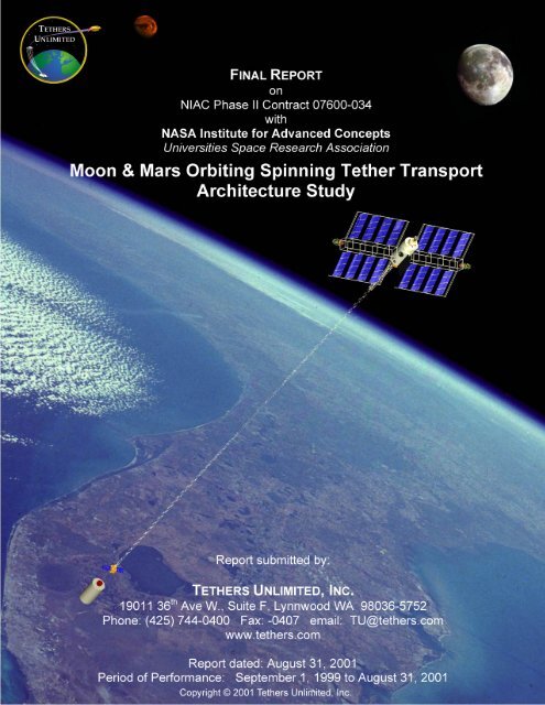
Moon & Mars Orbiting Spinning Tether Transport - Tethers Unlimited
Moon & Mars Orbiting Spinning Tether Transport - Tethers Unlimited
Moon & Mars Orbiting Spinning Tether Transport - Tethers Unlimited

You also want an ePaper? Increase the reach of your titles
YUMPU automatically turns print PDFs into web optimized ePapers that Google loves.
<strong>Tether</strong>s <strong>Unlimited</strong>, Inc.MMOSTT Final ReportTABLE OF CONTENTSI. INTRODUCTION ..........................................................................................................................1II. BACKGROUND .............................................................................................................................2A. MOMENTUM-EXCHANGE TETHERS.................................................................................................2B. ELECTRODYNAMIC REBOOST ...........................................................................................................2C. KEY ADVANTAGES .............................................................................................................................3D. SUMMARY OF PHASE I RESULTS .......................................................................................................4III. PHASE II TECHNICAL OBJECTIVES......................................................................................6IV. SUMMARY OF RESULTS OF THE PHASE II EFFORT........................................................6A. ROADMAP FOR DEVELOPMENT OF A EARTH-MOON-MARS TETHER TRANSPORT SYSTEM ......6B. DESIGN AND SIMULATION OF A TETHER BOOST FACILITY FOR LEO⇒GTO PAYLOADTRANSPORT........................................................................................................................................8C. TETHER FACILITY REBOOST............................................................................................................ 11D. DEVELOPMENT AND SIMULATION OF TETHER RENDEZVOUS METHODS .................................13E. TETHER SYSTEMS FOR INTERPLANETARY TRANSPORT ................................................................15F. µTORQUE:LOW-COST MOMENTUM-EXCHANGE/ELECTRODYNAMIC-PROPULSIONDEMONSTRATION ............................................................................................................................17V. PUBLICATIONS ...........................................................................................................................18VI. CONCLUSIONS ...........................................................................................................................19Appendix A <strong>Tether</strong> Boost Facilities for In-Space <strong>Transport</strong>ation, 2001 NIAC FellowsConference Presentation.Appendix B. “Commercial Development of a <strong>Tether</strong> <strong>Transport</strong> System”, AIAA Paper 2000-3842, Presented at the 36 th Joint Propulsion Conference, Huntsville AL, July 18,2000.Appendix C. “Design and Simulation of a <strong>Tether</strong> Boost Facility for LEO⇒GTO Payload<strong>Transport</strong>”, AIAA Paper 2000-3866, Presented at the 36 th Joint PropulsionConference, Huntsville AL, July 19, 2000.Appendix D. “The Cislunar <strong>Tether</strong> <strong>Transport</strong> System Architecture”, Paper presented at the 2 ndLunar Development Conference, Las Vegas, NV, July 20, 2000.Appendix E. <strong>Tether</strong> Boost Facility Design Study Interim Report, by Boeing/RSS.Appendix F. <strong>Tether</strong> Boost Facility Design Study Final Report, by Boeing/RSS.Appendix G. <strong>Tether</strong> Rendezvous Studies.Appendix H. 2000 NIAC Fellows Conference Presentation.Appendix I. “Rapid Interplanetary <strong>Tether</strong> <strong>Transport</strong> System”. Paper IAF-99-A.5.10,presented at the 50 th International Astronautical Congress, 4-8 Oct 1999,Amsterdam, The Netherlands. This paper summarized the results of the Phase Ieffort.Appendix J. “<strong>Tether</strong> Systems for Satellite Deployment and Disposal”, Paper IAF-00-S.6.04,presented at the 51 st International Astronautical Congress, 2-6 Oct 2000, Rio deJaniero, Brazil.Appendix K. <strong>Tether</strong> Facility Reboost Study.1
<strong>Tether</strong>s <strong>Unlimited</strong>, Inc.MMOSTT Final ReportAppendix L. The µTORQUE Momentum-Exchange <strong>Tether</strong> Experiment, Paper submitted tothe 2002 STAIF Conference.Appendix M. <strong>Tether</strong>Sim : <strong>Tether</strong> <strong>Transport</strong> System Dynamics Verification ThroughSimulation.Appendix N. Momentum-Exchange/Electrodynamic Reboost <strong>Tether</strong> Facility for Deploymentof Microsatellites to GEO and the <strong>Moon</strong>, paper presented at the 2001 STAIFConference, Albuquerque, NM.Appendix O. µSatellite <strong>Tether</strong> Boost Facility, 2001 STAIF Conference presentation ,Albuquerque, NM.Appendix P. Interplanetary <strong>Tether</strong> <strong>Transport</strong> Overview, Paper presented at the 2001 SpaceMechanics Conference.Appendix Q. Application of Synergistic Multipayload Assistance with Rotating <strong>Tether</strong>s(SMART) Concept to Outer Planet Exploration, forum on innovative approachesto outer planetary exploration 2001-2020, 21-23 February 2001, Lunar andPlanetary Institute, Houston, Texas.Appendix R.<strong>Mars</strong>-Earth Rapid Interplanetary <strong>Tether</strong> <strong>Transport</strong> (MERITT) Architecture,Paper presented at 2001 STAIF Conference.2
<strong>Tether</strong>s <strong>Unlimited</strong>, Inc.MMOSTT Final ReportI. INTRODUCTIONMomentum-Exchange/Electrodynamic-Reboost (MXER) <strong>Tether</strong>s can provide a fullyreusable, zero-propellant infrastructure for in-space transportation that will reduce by an orderof magnitude or more the costs of delivering payloads to geostationary orbit, the <strong>Moon</strong>, <strong>Mars</strong>,and other destinations. This Phase II NIAC research program has continued the developmentof a tether-based architecture for in-space propulsion to service transportation needs in theEarth-<strong>Moon</strong>-<strong>Mars</strong> system. This tether architecture will utilize momentum-exchange techniquesand electrodynamic tether propulsion to transport multiple payloads with little or no propellantconsumption. The tether transport architecture is designed to be deployed incrementally, witheach component able to perform a useful revenue-generating mission to help fund thedeployment of the rest of the system. The Phase II effort has focused on the design of the firstcomponent of this architecture, a <strong>Tether</strong> Boost Facility optimized for transferring payloads fromlow Earth orbit (LEO) to geostationary transfer orbit (GTO). The resultant system concept usesa modular design that enables a single launch to deploy a fully-operational tether boost facilitywhich can later be augmented to increase its payload capacity. The first component of the tetherboost facility will be able to toss 2,500 kg payloads from a low-LEO initial orbit to GTO. Thissame facility will also be capable of boosting 1,000 kg payloads to lunar transfer orbit (LTO) orto escape via a lunar swingby. Additional launches of essentially identical modules can increasethe payload capacity of the <strong>Tether</strong> Boost Facility to enable it to boost larger satellites and,eventually, manned spacecraft. This <strong>Tether</strong> Boost Facility can, in turn, be used to deploycomponents of additional tether facilities at the <strong>Moon</strong> and <strong>Mars</strong>, providing an infrastructure forfrequent, low-cost transport between the Earth, the <strong>Moon</strong>, and <strong>Mars</strong>.1
<strong>Tether</strong>s <strong>Unlimited</strong>, Inc.MMOSTT Final ReportII.BACKGROUNDSpace tethers can accomplish propellantless propulsion through two mechanisms, throughmomentum-exchange between two space objects, and through electrodynamic interactions witha planetary magnetic field.A. Momentum-Exchange <strong>Tether</strong>sIn a momentum-exchange tether system, a long, thin, high-strength cable is deployed inorbit and set into rotation around a central body. If the tether facility is placed in an ellipticalorbit and its rotation is timed so that the tether is oriented vertically below the central body andswinging backwards when the facility reaches perigee, then a grapple assembly located at thetether tip can rendezvous with and capture a payload moving in a lower orbit, as illustrated inFigure 1. Half a rotation later, the tether can release the payload, tossing it into a higher energyorbit. This concept is termed a momentum-exchange tether because when the tether picks upand tosses the payload, it transfers some of its orbital energy and momentum to the payload,resulting in a drop in the tether facility’s apogee.Figure 1. Concept of operation of a momentum-exchange tether facility. Orbits are depictedconceptually from the perspective of an observer on the Earth.B. Electrodynamic ReboostIn order for the tether facility to boost multiple payloads, it must have the capability torestore its orbital energy and momentum after each payload transfer operation. If the tetherfacility has a power supply, and a portion of the tether contains conducting wire, then thepower supply can drive current along the tether so as to generate thrust through electrodynamicinteractions with the Earth's magnetic field, as illustrated in Figure 2. By properlycontrolling the tether current during an orbit, the tether facility can reboost itself to its originalorbit. The tether facility essentially serves as a large "orbital energy battery," allowing solarenergy to be converted to orbital energy gradually over a long period of time and then rapidlytransferred to the payload.2
<strong>Tether</strong>s <strong>Unlimited</strong>, Inc.MMOSTT Final Reportthrustcurrentorbitalvelocityappliedvoltagemagneticfield lineFigure 2. Electrodynamic tether thrust generation.C. Key AdvantagesA tether transportation system has several advantages compared to conventional and otheradvanced in-space propulsion systems:1. (Near) Zero Propellant UsageChief among these advantages is the ability to eliminate the need for propellant expenditureto perform payload transfers. Of course, some propellant expenditure will be needed fortrajectory corrections and rendezvous maneuvering, but with proper system design theserequirements will be very small, a few tens of meters per second. The ability to cut severalthousands of meters per second from the ∆V needed to deliver a payload to its destination canenable customers to utilize much smaller launch vehicles than would be required with a rocketonlysystem, greatly reducing total launch costs. For example, launching a 5 metric ton satelliteinto GEO, would require a Delta IVM+ (4,2) launch vehicle using an all-chemical propulsionsystem, at a cost exceeding $90M. Using a tether facility, the payload could instead be launchedinto LEO using a much smaller Dnepr 1 (RS-20) launch vehicle, at 1/7 th the cost of the Deltalaunch.2. Short Transfer TimesA momentum-exchange tether system provides its ∆V to the payload in an essentiallyimpulsive manner. Thus the transfer times in a tether system are very short, comparable torocket-based systems. This can be compared with electric propulsion schemes, which offer lowpropellant usage, but invariably require long transfer times due to their low thrust levels. Theshort transfer times offered by a momentum-exchange tether system can play an important rolein minimizing the lost-revenue time that a commercial satellite venture would have to acceptwhile it waits for its satellite to reach its operational orbit and begin generating revenue if itwere to use a low-thrust, high-Isp electric propulsion upper stage.3. Reusable InfrastructureOnce deployed, a tether boost facility could transfer many, many payloads before requiringreplacement. Thus the recurring costs for payload transport could be reduced to the cost ofoperations. A tether transportation system thus would be somewhat analogous to a terrestrialrailroad or public-transit system, and might achieve comparable cost reductions fortransporting many payloads.4. Fully Testable SystemAnother important but often overlooked advantage of a tether transportation system is thatthe components that perform the actual payload transfer operations can be fully tested in spaceoperations before being used for critical payloads. In conventional rocket systems, enginecomponents and other key elements can be tested on the ground, and many individual units3
<strong>Tether</strong>s <strong>Unlimited</strong>, Inc.MMOSTT Final Reportcan be flown to provide reliability statistics, but to date only the Shuttle has re-used rocketengines, with significant maintenance after each flight. In a tether transportation system, thetether facility could be tested many times with “dummy” payloads – or, better yet, with lowinherent-value payloads such as water or fuel – to build confidence for use on high value ormanned payloads. In addition, "using" a tether does not damage or "wear it out", as long as theloads placed on the tether do not approach the yield point of the tether material. This meansthat the tether used in the operational system is the same tether in nearly the same condition inFigure 3. The Cislunar <strong>Tether</strong> <strong>Transport</strong> System concept.which it underwent strength and reliability testing with the "dummy" payloads.D. Summary of Phase I ResultsIn the Phase I effort, we investigated the feasibility of designing tether transportarchitectures for travel between LEO, the <strong>Moon</strong>, and <strong>Mars</strong>. We developed a design for aCislunar <strong>Tether</strong> <strong>Transport</strong> System that uses one tether in elliptical, equatorial Earth orbit andone tether in low lunar orbit to provide round-trip travel between LEO and the surface of the<strong>Moon</strong>. This design, illustrated in Figure 3, includes considerations for finite tether facilitymasses, the complicated Earth-<strong>Moon</strong> orbital geometry, and the behavior of orbits in the nonidealgravitational potentials of the Earth and <strong>Moon</strong>. We found that, using currently availabletether materials, such a system would require a total mass of less than 28 times the mass of thepayloads it can handle. Because a rocket-based system would require a propellant mass of atleast 16 times the payload mass to perform the same job, the fully-reusable tether system wouldbe competitive from a mass perspective after only two trips, and would provide large costsavings for frequent round-trip travel. Using numerical simulation tools with detailed models4
<strong>Tether</strong>s <strong>Unlimited</strong>, Inc.MMOSTT Final Reportof orbital mechanics and tether dynamics, we verified the feasibility of using this tether systemto transport payloads from LEO to the surface of the moon.We also developed a design for a tether system capable of providing rapid round-triptransport between Earth and <strong>Mars</strong>. The “<strong>Mars</strong>-Earth Rapid Interplanetary <strong>Tether</strong> <strong>Transport</strong>(MERITT) System” would be composed of one rotating tether in highly elliptical Earth orbit andone tether in highly elliptical <strong>Mars</strong> orbit, and could provide short (3-5 month) transfer times inboth directions while eliminating the need for transfer propellant.Figure 4. The <strong>Mars</strong>-Earth Rapid Interplanetary <strong>Tether</strong> <strong>Transport</strong> (MERITT) System Concept.In addition, we developed a concept for using electrodynamic tether propulsion to restorethe orbits of the Earth-orbit tether facilities after each payload boost operation. This design willenable the tether facility to repeatedly boost payloads without requiring propellant expenditureor return traffic. With this innovation, the Cislunar and MERITT systems can be developedincrementally, with the first component capable of boosting multiple payloads to GTO, lunartransfer orbits, and <strong>Mars</strong> injection so that it can earn revenue to fund the deployment of tetherfacilities at the <strong>Moon</strong> and <strong>Mars</strong>.5
<strong>Tether</strong>s <strong>Unlimited</strong>, Inc.MMOSTT Final ReportIII.PHASE II TECHNICAL OBJECTIVESIn the Phase II effort, we sought to build upon the conceptual transportation architecturesdesigned in the Phase I effort by developing a more detailed understanding of the technology,systems, and methods required to implement these transportation systems based upon spacetethers. The technical objectives of the Phase II effort were to:• Design a Momentum-Exchange/Electrodynamic-Reboost <strong>Tether</strong> Boost Facility.• Develop concepts and techniques for tether/payload rendezvous & capture.• Combine and improve the designs of the Cislunar, MERITT, and LEO-GEO systemarchitectures, and explore applications of rotating tethers to other NASA missions.• Design an affordable first-step technology demonstration mission.IV.SUMMARY OF RESULTS OF THE PHASE II EFFORTDuring the course of the Phase II effort, we developed a long-term plan for designing anddeploying a tether transportation system to service traffic between LEO, GEO, the <strong>Moon</strong>, and<strong>Mars</strong>, starting with near-term, low-cost technology demonstration experiments and progressingto operational systems. We then collaborated with the Boeing Company to develop a systemleveldesign for an initial operational <strong>Tether</strong> Boost Facility that would boost commercialsatellites from low-LEO to GTO, and could also boost scientific payloads to the <strong>Moon</strong>. As a partof this design effort, we evaluated the technology readiness level (TRL) of the requiredcomponent technologies. Based upon this TRL evaluation, we identified several key technologyneeds, including systems and methods for payload-tether rendezvous, and systems andmethods for electrodynamic reboost of the tether facility. We then developed concepts forsatisfying these technology needs, and performed proof-of-concept demonstrations usingnumerical simulation. We also investigated the Earth-<strong>Mars</strong> tether transport systems further,evaluating their potential for minimizing transfer times. Finally, we developed a conceptualdesign for a small, low-cost momentum-exchange/electrodynamic-propulsion tether experimentthat would demonstrate many of the needed technologies and techniques.Organization of this ReportThe results of each of the tasks pursued in this Phase II effort are detailed in separatedocuments included in this report as appendices. In the following paragraphs, we summarizethe most important results of these tasks, and give references to the appropriate appendices.Appendix A: “<strong>Tether</strong> Boost Facilities for In-Space <strong>Transport</strong>ation” contains a presentation thatsummarizes the results of the Phase II effort.A. Roadmap for Development of a Earth-<strong>Moon</strong>-<strong>Mars</strong> <strong>Tether</strong> <strong>Transport</strong> SystemThroughout the technical tasks pursued in the Phase II effort, we have sought to map out aplan for addressing the technology needs for a <strong>Tether</strong> <strong>Transport</strong> System and then deploying thesystem in a manner that can be pursued by a commercial venture. In the Phase II efforts, wehave examined the technology readiness level (TRL) of the components and techniques neededfor tether boost facilities. This TRL survey identified several technical challenges that must bemet to enable tether transport systems to be fielded, including development of rapid automatedrendezvous and capture (AR&C) capabilities, techniques for building and controlling the tetherfacilities, and power system technologies able to drive electrodynamic tethers at high powerand voltage levels.In order for a <strong>Tether</strong> <strong>Transport</strong> System to be built successfully, the system architecture mustbe designed so that its development and deployment is commensurate with a viable businessplan. Because the development of a tether transport architecture for transporting frequenttraffic between the Earth, the <strong>Moon</strong>, and <strong>Mars</strong> will require a significant total capital investmentby government and private entities, we have sought to design a system architecture that can be6
<strong>Tether</strong>s <strong>Unlimited</strong>, Inc.MMOSTT Final Reportpropellantless reboost propulsion needed for MXER tether systems. The rendezvous andcapture technologies needed for tether transportation systems can be demonstrated in separate,low-cost experiments, beginning with the “High Altitude <strong>Tether</strong> – Grapple Rendezvous andSecure Pickup” (HAT-GRASP) experiment. The HAT-GRASP experiment would demonstraterendezvous and capture between a tether hanging from a high altitude balloon and a smallpayload launched into a ballistic trajectory by a suborbital rocket. Because the payload wouldbe “coasting” in a 1 g gravity field, the rendezvous situation in this experiment would closelymatch the rendezous scenario in an orbital tether system, but can be done at a relatively lowcost because it does not require a launch into orbit. This technology demonstration would feedinto the “Microsatellite <strong>Tether</strong>ed Orbit-Raising QUalification Experiment” (µTORQUE), whichwould be designed to fly as a secondary payload on a GEO satellite launch, and would useelectrodynamic drag propulsion to spin up a tether and toss a small satellite to a lunar transfer.Combining these technologies for electrodynamic propulsion and tethered rendezvous andcapture would then enable the deployment of a <strong>Tether</strong> Boost Facility designed to boostcommecial satellites to GTO and toss scientific payloads to lunar transfer orbits. This facilitywould be constructed with a modular design, so that its capabilities could be increased toenable it to serve as a space-based “second stage” for Earth-toOrbit launch, and to serve as atransportation hub for Earth-<strong>Moon</strong>-<strong>Mars</strong> traffic.Further details on the incremental development roadmap for building a <strong>Tether</strong> <strong>Transport</strong>System are given in Appendix B, “Commercial Development of a <strong>Tether</strong> <strong>Transport</strong> System.”B. Design and Simulation of a <strong>Tether</strong> Boost Facility for LEO⇒GTO Payload <strong>Transport</strong>The primary focus of the Phase II project was a collaborative effort between <strong>Tether</strong>s<strong>Unlimited</strong>, Inc. and The Boeing Company to develop a design for the first component of a tethertransport architecture, a LEO⇒ GTO <strong>Tether</strong> Boost Facility. This facility will combinemomentum-exchange tether techniques with electrodynamic tether propulsion to provide areusable infrastructure capable of repeatedly boosting payloads from low Earth orbit togeostationary transfer orbit without requiring propellant expenditure.The design effort began by evaluating potential objectives and missions for this systemconcept, and developed a Systems Requirement Document to guide the rest of the design study.The Systems Requirement Document for the LEO⇒GTO <strong>Tether</strong> Boost Facility is presented inAppendix F.The system design has progressed through several iterations, beginning with a facility sizedto handle 5-ton payloads, and then moving to a facility sized to handle 2,500 kg payloadsinitially but designed modularly so that its capacity can be increased in an incremental fashion.The preliminary design is summarized in Appendix E: “<strong>Tether</strong> Boost Facility Design StudyInterim Report”, and the final design is discussed in detail in Appendix F: “<strong>Tether</strong> BoostFacility Design Study Final Report”.8
<strong>Tether</strong>s <strong>Unlimited</strong>, Inc.MMOSTT Final Reportdeployed in a modular, incremental fashion, in which each component can generate revenue tofund the development of the rest of the system, much as the first railroads were developed.Because the largest current commercial market for in-space transportation is the delivery ofcommunications satellites to GEO, the initial <strong>Tether</strong> Boost Facility will be designed primarily toservice traffic of satellites from LEO to GTO. This LEO⇒GTO <strong>Tether</strong> Boost Facility, however,will also be capable of transporting different payloads to other destinations, including LunarTransfer Orbit (LTO). Once the initial facility has been deployed and proven in operation, thesystem capacity could then be built up incrementally by adding more modules. Then,additional tether facilities deployed to handle Earth-to-Orbit Assist, LEOLunar Surfaceround-trip travel, and deployment of manned <strong>Mars</strong> bases.Figure 5. MXER <strong>Tether</strong> Technology Development Roadmap.Figure 5 illustrates the proposed incremental development path for the <strong>Tether</strong> <strong>Transport</strong>System. The development will begin with several low-cost technology development anddemonstration experiments. The first experiment is the ProSEDS mission, a NASA/MSFCexperiment currently scheduled to fly in mid-2002 to demonstrate electrodynamic dragpropulsion using a bare-wire tether. The proposed RETRIEVE experiment will demonstrate avery small (~3.5 kg) electrodynamic tether system that uses current feedback to control thetether dynamics while it deorbits a microsatellite. These two experiments will develop theelectrodynamic propulsion technologies needed to first bring to the commercial market smalloperational electrodynamic tether systems for spacecraft propulsion and deorbit, and then tofield larger tether propulsion systems such as for satellite orbital transfer and reboost of theInternational Space Station. These electrodynamic tether technologies will also provide the7
<strong>Tether</strong>s <strong>Unlimited</strong>, Inc.MMOSTT Final ReportFigure 6. The <strong>Tether</strong> Boost Facility Design concept.1. 5,000 kg Payload <strong>Tether</strong> Boost FacilityThe general trend for GEO communications satellites has been for the satellites to becomelarger and larger with time. Our market projections indicate that a potential “sweet spot” forsystem payload to GTO would be around 5,000 kg. A tether system capable of delivering thissized payload to GTO could serve approximately 80% of the market projected in 2010.Consequently, the initial design effort focused on designing a tether system capable of boosting5,000 kg payloads from 300 km circular LEO to GTO. Because the tether system is a highlyreusable infrastructure, one key to achieving minimum transportation costs will be to maximizeits throughput capacity. By estimating the potential market in 2010, we concluded that areasonable throughput for which to aim would be one payload per month. Thus the systemwas designed to reboost its orbit within 30 days after each payload boost operation. The initialsystem design for this LEO⇒GTO <strong>Tether</strong> Boost Facility is described in Appendix E: “<strong>Tether</strong>Boost Facility Design Study Interim Report”.The potential launch cost savings that a <strong>Tether</strong> Boost Facility could provide to a customercan be illustrated by considering a mission to place a 5,000 kg payload in GTO. To do so usingconventional rocket systems would require a launch vehicle comparable to a Delta IVM+ (4,2),costing upwards of $90M. With a <strong>Tether</strong> Boost Facility capable of picking the payload up fromLEO and tossing it to GTO, the customer could instead use a much smaller launch vehicle suchas a Dnepr 1, with a launch cost of approximately $13M. Even when the operational costs of the9
<strong>Tether</strong>s <strong>Unlimited</strong>, Inc.MMOSTT Final Report<strong>Tether</strong> Boost Facility are added to this figure, this quick comparison indicates that a tethertransport system could reduce the launch costs to the customer by 50%-80%.One of the results of the initial tether boost facility design was that a tether facility capableof tossing 5,000 kg to GTO would require a total on-orbit mass of approximately 50 metric tons.Currently, a launch vehicle capable of placing 50 metric tons in orbit does not exist. Should theneeds of NASA’s HEDS program or other government-led initiatives result in the developmentof the proposed “Magnum” launch rocket, it may become possible to deploy such a tetherfacility in one launch. In the absence of such a beefy rocket, however, a tether boost facility willeither have to be sized for a smaller vehicle, and thus sized for a smaller payload, or will requiremultiple launches and on-orbit assembly.In order for the development of a <strong>Tether</strong> Boost Facility to be affordable for a commercialventure, it will be vital for the facility to be capable of performing a useful, revenue-generatingservice after the first launch. Consequently, our design effort evolved the system concept intoone that would be capable of being launched on a single large launch vehicle expected to be inservice in 2010. This facility would initially have a smaller payload capacity, but would bedesigned in a modular fashion so that its capacity can be increased to service 5,000 kg and largerpayloads:2. 2,500 kg Payload Modular <strong>Tether</strong> Boost FacilityAppendix C, “Design and Simulation of a <strong>Tether</strong> Boost Facility for LEO⇒GTO Payload<strong>Transport</strong>” presents the concept design for a modular <strong>Tether</strong> Boost Facility capable of boosting2,500 kg payloads from LEO to GTO. Using analytical methods, we developed designs for theorbital mechanics and system sizing of the tether facility. The orbital designs were chosen sothat the payload and tether orbits are synchronous, so that the tether will have multipleopportunities to capture a payload with minimal maneuvering requirements. These designsaccount for orbital perturbations due to Earth oblateness. The tether facility power system issized to enable a throughput of one payload every 30 days. The entire tether facility is sized toenable an operational capability to be deployed with a single Delta-IV-H launch. The system isdesigned in a modular fashion so that its capacity can be increased with additional launches.The tether facility can also boost 1000 kg payloads to lunar transfer orbits, and will serve as thefirst building block of an Earth-<strong>Moon</strong>-<strong>Mars</strong> <strong>Tether</strong> <strong>Transport</strong>ation Architecture.Appendix F. : “<strong>Tether</strong> Boost Facility Design Study Final Report” presents the details of thesubcontract effort by Boeing to define a system-level design for this initial operational tetherfacility, and Table 1 presents a summary of the design. The tether facility is sized at 19,891 kg tobe launched into LEO on a single Delta IV-H rocket, and will retain the Delta IV’s upper stagerocket as ballast mass, giving it a total operational mass of 23,358 kg.10
<strong>Tether</strong>s <strong>Unlimited</strong>, Inc.MMOSTT Final ReportTable 1. 2,500 kg to GTO <strong>Tether</strong> Boost Facility Design Summary:• Control Station mass = 13,267 kg (includes 21% mass margin)• Operational mass = 23,358 kg, no margin Control Stationw/Payload Adapter Fixture• GLOW = 19,891 kg with 15% margin, no PAFPower System:• Scarlet-like concentrator PV arrays, 563 square meters• Standard, state-of-the-art PV array drive motors• State-of-the-art power management and distribution except forelectrodynamic tether subsystem• Lithium-ion battery power storage system• 5,410 kg (includes 14% mass growth margin)Communication Subsystem• Downlink communication with ground station(s) andcommunication with Grapple Assembly and PAA (via <strong>Tether</strong>Facility Network)• State-of-the-art, COTS hardware (antennae/transceivers)• Dual redundancy• 4.2 kg (includes 16% mass growth margin)C&DH• State-of-the-art, COTS hardware• Dual redundancy• 29 kg (includes 13% mass growth margin)ADCS/GN&C• 2 Control Moment Gyros (no redundancy), each assumed half size of a Skylab CMG• 2 sun sensors• 2 inertial navigation unit• GPS antennae (3)/tranceivers (2)• 213.8 kg (includes 6% mass margin)Electrodynamic <strong>Tether</strong> Subsystem• Sized for 80 km conductive tether, total length 100 km, 300,000 W, 40 µN/W thrustefficiency• Control Subsystem with 1m diameter, 1.5m long reel, motor, tether guides, powerconversion, FEACs (field emitter array cathodes)• 1,933 kg (includes 36% mass margin)11
<strong>Tether</strong>s <strong>Unlimited</strong>, Inc.MMOSTT Final ReportC. <strong>Tether</strong> Facility ReboostA key factor in the economic competitiveness of a <strong>Tether</strong> Boost Facility will be the frequencywith which the facility can boost payloads. The throughput capacity of a tether facility will bedetermined largely by the time required to restore the facility’s orbit after each payload boostoperation. In this work we have investigated using electrodynamic tether propulsion to reboostthe orbit of the tether without requiring propellant consumption.As with the system design, the investigation of electrodynamic reboost has gone throughseveral iterations. In Appendix K, <strong>Tether</strong> Reboost Study, we present results of our initialanalytical and numerical investigations of the time required to reboost the orbit of the 5,000 kgpayload facility using electrodynamic tether propulsion. We used these results to guide thedesign of the tether facility described in the previous section. The results of the tether systemdesign were then fed back into the simulation effort. In the latter part of Appendix C, “Designand Simulation of a <strong>Tether</strong> Boost Facility for LEO⇒GTO Payload <strong>Transport</strong>” we present morerecent simulation results that use more advanced methods for optimizing the orbital reboost.These latest results indicate that a <strong>Tether</strong> Boost Facility sized for boosting 2,500 kg payloads toGTO once per month will require a solar power system of approximately 100 kW.Semimajor Axis (km)9550950094500 0.5 1 1.5 2 2.5 3Time (days)0.295Eccentricity0.290.285Thrust Efficiency (µN/W)0 0.5 1 1.5 2 2.5 3Time (days)60402000 0.5 1 1.5 2 2.5 3Time (days)Figure 7. Semimajor axis, eccentricity, and thrust efficiency during the first three days of the reboostoperation.12
<strong>Tether</strong>s <strong>Unlimited</strong>, Inc.MMOSTT Final ReportD. Development and Simulation of <strong>Tether</strong> Rendezvous MethodsOf the technology needs identified in the TRL evaluation, the most significant challenge is toenable payloads to successfully and reliably rendezvous with the grapple on a rotating tether.To begin addressing this challenge, we used a numerical simulation that includes models fororbital mechanics and tether dynamics to study the rendezvous between a payload in orbit anda rotating tether facility. In a tether-payload rendezvous, the relative motion between the tethertip and payload is primarily along the local vertical direction. The relative acceleration isconstant, so, from the perspective of the payload, the tether tip descends to the payload, haltsinstantaneously, then accelerates away. We have developed a method for using tetherdeployment to increase the length of time that the payload and grapple are near each other.This method is illustrated in Figure 8. As shown in Figure 9, numerical simulations indicatedthat this tether deployment maneuver can extend the “instantaneous” rendezvous to a windowof tens of seconds, without need for propellant usage. We also studied the effects of the payloadcapture on the tether tension. The simulations indicated that for an ideal rendezvous, tensionwave behavior will cause tension excursions roughly double that of the steady-state loads. Ifthe rendezvous is not ideal, that is, if the tether must be deployed for several seconds while thepayload and tether tip vehicle maneuver to achieve a docking, the resultant tension spikes canfurther increase the peak tether loads. Additional tether deployment maneuvers can help toameliorate the peak tension excursions and damp the longitudinal oscillations.A more detailed discussion of the study of <strong>Tether</strong> Rendezvous Methods is presented inAppendix G.Payload Capture Vehicledescends towards PayloadPCV releasestethered grapplePCV pays out tetherand Payload maneuversto dock with grapplePCV engagestether brake andbegins to lift payloadFigure 8. Schematic of rendezvous method where the Payload Capture Vehicle drops a tethered grappleinto free fall.13
<strong>Tether</strong>s <strong>Unlimited</strong>, Inc.MMOSTT Final ReportFigure 9. Simulation of a rendezvous between a reusable launch vehicle and the grapple end of a tetherboost facility, using the tether deployment method of extending the rendezvous time. The simulation isshown at half-second intervals. (pictures courtesy Boeing)14
<strong>Tether</strong>s <strong>Unlimited</strong>, Inc.MMOSTT Final ReportE. <strong>Tether</strong> Systems for Interplanetary <strong>Transport</strong>Momentum-exchange tether systems may also enable rapid propellantless transport ofpayloads between Earth, <strong>Mars</strong>, and other planets. As a part of this Phase II effort, weinvestigated concepts for using rotating tethers in elliptical orbits around the Earth and <strong>Mars</strong> toprovide a means of tossing payloads between the planets. One concept for such a system is the“<strong>Mars</strong>-Earth Rapid Interplanetary <strong>Tether</strong> <strong>Transport</strong> (MERITT)” System, discussed in AppendixP, “Interplanetary <strong>Tether</strong> <strong>Transport</strong> Overview” and Appendix R, “<strong>Mars</strong>-Earth RapidInterplanetary <strong>Tether</strong> <strong>Transport</strong> (MERITT) Architecture.” In the MERITT architecture, a tetherfacility in a highly elliptical orbit around one planet would pick up payloads when it is nearperiapsis and, when it returns to periapsis, toss them at a velocity sufficient to give the payloada substantial hyperbolic excess velocity. At the destination planet, a second tether systemwould catch the payloads and release them a short time later into a low orbit or a suborbitaltrajectory, as illustrated in Figure 10.Figure 10. Design of the orbital architecture of the <strong>Mars</strong> tether facility in the MERITT system.The system works in both directions and is reusable. Kinetic energy lost by the throwing tetherscan be restored either by catching incoming payloads, by propellantless tether propulsionmethods, and/or high specific impulse propulsion systems. We investigated launch windowlengths and transfer times that a MERITT system could achieve. Figure 11 summarizes theresults of the launch window analysis. As shown in Figure 12, tethers with tip velocities of 3km per second can send payloads to <strong>Mars</strong> in as little as 70 days if aerobraking is used at <strong>Mars</strong> todissipate excess relative velocity and the orbital phasing is favorable. <strong>Tether</strong>-to-tether transferswithout aerobraking may be accomplished in about 110 to 160 days.We also investigated a concept for using momentum exchange tethers to enable missions totwo outer planets to be accomplished by a pair of spacecraft launched by a single rocket. In thisconcept, detailed in Appendix Q: “Application of Synergistic Multipayload Assistance withRotating <strong>Tether</strong>s (SMART) Concept to Outer Planet Exploration,” a tether would be deployedbetween two spacecraft, and the system would then be spun up as it approaches the first targetplanet. When the tethered spacecraft reaches periapse, the tether would release the spacecraft,leaving one payload in orbit around the planet and tossing the other satellite towards its15
<strong>Tether</strong>s <strong>Unlimited</strong>, Inc.MMOSTT Final Reportdestination planet. This method would provide a significant enhancement to the “gravitationalslingshot” delta-V boost that the second spacecraft could obtain from its flyby of the first planet.Figure 11. Launch window analysis for the MERITT Architecture.Figure 12. Transit times for the MERITT System.16
<strong>Tether</strong>s <strong>Unlimited</strong>, Inc.MMOSTT Final ReportF. µTORQUE:Low-Cost Momentum-Exchange/Electrodynamic-Propulsion DemonstrationIn order to begin addressing the key technical challenges in MXER tether systems, we havedeveloped a concept design for a very small momentum-exchange/electrodynamic-propulsiontether system capable of boosting a microsatellite by a ∆V of 0.4 km/s. This “Microsatellite<strong>Tether</strong>ed Orbit Raising QUalification Experiment” (µTORQUE) system is sized to fly, along withits microsatellite payload, as a secondary payload on an upper stage rocket such as theSeaLaunch Block DM 3 rd Stage.The µTORQUE concept is illustrated in Figure 13. The µTORQUE tether system and amicrosatellite payload would be integrated onto a rocket upper stage prior to launch. After thestage releases its primary payload into GTO (1), the µTORQUE system would deploy themicrosatellite from the stage at the end of a high-strength conducting tether (2). The systemwould then use electrodynamic-drag thrusting during several successive perigee passes (3), tospin-up the tether system. This would effectively convert some of the upper stage's orbitalenergy into system rotational energy. Because the system utilizes electrodynamic drag toperform the spin-up of the system, it will not require the mass and complexity of a dedicatedsolar power supply; the system can also power its own avionics utilizing the power generatedby the tether. When the tether tip velocity reaches 0.4 km/s, the µTORQUE system could thenrelease the payload during a perigee pass (4), injecting the payload into a minimum-energylunar transfer trajectory (5). With a 0.4 km/s ∆V capability, the µTORQUE tether system couldalso be useful for missions such as deploying microsatellites into high-LEO and MEO orbits assecondary payloads on launches of larger satellites into LEO.A µTORQUE experiment sized to fly as a secondary payload with a 100 kg total massallocation would mass approximately 20 kg, and could boost a payload massing 80 kg fromGTO to a lunar transfer.The µTORQUE experiment concept is discussed in more detail in Appendix L, and anoperational tether facility concept designed for boosting microsatellites from LEO to GTO andlunar transfers is discussed in Appendices N and O.Figure 13.concept.The "Microsatellite <strong>Tether</strong>ed Orbit-Raising Qualification Experiment (µTORQUE)"17
<strong>Tether</strong>s <strong>Unlimited</strong>, Inc.MMOSTT Final ReportV. PUBLICATIONSThe Phase I and II efforts resulted in a total of 11 publications and technical conferencepapers. These publications are listed below:1. Hoyt, R.P., Uphoff, C.W., “Cislunar <strong>Tether</strong> <strong>Transport</strong> System,” Journal of Spacecraft, Vol. 37,No. 2, pp. 177-186, March-April 2000.2. Hoyt, R.P., Uphoff, C.W., "Cislunar <strong>Tether</strong> <strong>Transport</strong> System", AIAA Paper 99-2690, 35 th JointPropulsion Conference, June 1999.3. Nordley, G.D., and R.L. Forward, "<strong>Mars</strong>-Earth Rapid Interplanetary <strong>Tether</strong> <strong>Transport</strong>System: I Initial Feasibility Analysis", Journal of Propulsion and Power (17) 3 May-June 2001,pp. 499-507.4. Hoyt, R.P., Forward, R.L., Nordley, G.D., Uphoff, C.W., "Rapid Interplanetary <strong>Tether</strong><strong>Transport</strong>", IAF Paper 99-A.5.10 50th International Astronautical Congress, Oct 1999.5. Hoyt, R.P., “Design and Simulation of a <strong>Tether</strong> Boost Facility for LEO to GTO <strong>Transport</strong>,”AIAA Paper 2000-3866, 36 th Joint Propulsion Conference, Huntsville, AL, 17-19 July 2000.6. Hoyt, R.P., “Commercial Development of a <strong>Tether</strong> <strong>Transport</strong> System,” AIAA Paper 2000-3842, 36 th Joint Propulsion Conference, Huntsville, AL, 17-19 July 2000.7. Hoyt, R.P., "<strong>Tether</strong> Systems for Satellite Deployment and Disposal", IAF Paper 00-S.6.04, 51stInternational Astronautical Congress, 2-6 Oct 2000, Rio de Janiero, Brazil.8. Hoyt, R.P., “The Cislunar <strong>Tether</strong> <strong>Transport</strong> System Architecture”, Paper presented at the 2 ndLunar Development Conference, Las Vegas, NV, July 20, 2000.9. Hoyt, R.P., “Momentum-Exchange/Electrodynamic-Reboost <strong>Tether</strong> Facility for Deploymentof Microsatellites to GEO and the <strong>Moon</strong>”, Paper presented at the 2001 Space Technologiesand Applications Forum, Albuquerque, NM.10. Hoyt, R.P., “The µTORQUE Momentum-Exchange <strong>Tether</strong> Experiment,” paper submitted tothe 2002 Space Technologies and Applications Forum, Albuquerque, NM.11. Nordley, G.D., and R.L. Forward, “Interplanetary <strong>Tether</strong> <strong>Transport</strong> Overview,” SpecialPresentation at the AAS/AIAA Space Flight Mechanics Meeting, Santa Barbara, CA, 11-15February 2001.18
<strong>Tether</strong>s <strong>Unlimited</strong>, Inc.MMOSTT Final ReportVI.CONCLUSIONSThe Phase I and II NIAC-funded efforts evaluated the feasibility of using rotating spacetethers to serve as the backbone of a reusable in-space transportation infrastructure. We beganby developing concept designs for tether systems for LEO-to-GTO, LEO Lunar, andEarth<strong>Mars</strong> transport, and used numerical and analytical tools to demonstrate that thesesystems can be designed to account for the complex orbital dynamics in the Earth-<strong>Moon</strong> system.We then developed a realistic system-level design of a tether boost facility, based upon presentdayand near-term technologies, and evaluated the components and technologies required forthis system in terms of technology readiness. The two most important key technology needsidentified by this study were the rendezvous and capture to enable a tether to reliably pick up apayload, and the high-power electrodynamic tether propulsion systems needed to providepropellantless reboost of the tether facility in between payload transport operations. Weinvestigated these two technology needs further, developing concept designs for methods tomake these challenges solvable, and demonstrated their feasibility using detailed numericalsimulations. To continue developing the technologies needed for Momentum-Exchange/Electrodynamic-Reboost tether systems in an affordable manner, we developed aconcept design for a small initial tether boost demonstration experiment that could fly as asecondary payload on a GEO satellite launch, and could boost a microsatellite to a lunartransfer. This experiment will serve as the first step in an incremental technology developmentplan, in which an Earth-<strong>Moon</strong>-<strong>Mars</strong> tether transportation system could be deployed in stages,and each stage could perform useful transportation missions to generate revenue to fund thedevelopment and deployment of the rest of the system.19
<strong>Tether</strong> Boost Facilities forIn-Space <strong>Transport</strong>ationRobert P. Hoyt, Robert L. Forward<strong>Tether</strong>s <strong>Unlimited</strong>, Inc.1917 NE 143rd St., Seattle, WA 98125-3236+1-206-306-0400 fax -0537TU@tethers.com www.tethers.comJohn Grant, Mike Bangham, Brian TillotsonThe Boeing Company5301 Bolsa Ave., Huntington Beach, CA 92647-2099(714) 372-5391
NIAC Funded <strong>Tether</strong> Research• <strong>Moon</strong> & <strong>Mars</strong> <strong>Orbiting</strong> <strong>Spinning</strong> <strong>Tether</strong> <strong>Transport</strong> (MMOSTT)• Hypersonic Airplane Space <strong>Tether</strong> Orbital Launch (HASTOL)• Objectives:– Perform Technical & Economic Analysis of <strong>Tether</strong> <strong>Transport</strong> Systems– Identify Technology Needs– Develop Conceptual Design Solutions– Prepare for Technology Development Efforts and Flight Experimentsto Demonstrate <strong>Tether</strong> <strong>Transport</strong> TechnologyTUI/MMOSTT 2
Momentum-Exchange<strong>Tether</strong> Boost Facility• High-strength tether rotates around orbiting control station• <strong>Tether</strong> picks payload up from lower orbit and tosses payload into higher orbit• <strong>Tether</strong> facility gives some of its orbital momentum & energy to payload• <strong>Tether</strong> facility orbit must be restored to enable it to toss additional payloadsTUI/MMOSTT 3
Electrodynamic Reboost• Power supply drives currentalong tetherThrustMagnetic FieldCurrent• Plasma contactors exchangecurrent with ionosphere• Plasma waves close current“loop”• Current “pushes” againstgeomagnetic field via JxBForceTUI/MMOSTT 4Plasma Contactors(Hollow Cathode,FEA, Bare Wire)
Momentum-Exchange/Electrodynamic-Reboost <strong>Tether</strong>s:Summary of Advantages• <strong>Tether</strong> Boost Facilities Can Provide a Fully-Reusable In-SpacePropulsion Architecture– LEO ⇔ MEO/GTO– LEO ⇔ Lunar Surface– LEO ⇔ <strong>Mars</strong>– ETO Launch, in combination with Hypersonic Airplane/RLV• Momentum Exchange + Electrodynamic <strong>Tether</strong> Can EnablePropellantless Propulsion Beyond LEO• Rapid Transfer Times– 5 days to <strong>Moon</strong>– 90-130 days to <strong>Mars</strong>• Operational <strong>Tether</strong> System Can Be Tested Before Use With High-Value Payloads• Reusable Infrastructure + Low Consumables⇒ Lower CostTUI/MMOSTT 5
Cislunar <strong>Tether</strong> <strong>Transport</strong> System• Developed Orbital Architecture for Round Trip LEO⇔LunarSurface <strong>Transport</strong>• Whole System Launch Mass = 30x Payload Mass– LEO <strong>Tether</strong> Boost Facility Mass = 13x Payload Mass, Lunar <strong>Tether</strong> Facility = 17x Payload• 13 Payloads/Year• Incremental Commercial Development PathTUI/MMOSTT 6
Rapid Earth-<strong>Mars</strong> <strong>Transport</strong>• Reusable Architecture for Round Trip Earth to <strong>Mars</strong> <strong>Transport</strong>• Rapid Transfer Times (90-130 days)INTERPLANETARY TRANSPORT USINGROTATING TETHERSEarth’s gravitationalsphere of influencePayload pick-upTapered tetherLoaded <strong>Tether</strong>Center of massorbitPatch pointSolPatch point<strong>Mars</strong>’ gravitationalsphere of influenceLoaded <strong>Tether</strong>Center of massorbitPayload releaseOriginEscapetrajectoryInterplanetarytrajectoryPayload releaseDestinationInboundtrajectoryTapered tetherPayload captureTUI/MMOSTT 7
MXER <strong>Tether</strong>s Included in NASA’sIISTP Process• NIAC Funded MMOSTT and HASTOL efforts have resulted inMomentum-Exchange/Electrodynamic Reboost <strong>Tether</strong>s beingconsidered in NASA’s In-Space Integrated Space <strong>Transport</strong>ationPlanning Process• TUI & NASA/MSFC developed concept designs for <strong>Tether</strong> BoostFacilities for 4 classes of missions– Microsatellite– 1 mt Payloads– 5 mt Payloads– 10 mt Payloads• IISTP Process evaluated these designs in trade studies for severaldifferent scientific missions• “High-Risk/High Payoff”• MXER <strong>Tether</strong>s scored well for several classes of missions– High Performance metricTUI/MMOSTT 8
<strong>Tether</strong> Architecture forLEO-GTO-LTO-<strong>Mars</strong> <strong>Transport</strong>• <strong>Tether</strong> facility serves as transport hub for multiple destinations• <strong>Tether</strong> serves as a zero-propellant, reusable, high-Isp, high thrust“Third Stage”TUI/MMOSTT 9
5mt Payload <strong>Tether</strong> Boost Facilityfor In-Space <strong>Transport</strong>ation Architecture• Reusable In-Space <strong>Transport</strong>ationInfrastructure• Payload Launched to 325 km LEO• <strong>Tether</strong> Boosts Payload to Elliptical Orbit• <strong>Tether</strong> Uses Electrodynamic Thrust to ReboostAnalysis of Other Propulsion Technologies withMX <strong>Tether</strong> Assist:• Delta-II-Class LV Launches 5,000 kg Spacecraft• <strong>Tether</strong> Boosts Spacecraft to C 3 = -1.9 km 2 /s 2• High-Thrust Propulsion Systems:– Do Injection Burn at Perigee (570 km, 10.62 km/s)• Low-Thrust Propulsion Systems:– Use Lunar Swingby to Escape Earth’s Gravity WellTUI/MMOSTT 10<strong>Tether</strong> System Point Design:• Boost 10,000 kg to GTO• Boost 5,000 kg Vehicle to :– Highly Elliptical Orbit (C 3=-1.9)– Lunar Transfer Trajectory– Escape Via Lunar Swingby• <strong>Tether</strong> Facility Launch Mass: 63 mt– Deploy using 3 Delta-IV-H LV’s– Retain Delta Upper Stages for Ballast– 200 kW EOL Power Supply for 1 Month Reboost
Net Payoff: Reduced Launch CostsTo launch 5,000 kg to GTO:• Using Rockets: Delta IVM+(4,2) or SeaLaunch~ $90M• Using Rocket to LEO, <strong>Tether</strong> Boost to GTO:– Delta II 7920 (~$45M) or Dnepr 1 (~$13M)1/2 to 1/7 the launch costTUI/MMOSTT 11
LEOGTO Boost Facility• Initial Facility Sized to Boost 2500 kg Payloads to GTO• First Operational Capability Can Be Launched on 1 Delta IV-H• Modular Design Enables Capability to be Increased• Top Level Mission Requirements:RequirementPayload MassPickup orbitRelease orbitRelease insertion errorPayload environmentTurnaround timeMission lifeCollision avoidanceOperational orbit lifetimePayload pickup reliability2500 kg at IOC, can grow to followmarket300 km equatorialGTO< Delta IV/Ariane 5< Delta IV/Ariane 530 days10 years +100% of tracked spacecraft15 days99%ValueTUI/MMOSTT 12
Mass Properties BreakdownControl StationMass: 10,967 kg<strong>Tether</strong> Mass:LEO Control StationThermal Control SubsysQty1RedundancyMassContingency15%Unitmass(kg)Mass withno margin(kg)109671104.5Mass withContingency(kg)132671270.1MassMargin(kg)2300165.78,274 kgCabling/HarnessesStructure33%25%749.62721.1997.03401.3247.4680.3Grapple Mass:650 kgGLOW: 19,891 kg– 15% margin w/in DeltaIV-H payload capacityElectr.Pwr.PV array panelsPower StoragePV array drive motorsPMADDownlink Comm SubsysDownlink TransceiverDownlink antennaeTFS Net Comm Subsys11811211222113%15%13%13%13%13%1782.92860.53.022.70.70.24736.71782.92860.548.045.41.81.40.51.85409.62014.63289.554.251.32.11.560.512.1673.00.20.2Expended Upper Stage3,467 kgC&DHComm. antennaeTransceiverComputer21112213%13%13%0.20.713.00.51.426.026.00.511.629.429.43.4TT&C6.97.80.9On-Orbit Mass:ADCStransponder1213%3.56.9200.97.8213.812.923,358 kgED <strong>Tether</strong> Power SubsysPlasma Contactor (FEAC)1225%45.4417.490.8603.4113.5186.0PMAD/PCUt1250%163.3326.6489.9Docking & I/C Subsys0.50.540.04Beacon118%0.50.50.54<strong>Tether</strong> Deploy & Control1000.01330.0330.00TUI/MMOSTT 13<strong>Tether</strong> reeling assembly1133%1000.01000.01330.0
<strong>Tether</strong> Boost FacilityControl Station• Solar Arrays, 137 kW @ BOL• Battery/Flywheel Power Storage• Command & Control• <strong>Tether</strong> Deployer• Thermal ManagementTotal Mass: 23,358 kgPayload Mass: 2,500 kg<strong>Tether</strong> (not shown to scale)• Hoytether for Survivability• Spectra 2000• 75-100 km Long• Conducting Portion forElectrodynamic ThrustingGrapple Assembly• Power, Guidance• Grapple Mechanism• Small <strong>Tether</strong> DeployerTUI/MMOSTT 14Payload AccommodationAssembly (PAA)• Maneuvering & Rendezvous Capability• Payload Apogee Kick CapabilityPayload
NIAC Efforts Have DevelopedImproved <strong>Tether</strong> Analysis Tools<strong>Tether</strong> System Design:– Tapered tether design• Spectra 2000– Orbital mechanics considerations todetermine facility mass required<strong>Tether</strong> operation: <strong>Tether</strong>Sim• Numerical Models for:TUI/MMOSTT 15– Orbital mechanics– <strong>Tether</strong> dynamics– Electrodynamics– Hollow Cathode & FEACs– Geomagnetic Field (IGRF)– Plasma Density (IRI)– Neutral Density (MSIS ‘90)– Thermal and aero drag models– Endmass Dynamics– Payload Capture/Release• Interface to MatLab/Satellite Tool Kit
LEOGTO Boost Facility• <strong>Tether</strong>Sim Numerical Simulation (10x real speed)– <strong>Tether</strong> Dynamics, Orbital MechanicsTUI/MMOSTT 16
Technology Readiness Level• Boeing & TUI Performed TRL Analysis of MXER <strong>Tether</strong>Technologies• Many necessary components are already at high TRL• TRL Analysis Indicates Areas for Future Work to Address:TUI/MMOSTT 17– Power management subsystem– Thermal control subsystem• Higher power than previously flown systems– Electrodynamic Propulsion Subsystem• Plasma contactors• Dynamics control– Automated Rendezvous & Capture technologies• Prediction & Guidance• Grapple Assembly & Payload Adapter– Some work ongoing in HASTOL Ph II effort– Flight Control Software– Traffic Control/Collision Avoidance
Rendezvous• Rapid AR&C Capability Needed• Relative Motion is Mostly in Local Vertical• <strong>Tether</strong> Deployment Can Extend RendezvousWindow∆Z (m)201612840-10 0 10∆X (m)Payload Capture Vehicledescends towards PayloadPCV DeploysMore <strong>Tether</strong>PCV pays out tetherand Payload maneuversto dock with grapplePCV engagestether brake andbegins to lift payload• Additional <strong>Tether</strong> Deployment Under Braking Can Reduce Shock1LoadsLoad Level0.80.60.40.1 s braking5 s braking10 s braking20 s braking30 s braking0.2TUI/MMOSTT 1800 10 20Time (s)30 40 50
Space Debris-Survivable <strong>Tether</strong>• Micrometeoroids & Space Debris WillDamage <strong>Tether</strong>s• Solution approach: spread tether materialout in an open net structure with multipleredundant load/current pathsPrimaryLinesSecondaryLines(initiallyunstressed)SecondaryLinesTransferLoad AroundDamagedSectionSeveredPrimaryLineEffects ofDamageLocalized0.2 to10's ofmeters0.1- 1 meterTUI/MMOSTT 19
Proposed RETRIEVE <strong>Tether</strong>Experiment• Candidate SecondaryExperiment for XSS-11• $800K in Initial Developmentfunds from AFRL• Small ED tether system deorbitsµSat at end of mission– Activated only after primarymission completed• Mass: 3.5 kg• Demonstrate– Controlled orbital maneuveringwith ED tether– Long life tether– Stabilization of tether dynamicsTUI/MMOSTT 20
µTORQUE: MX <strong>Tether</strong> to Boost µSat toLunar Transfer or Escape• Microsatellite <strong>Tether</strong>ed Orbit Raising QUalification Experiment• Build Upon RETRIEVE to Create Low-Cost Demo of MXER tether technology• Secondary payload on GEO Sat launch• µTORQUE boost microsat payload to lunar transfer or escape• 0.4 km/s boost to payload• Mass-competitive with chemical rocketLaunch vehicleplaces primarypayload into GTOµTORQUE uses EDdrag to spin up tetherµTORQUE releasespayload into lunartransfer/swingbyµTORQUE deploys tether µsat above stageTUI/MMOSTT 21
µTORQUE on Delta IV• Delta-IV Secondary Payload• ~100 kg weight allocation• Boost ~80kg microsat fromLEO to low-MEOTUI/MMOSTT 22
Momentum Exchange/Electrodynamic Reboost<strong>Tether</strong> Technology RoadmapNIAC StudyµTORQUEExperimentCislunar <strong>Tether</strong><strong>Transport</strong> SystemGRASPExperimentLEO ⇔ GTO<strong>Tether</strong> Boost FacilityETO-LaunchAssist <strong>Tether</strong>ED-LEO TugISS-ReboostProSEDSRETRIEVETerminator<strong>Tether</strong>µPET2001 2003 2005 2010 2013201620252035TUI/MMOSTT 23
Opportunities for NASATechnology Development• Expand AR&C Capabilities for Rapid Capture• High Power & High Voltage Space Systems• Electrodynamic <strong>Tether</strong> Physics• Debris & Traffic Control Issues• Conduct Low-Cost Flight Demo of Momentum-Exchange <strong>Tether</strong> BoostModest NASA Investment in TechnologyDevelopment Will Enable Near-Term SpaceFlight DemonstrationTUI/MMOSTT 24
Contributors• Boeing/RSS - John Grant, Jim Martin, Harv Willenberg• Boeing/Seattle - Brian Tillotson• Boeing/Huntsville - Mike Bangham, Beth Fleming, John Blumer,Ben Donohue, Ronnie Lajoie, Lee Huffman• NASA/MSFC - Kirk Sorenson• Gerald Nordley• Chauncey UphoffTUI/MMOSTT 25
AIAA 2000-3842COMMERCIAL DEVELOPMENT OF ATETHER TRANSPORT SYSTEMR. Hoyt<strong>Tether</strong>s <strong>Unlimited</strong>, Inc., Seattle, WA36 th AIAA/ASME/SAE/ASEEJoint Propulsion Conference & Exhibit17-19 July 2000For permission to copy or to republish, contact the American Institute of Aeronautics and Astronautics,1801 Alexander Bell Drive, Suite 500, Reston, VA, 20191-4344.
Commercial <strong>Tether</strong> <strong>Transport</strong> AIAA 2000-3842COMMERCIAL DEVELOPMENT OF ATETHER TRANSPORT SYSTEMRobert P. Hoyt<strong>Tether</strong>s <strong>Unlimited</strong>, Inc., Seattle, Washingtonwww.tethers.comAbstractMomentum-Exchange/Electrodynamic-Reboost tether facilities can form the infrastructure for a fullyreusablelow-cost in-space transportation architecture. Several technical challenges must be met to enabletether transport systems to be fielded, including development of rapid AR&C capabilities and techniquesfor building and controlling the tether facilities. A tether transport system to carry frequent traffic betweenEarth, the <strong>Moon</strong>, and <strong>Mars</strong> can be developed in a modular, incremental fashion, in which each componentcan generate revenue to fund the development of the rest of the system, much as the first railroads were developed.The initial <strong>Tether</strong> Boost Facility would be sized for launch on a single large rocket vehicle, andwould be designed to immediately service traffic to GEO. The capacity of this facility could then be builtincrementally, and additional tether facilities deployed to handle Earth-to-Orbit Assist, LEOóLunar Surfaceround-trip travel, and deployment of manned <strong>Mars</strong> bases.IntroductionBy providing a fully reusable, zero-propellant infrastructurefor in-space transportation, momentumexchangetethers have the potential to reduce the costsof delivering payloads to GEO, the <strong>Moon</strong>, <strong>Mars</strong>, andother destinations by an order of magnitude or more.Under funding from NASAÕs Institute for AdvancedConcepts (NIAC), <strong>Tether</strong>s <strong>Unlimited</strong>, Inc. and the BoeingCompany are developing an architecture for a tethertransportation system. This system will utilize momentum-exchangetechniques and electrodynamic tetherpropulsion to transport multiple payloads with little orno propellant consumption. The tether transportationarchitecture is designed to be built incrementally, witheach component able to perform a useful revenuegeneratingmission to help fund the deployment of therest of the system. The first component of the systemwill be a <strong>Tether</strong> Boost Facility that will transfer satellitesand other payloads from low Earth orbit (LEO) togeostationary transfer orbit (GTO). This same facilitywill also be capable of boosting payloads to lunar transferorbit (LTO). Later components will increase thepayload capacity of the <strong>Tether</strong> Boost Facility and enablefrequent round-trip travel to the surface of the<strong>Moon</strong> 1,2 and to <strong>Mars</strong>. 3In this paper we discuss an architectureand incremental development plan for anEarth-<strong>Moon</strong>-<strong>Mars</strong> <strong>Tether</strong> <strong>Transport</strong>ation System.BackgroundMomentum-Exchange <strong>Tether</strong>sIn a momentum-exchange tether system, a long, thin,high-strength cable is deployed in orbit and set intorotation around a massive central body. If the tetherfacility is placed in an elliptical orbit and its rotation istimed so that the tether will be oriented vertically below the central body and swinging backwards when thefacility reaches perigee, then a grapple assembly locatedat the tether tip can rendezvous with and acquire a payFigure 1. Momentum Exchange <strong>Tether</strong> catching and tossing payload.Copyright©2000 by <strong>Tether</strong>s <strong>Unlimited</strong>, Inc. Published by theAmerican Institute of Aeronautics and Astronautics with permission1
--Commercial <strong>Tether</strong> <strong>Transport</strong> AIAA 2000-3842load moving in a lower orbit, as illustrated in Figure 1.Half a rotation later, the tether can release the payload,tossing it into a higher energy orbit. This concept istermed a momentum-exchange tether because when thetether picks up and throws the payload, it transferssome of its orbital energy and momentum to the payload. The tether facilityÕs orbit can be restored later byreboosting with propellantless electrodynamic tetherpropulsion or with high specific impulse electric propulsion; alternatively, the tetherÕs orbit can be restoredby using it to de-boost return traffic payloads.Key AdvantagesA tether transportation system has several advantagescompared to conventional and other advanced in-spacepropulsion systems:• (Near) Zero Propellant UsageChief among these advantages is the ability to eliminate the need for propellant expenditure to perform payload transfers. Of course, some propellant expenditurewill be needed for trajectory corrections and rendezvousmaneuvering, but these requirements will be verysmall, a few tens of meters per second. The ability toshave several thousands of meters per second from theÆV needed to deliver a payload to its destination canenable customers to utilize much smaller launch vehicles than would be required with a rocket-only system,greatly reducing total launch costs. In a later sectionwe will discuss the potential cost advantage for a GEOboundpayload.• Short Transfer TimesA momentum-exchange tether system provides its ÆVto the payload in an essentially impulsive manner.Thus the transfer times in a tether system are veryshort, comparable to rocket-based systems. Althoughorbit transfer systems based on electric propulsionschemes can offer low propellant usage, they invariablyrequire long transfer times due to their low thrust levels. The short transfer times offered by a momentumexchangetether system can play an important role inminimizing the lost-revenue time that a commercialsatellite venture would have to accept while it waits forits satellite to reach its operational orbit and begin generating revenue.• Reusable InfrastructureOnce deployed, a tether boost facility could transfermany, many payloads before requiring replacement.Thus the recurring costs for payload transport could bereduced to the cost of operations. A tether transportation system thus would be somewhat analogous to aterrestrial railroad or public-transit system, and mightachieve comparable cost reductions for transportingmany payloads.• Fully Testable SystemAnother important but often overlooked advantage ofa tether transportation system is that the componentsthat perform the actual payload transfer operations canbe fully tested in space operations before being usedfor critical payloads. In conventional rocket systems,engine components and other key elements can betested on the ground, and many individual units can beflown to provide reliability statistics, but to-date onlythe Shuttle has re-used rocket engines (with significantmaintenance after each flight!). In a tether transportation system, the tether facility could be tested manytimes with ÒdummyÓ payloads Ð or, better yet, withlow inherent value payloads such as water or fuel Ð tobuild confidence for use on high value or manned payloads.Key LimitationsFor a fair analysis, we should also point out severallimitations of tether transport systems relative to othertechnologies:• Limits on Payload InclinationOne potential limitation to the competitiveness of atether transportation system is the fact that a tetherboost facility can only deliver payloads to trajectorieswith nearly the same inclination as that of the tetherfacility. The operation of a tether boost facility will beleast complicated if it operates in an equatorial orbit,because orbital perturbations will be minimized andelectrodynamic reboost will be most efficient there. Anequatorial tether orbit is excellent for GEO satellitetraffic and delivering payloads to the <strong>Moon</strong> or interplanetary trajectories, but less advantageous for deploying LEO or MEO constellations such as a GPS system,which would typically use a moderate or high inclination orbit. To draw an analogy to a terrestrial transportation system, a tether transport system would be like arailway system, which services cities with a train stopvery efficiently, but may require additional transportmethods to deliver materials to outlying towns.• Payload SchedulingAnother issue for a tether transport system is the relativeinflexibility for scheduling payload transfers. Thisis not so much an inherent issue for tethers but ratherarises from the nature of the orbital mechanics that atether system utilizes. Just as a rocket-based systemmust launch during a short ÒwindowÓ in order to delivera payload to the right orbit, a tether and payloadwill have a window to perform the rendezvous, grappling,and toss which will send the payload to the correctdestination; for the tether, this window will usuallybe significantly tighter.• Rendezvous RequirementsFor a tether transport system to achieve its full potential,it must provide the capability for a payload to rendezvouswith a rotating tether. This will require veryhigh accuracy in propagating the tether trajectory andmaneuvering the payload to be in just the right place atjust the right time, with just the right velocity. Consequently,a tether transport architecture must include2
--Commercial <strong>Tether</strong> <strong>Transport</strong> AIAA 2000-3842components that will provide the payload with guidanceand maneuvering capabilities in excess of whatwould be required of it in a conventional system.These components will be an additional expense, anduntil full round-trip traffic is established, will likelyrepresent a significant recurring cost in the system.Prior Work on <strong>Tether</strong> <strong>Transport</strong> ArchitecturesSeveral prior research efforts have investigated conceptualdesigns for momentum-exchange tether systems.In 1991, Carroll proposed a tether transport facilitythat could pick payloads up from suborbital trajectoriesand provide them with a total ÆV of approximately2.3 km/s. 4Soon thereafter, Forward 5proposed combining thissystem with a second tether in elliptical Earth orbit anda third tether in orbit around the <strong>Moon</strong> to create a systemfor round-trip travel between suborbital Earth trajectoriesand the lunar surface. In 1997, Hoyt 6developeda preliminary design for this ÒLEO to Lunar Surface<strong>Tether</strong> <strong>Transport</strong> System.ÓIn 1998, Bangham, Lorenzini, and Vestal developeda conceptual design for a two-tether system for boostingpayloads from LEO to GEO. 7Their design proposedthe use of high specific impulse electric thrusters torestore the orbit of the tether facilities after each payloadboost operation. Even with the propellant mass requirementsfor reboost, they found that this systemcould be highly economically advantageous comparedchemical rockets for GEO satellite deployment.Under a Phase I NIAC effort, Hoyt and Uphoff 1 refinedthe LEO⇒Lunar system design to account for thefull three-dimensional orbital mechanics of the Earth-<strong>Moon</strong> system, proposing a ÒCislunar <strong>Tether</strong> <strong>Transport</strong>ationSystemÓ illustrated in Figure 10. This architecturewould use one tether in elliptical, equatorial Earth orbitto toss payloads to minimum-energy lunar transfer orbits,where a second tether, called a ÒLunavator ª Ówould catch them and deliver them to the lunar surface.The total mass of the tether system, could be as smallas 27 times the mass of the payloads it could transport.The same NIAC effort also resulted in a preliminarydesign by Forward and Nordley 3for a Ò<strong>Mars</strong>-EarthRapid Interplanetary <strong>Tether</strong> <strong>Transport</strong> (MERITT)Ó systemcapable of transporting payloads on rapid trajectoriesbetween Earth and <strong>Mars</strong>.Momentum-exchange tethers may also provide ameans for reducing the cost of Earth-to-Orbit (ETO)launches. This architecture would use a hypersonic airplaneor other reusable launch vehicle to carry a payloadup to 100 km altitude at Mach 10-12, and handing itoff to a large tether facility in LEO which would thenpull it into orbit or toss it to either GTO or escape. 8,9Building a <strong>Tether</strong> <strong>Transport</strong> SystemIf a tether-based transportation architecture is to bedeveloped in part or in whole by a commercial venture,the deployment of the system must follow a path thatis commensurate with a viable business plan. AnEarth-<strong>Moon</strong>-<strong>Mars</strong> <strong>Tether</strong> <strong>Transport</strong>ation System willrequire at least three tether facilities, one in Earth orbit,a second in lunar orbit, and a third in Martian orbit.Each of these will require a significant investment intechnology development, system fabrication, and facilitylaunch. To keep the capital investments smallenough for a business plan to close, the system architecturemust be designed in a manner in which the firstcomponents can immediately serve useful functions togenerate revenue to fund the development of the rest ofthe system. This would be quite analogous to the developmentof the cross-continental railroads, where eachextension of the rail line was used to generate revenueto help build the rest of the line.In this document we will attempt to lay out a roadmapfor developing a full <strong>Tether</strong> <strong>Transport</strong>ation System,beginning by discussing the technology developmentneeded to prepare for the deployment of tetherboost facilities, and then describing a possible sequencefor building a tether transport system to service commercialtransport markets.First Steps: Technology Developmentand DemonstrationWe have conducted an evaluation of the TechnologyReadiness Levels (TRLÕs) of the components and technologiesrequired for the tether facilities and other subsystemsof a tether transportation system. Many of therequired technologies, such as communications & control,solar power systems, thermal control, power storage,and plasma contactors are already at relatively advancedreadiness levels, or are expected to be brought tohigh levels within the next few years by ongoingNASA and commercial programs. Several key technologies,however, are unique to momentum-exchangeand electrodynamic tether systems, and will requireinvestment in technology development and risk reductiondemonstrations in order to enable the commercialdevelopment of tether transportation systems. Thesetechnologies are:• <strong>Tether</strong> Rendezvous & GrapplingAs mentioned previously, the rendezvous and grappling maneuver is currently the Òtall technology tentpoleÓ for momentum-exchange tether systems. For apayload to successfully grapple with a rotating tether,the system must first obtain a very accurate predictionfor the position and velocity of the tether tip grappleassembly at the appropriate pick-up time. The payloadmust then maneuver into an orbit properly phased sothat it will be at that position at the pick-up time.When the tether grapple and the payload do come intoproximity, the payload must then maneuver to meet up3
-Commercial <strong>Tether</strong> <strong>Transport</strong> AIAA 2000-3842with the grapple and a secure, high-strength connectionmust be made between the payload and grapple within arelatively short period of time Ð typically 5-15 seconds.While this is a much shorter time period than has beendemonstrated in space to date, other systems have demonstrated rendezvous and capture on equivalent or evenshorter timescales. One example would be the landingof jets on an aircraft carrier; this maneuver occurs withhigh relative velocities, unpredictable relative accelerations, and small physical windows for successful capture of the aircraftÕs hook by the arresting rope, yet it isperformed successfully many times every day. A second example would be the mid-air capture of film cannisters dropped by surveilance satellites. This systemagain had short (~2 seconds) rendezvous windows andhigh relative velocities, yet this maneuver was performed many times with a 100% success rate.• <strong>Tether</strong> Dynamics Control and StabilizationThe dynamics of flexible tethers in orbit are complex,and system that utilize electrodynamic propulsion mustbe controlled to avoid problems with dynamical instabilities. TUI has already developed a simple methodfor stabilizing the dynamics of the Terminator <strong>Tether</strong> ª ,an electrodynamic tether drag system. 10A momentumexchange/electrodynamic-reboosttether facility, however, will require a more complex dynamics controlsystem to maintain optimum performance of the tetherthrusting and ensure that tether dynamics do not adversely impact the rendezvous and capture maneuvers.• High-Strength Survivable <strong>Tether</strong> with IntegratedElectrodynamic <strong>Tether</strong>TUI has already demonstrated fabrication of multikilometerlengths of conducting multiline tethers andnonconducting tethers made of high-strength fibers suchas Spectra 2000. However, a tether boost facility willrequire a very high strength-to-weight micrometeoroidsurvivable tether structure that has both high-strengthfibers and conducting elements for electrodynamicthrusting. Furthermore, the electrodynamic componentof this tether must be designed to reliably operate atmany kilovolts of potential relative to the tether facilityand ambient plasma.• High-Power, High-Voltage SystemsIn order to perform electrodynamic thrusting on a<strong>Tether</strong> Boost Facility that has a tether length of many10Õs of kilometers, the power system on the facilityÕscontrol system must be capable of processing manykilowatts of powers and converting them to voltages onthe order of 20 kV, while ensuring that no electricalarcing can occur to threaten the integrity of the tether orother systems.• <strong>Tether</strong> Orbit Propagation & Collision AvoidanceA <strong>Tether</strong> Boost Facility will be a very large objectmoving through altitudes where there are many existingsatellites and space debris objects. Although a survivable space tether structure such as the Hoytether ª canenable the tether to withstand degradation by impactswith small pieces of space debris, the tether system willstill have to deal with large objects that may get in itsway. One of the significant issues for this is developing accurate and fast methods for propagating the orbitand dynamical behavior of a tethered system so that thetether system controllers can reliably predict closeencounterevents and command avoidance maneuvers.Working to our advantage, however, is the fact that amomentum-exchange/electrodynamic-reboost tetherfacility will have significant ÆV capabilities using itselectrodynamic thrusting. Thus if close encounters canbe predicted with sufficient advanced notice, the tetherfacility can avoid these encounters.Suggested Technology Development Efforts:In order to address the technology needs listed above,there are several development efforts that could significantly advance the technology readiness levels of appropriate solutions with relatively low investment requirements.Grapple Mechanism Develo p mentThe payload-tether rendezvous is the most significantchallenge for a momentum-exchange tether system.There are, however, several grappling concepts thatcould make this problem more tractable. One concept,originally suggested by Tillotson and recently improvedby Sorenson, 11 is illustrated in Figure 2. In thisconcept, the tether grapple assembly at the end of thetether would open a net structure, providing a very largetarget area for the payload. The task for the payloadwould then be to intersect this net and secure itself tothe net. To minimize chances of the net damaging thepayload, rather than intersecting the net, the payloadmight instead maneuver to come within a short distanceof the net and shoot a tethered ÒharpoonÓ into the net.The payload would then ride the net for half a revolutionof the tether. To release itself from the net, thepayload would retract the barbs on its harpoon, therebyinjecting itself into its transfer orbit.GRASP DemoSome of the methods for achieving the rendezvousbetween the payload and the rotating <strong>Tether</strong> Boost Facilitycould be demonstrated in a low-cost ground experimentthat would utilize existing Automated Ren-Figure 2. SorensenÕs ÒNet and GrappleÓ concept forfacilitating payload-tether rendezvous.4
Commercial <strong>Tether</strong> <strong>Transport</strong> AIAA 2000-3842dezvous and Capture (AR&C) laboratory test facilities.Several organizations, including the LawrenceLivermore National Laboratory (LLNL) and NASA/MSFC have AR&C air-table test facilities. Figure 3shows the LLNL facility. This facility could be usefulfor tests such as a ÒGrapple Rendezvous and SecurePickupÓ (GRASP) experiment to demonstrate that apayload could perform the required terminal rendezvousmaneuvers and securely dock with a tethered grapplewithin the short (
Commercial <strong>Tether</strong> <strong>Transport</strong> AIAA 2000-3842satellite into a low circular LEO orbit. The microsatellitewould maneuver to rendezvous with the spinningTORQUE ª tether, and the TORQUE ª system wouldcatch and then toss the payload, injecting it into a GTOtrajectory. The TORQUE ª tether system would have atotal mass of approximately 1500 kg. It might be possibleto design the mission hardware so that after theTORQUE ª experiment concludes its technology demonstrationmissions, it would then enter operationalservice, performing useful, revenue-generating operationssuch as sending service & refueling microsatellitesto GTO as well as boosting lunar/interplanetarymicrosatellites into pre-escape trajectories.First Operational System:LEO⇒GTO/LTO <strong>Tether</strong> Boost FacilityBecause the launch costs for deploying componentsof a <strong>Tether</strong> <strong>Transport</strong>ation system will be a significantdriver in the overall development costs, it will be imperative to the economic viability of the tether transportation architecture that every component placed intoorbit be capable of generating revenue very soon afterdeployment. Although our ultimate goal is to developa tether transport system capable of providing low-costtravel to the <strong>Moon</strong> and <strong>Mars</strong>, we have chosen to focusour initial development efforts on designing a <strong>Tether</strong>Boost Facility optimized for servicing traffic to geostationary orbit because lunar, <strong>Mars</strong>, and even LEO trafficvolumes are currently speculative or highly uncertain,whereas GEO satellite deployment is a relatively wellunderstoodand growing market.The LEO⇒GTO <strong>Tether</strong> Boost Facility will boostpayloads from low-LEO to geostationary transfer orbits(GTO). In sizing the facility design, we have sought tobalance two somewhat competing drivers: first, thedesire to be able to have a fully-operational, revenuegeneratingtether boost facility that can be deployed in asingle launch on a rocket expected to be available in the2010 timeframe, and second, the desire for the tetherfacility to be capable of gaining as large as possible amarket share of the projected GEO traffic. Recent projectionsof GEO traffic, shown in Figure 6, indicatethat the general trend for GEO payloads is to becomemore and more massive. Over the projected timeframe,payloads in the range of 4-6 metric tons are expected toaccount for roughly 80% of the commercial market.Consequently, it would be highly desirable to designthe <strong>Tether</strong> Boost Facility to handle payloads on theorder of 5,000 kg. On the other hand, a tether facilitydesigned to toss payloads to GTO must mass roughly 9times the mass of the payloads it can handle (due primarilyto tether sizing, orbital mechanics, and conservation-of-momentumconsiderations). If the tether facilityis to provide an operational capability after one launch,the tether facility must fit within the payload capacityof an available launch vehicle. In the 2010 timeframe,the largest payload-to-LEO anticipated is that of the2520151050Projected GEO Traffic2000 2002 2004 2006 2008 2010 2012 2014COMSTAC Projections, May 1999YearBelow 2,000 kg2,000 - 4,000 kg4,000 - 5,500 kg> 5,500 kgExtended ForecastFigure 6. GEO traffic projections for 2000-20015.Delta-IV-Heavy rocket, which will be able to place20,500 kg into LEO.Consequently, we have chosen to follow a modulardevelopment approach in which the initial <strong>Tether</strong> BoostFacility launched will be sized to fit on a Delta-IV-H.This facility will be capable of boosting 2,500 kg payloadsto GTO as well as 1,000 kg payloads to lunartransfer orbit (LTO). This facility could potentiallyservice approximately one-quarter of the ~400 payloadsexpected to be launched to GEO in the next 40 years.The facility hardware is designed in a modular fashion,so that after the initial facility has proven its capabilityand reliability, a second set of essentially identicalhardware could be launched and combined with the firstset to create a <strong>Tether</strong> Boost Facility capable of tossing5,000 kg to GTO and 2,000 kg to LTO. Additionalmodules can increase the system capacity further.To obtain a first-order estimate of the potential costsavings of the <strong>Tether</strong> Boost Facility, consider a missionto boost a 5 metric ton class payload into GTO.To do so using currently-available rocket launch systemswould require a vehicle such as a Delta IVM+ (4,2),a Proton M, or a SeaLaunch Zenit 3SL. DependingDelta-IVfPanelsFigure 7. The LEO⇒GTO <strong>Tether</strong> Boost Facilityr/appleechanismD6
Commercial <strong>Tether</strong> <strong>Transport</strong> AIAA 2000-3842upon the launch service chosen and other business factors,current costs for this launch will be approximately$90M. If, however, a <strong>Tether</strong> Boost Facility is availablethat is capable of boosting the 5 metric ton payloadfrom a LEO holding orbit to GTO, the customer coulduse a smaller launch vehicle, such as a Delta-II 7920,with an estimated launch cost of $45M, or a vehiclecomparable to the Dnepr 1 (RS-20), with an estimatedsticker price of $13M. While exact comparisons at thislevel are difficult due to differing payload capacities ofeach vehicle and the dependence of launch pricing uponother business factors, these estimates indicate that areusable <strong>Tether</strong> Boost Facility could enable commercialand governmental customers to reduce their launchcosts by 50% to 85%. Thus there is a significant opportunityfor tether transportation systems to offer largecost savings in the LEO⇒GTO market. The key to thecommercial viability of the tether facility, then, will bein designing the system architecture so that the operatingcosts and the cost of amortizing the investment indevelopment and deployment are low enough that theLEO⇒GTO boost service can be offered at a price thatwill capture a large share of the market while sustainingthe business.The design of this LEO⇒GTO <strong>Tether</strong> Boost Facilityis discussed in more detail in an accompanying paper. 12The facility is designed to boost one 2,500 kg payloadto GTO once every month. Although the facility designis optimized for boosting 2,500 kg payloads to GTO, itcan also boost different-sized payloads to different orbits;the payload capacity depends upon the total ÆVto be given to the payload.As a result, in addition to boosting payloads to GTOand LTO, this <strong>Tether</strong> Boost Facility could also serve asa component of a transportation architecture for deliveringpayloads to other orbits and other destinations. Forexample, the initial (2,500 kg to GTO) Facility couldboost 5,000 kg payloads to the 20,335 km altitudeused by the GPS system. As a component in thetransportation system for <strong>Mars</strong>-bound payloads, thefacility could be used to inject a 5,000 kg spacecraftinto a highly elliptical equatorial orbit. At the apogeeof this holding orbit, the payload could then perform asmall ÆV maneuver to torque its orbit to the properinclination for a <strong>Mars</strong> trajectory, then perform its Trans-<strong>Mars</strong>-Injection burn at perigee. The tether facility thuscould reduce the ÆV requirements for a <strong>Mars</strong> missionby over 2 km/s.Lunar/<strong>Mars</strong> Boost FacilityBy adding more modular components to theLEO⇒GTO boost facility, we can build up its capacityto create a heavy-lift facility designed to boost 20-25metric ton payloads to Lunar Transfer Orbits and to<strong>Mars</strong> transfer trajectories. This facility would provide alow-cost capability for transporting large quantities ofcargo such as food, fuel, and construction supplies toFigure 8. LEO⇒ Lunar/<strong>Mars</strong> <strong>Tether</strong> Boost Facilityfacilitate the deployment of manned lunar and marsbases.Cislunar <strong>Tether</strong> <strong>Transport</strong> SystemThis heavy-lift Boost Facility could then be used todeploy a second tether facility in polar lunar orbit.This facility, called a ÒLunavator ª Ó would be capable ofcatching payloads sent from Earth on minimum-energytransfer trajectories and delivering them to the surface ofthe Earth. The Lunavator facility could also be builtincrementally. The first system would be sized to catchpayloads from minimum-energy lunar transfers anddrop them into low lunar orbit (LLO) or suborbitalFigure 9. Lunavator ª orbit before and after catchinga payload sent from Earth.Figure 10. The Cislunar <strong>Tether</strong> <strong>Transport</strong> System.7
Commercial <strong>Tether</strong> <strong>Transport</strong> AIAA 2000-3842trajectories, and to pick-up return payloads from LLOand send them down to LEO. The Lunavator masscould be built up using lunar resources, until it is capable of catching payloads sent from Earth and depositingthem directly on the lunar surface, with zero velocityrelative to the surface.The deployment of a tether in lunar orbit would enablethe tether system to begin servicing round-triptraffic, creating a ÒCislunar <strong>Tether</strong> <strong>Transport</strong> SystemÓ,illustrated in Figure 10, that could deliver payloadsfrom LEO to the surface of the <strong>Moon</strong> with little or nopropellant expenditure. 1Earth-To-Orbit Assist <strong>Tether</strong> SystemIn parallel with the development of the Cislunar<strong>Tether</strong> <strong>Transport</strong> System, a large, long tether facilitycould be built, again in an incremental fashion, to serveas a second stage in an Earth-to-Orbit Launch system.Currently, several designs exist for hypersonic airplanesand other reusable launch vehicles that can economicallycarry large payloads up to the upper atmosphere atspeeds in the range of Mach 10-15. For example, theDF-9 hypersonic airplane designed by Boeing couldcarry 15 metric tons to 100 km at Mach 10, and asmaller variant of the Gryphonª system proposed byAndrews Space Technology could deliver 15 metrictons to 150 km at Mach 15 (~5 km/s inertial on theequator). Their payload capabilities to orbital altitudesand velocities, however, are typically very small.Rather than using rockets to get the payloads all theway into orbit, a large <strong>Tether</strong> Boost Facility could beused to pick the payloads up from the reusable launchand either pull them into orbit or toss them to escape.A joint effort by <strong>Tether</strong>s <strong>Unlimited</strong>, Inc. and the BoeingCompanyÕs Reusable Space Systems is investigatinga concept for a ÒHypersonic-Airplane Space <strong>Tether</strong>Orbital Launch (HASTOL)Ó system, illustrated inFigure 11.Earth-<strong>Mars</strong> Round-Trip ArchitectureOnce a manned presence on <strong>Mars</strong> has been established, an additional tether facility could be deployed in<strong>Mars</strong> orbit to catch payloads sent from Earth and tossreturn payloads back to Earth, as illustrated in Figure12.SummaryMomentum-Exchange/Electrodynamic-Reboost tetherfacilities can form the infrastructure for a fully-reusablelow-cost in-space transportation architecture. Severaltechnical challenges must be met to enable tether transportsystems to be fielded, including development ofrapid AR&C capabilities and techniques for buildingand controlling the tether facilities. A tether transportsystem to carry frequent traffic between Earth, the<strong>Moon</strong>, and <strong>Mars</strong> can be developed in a modular, incrementalfashion, in which each component can generaterevenue to fund the development of the rest of the system,much as the first railroads were developed. Theinitial <strong>Tether</strong> Boost Facility would be sized for launchon a single large rocket vehicle, and would be designedto immediately service traffic to GEO. The capacity ofthis facility could then be built incrementally, and additionaltether facilities deployed to handle Earth-to-OrbitAssist, LEOóLunar Surface round-trip travel, and deploymentof manned <strong>Mars</strong> bases.AcknowledgmentsThis research was supported by Phase I and Phase IIgrants from NASAÕs Institute for Advanced Concepts.The author wishes to acknowledge many valuable discussionswith Kirk Sorenson of NASA/MSFC.Figure 11. Illustration of the HASTOL architecture.8
Commercial <strong>Tether</strong> <strong>Transport</strong> AIAA 2000-3842References1. Hoyt, R.P. Uphoff, C.W., ÒCislunar <strong>Tether</strong> <strong>Transport</strong>SystemÓ, J. Spacecraft and Rockets, 37(2), March-April 2000, pp. 177-186.2. Hoyt, R.P., ÒCislunar <strong>Tether</strong> <strong>Transport</strong> SystemÓ, <strong>Tether</strong>s<strong>Unlimited</strong>, Inc. Final Report on NASA Institute forAdvanced Concepts Phase I Contract 07600-011, May1999. Downloadable from www.niac.usra.edu.3. Forward, R.L., Nordley, G., ÒMERITT: <strong>Mars</strong>-EarthRapid Interplanetary <strong>Tether</strong> <strong>Transport</strong> System Ð InitialFeasibility Study,Ó AIAA Paper 99-2151, 35 th JointPropulsion Conference, Los Angeles, CA, 20-24 June1999.4. Carroll, J.A, Preliminary Design of a 1 km/sec <strong>Tether</strong><strong>Transport</strong> Facility, March 1991, <strong>Tether</strong> ApplicationsFinal Report on NASA Contract NASW-4461 withNASA/HQ.5. Forward, R.L., Ò<strong>Tether</strong> <strong>Transport</strong> from LEO to the LunarSurface,Ó AIAA paper 91-2322, 27th AIAA/ASME/ASE/ASEE Joint Propulsion Conference, July 1991.6. Hoyt, R.P., Ò<strong>Tether</strong> System for Exchanging PayloadsBetween Low Earth Orbit and the Lunar Surface,Ó AIAAPaper 97-2794, 33rd AIAA/ASME/ ASE/ASEE JointPropulsion Conference, Seattle, WA, 6-9 July 1997.7. Bangham, M, Lorenzini, E., Vestal, L. <strong>Tether</strong> <strong>Transport</strong>System Study, NASA TP-1998-206959.8. Bogar, T.J., et al., Hypersonic Airplane Space <strong>Tether</strong>Orbital Launch System, Boeing-STL Final Report onPhase I NIAC Contract 07600-018, January 7, 2000. APDF version of the document is downloadable fromwww.niac.usra.edu.9. Hoyt, R.P., ÒDesign and Simulation of <strong>Tether</strong> Facilitiesfor the HASTOL Architecture,Ó AIAA Paper 2000-3615, 36 th Joint Propulsion Conference, Huntsville,AL, 17-19 July 2000.10. Hoyt, R.P., Forward, R.L., ÒThe Terminator <strong>Tether</strong> ª :Autonomous Deorbit of LEO Spacecraft for Space DebrisMitigation,Ó Paper AIAA-00-0329, 38 th AerospaceSciences Meeting & Exhibit, 10-13 Jan 2000, Reno,NV.11. Sorensen, K., personal communication, May 2000.12. Hoyt, R.P., ÒDesign And Simulation of A <strong>Tether</strong> BoostFacility For LEO⇒GTO <strong>Transport</strong>,Ó AIAA Paper 2000-3866, 36 th Joint Propulsion Conference & Exhibit,17-19 July 2000, Huntsville, AL.Figure 12. The MERITT architecture concept.9
Momentum Exchange/Electrodynamic Reboost<strong>Tether</strong> Technology RoadmapLunavatorEarth-<strong>Moon</strong>-<strong>Mars</strong><strong>Tether</strong> <strong>Transport</strong>SystemLEOð<strong>Moon</strong>/<strong>Mars</strong><strong>Tether</strong> Boost FacilityLEO ð GTO<strong>Tether</strong> Boost FacilityHigh Altitude<strong>Tether</strong> GRASPExperimentTORQUEFacility¥ Lunar payload transfer¥ Boost <strong>Mars</strong> payloads topre-TMI orbitLunavator:¥ Transfer payloads to/fromlunar surfaceHASTOL:¥ Low cost Earth-to-OrbitLaunchGRASPExperimentDemonstration:¥ Rapid AR&CDemonstration:¥ Grapple deployment¥ AR&C w/ tetherDemonstration:¥ <strong>Spinning</strong> tetherdynamics¥ ED reboost/torque¥ Payload catch/tossOperational:¥ µSat Deployment toGEO and <strong>Moon</strong>¥ GEO Sat deployment¥ Modular DesignHASTOL2001 2003 2005 2010 2013201620252035TUI/MMOSTT 1
AIAA 2000-3866DESIGN AND SIMULATION OF A TETHER BOOSTFACILITY FOR LEO⇒GTO TRANSPORTR. Hoyt<strong>Tether</strong>s <strong>Unlimited</strong>, Inc., Seattle, WA36 th AIAA/ASME/SAE/ASEEJoint Propulsion Conference & Exhibit17-19 July 2000Huntsville, ALFor permission to copy or to republish, contact the American Institute of Aeronautics and Astronautics,1801 Alexander Bell Drive, Suite 500, Reston, VA, 20191-4344.
DESIGN AND SIMULATION OF A TETHER BOOST FACILITYFOR LEO ⇒ GTO TRANSPORTRobert P. Hoyt<strong>Tether</strong>s <strong>Unlimited</strong>, Inc., Seattle, Washingtonwww.tethers.comAbstractThe LEO⇒GTO <strong>Tether</strong> Boost Facility will combine momentum-exchange tether techniques with electrodynamictether propulsion to provide a reusable infrastructure capable of repeatedly boosting payloadsfrom low Earth orbit to geostationary transfer orbit without requiring propellant expenditure. Designs forthe orbital mechanics and system sizing of a tether facility capable of boosting 2,500 kg payloads fromLEO to GTO once every 30 days are presented. The entire tether facility is sized to enable an operationalcapability to be deployed with a single Delta-IV-H launch. The system is designed in a modular fashionso that its capacity can be increased with additional launches. The tether facility can also boost 1000 kgpayloads to lunar transfer orbits, and will serve as the first building block of an Earth-<strong>Moon</strong>-<strong>Mars</strong> <strong>Tether</strong><strong>Transport</strong>ation Architecture. The tether facility will utilize electrodynamic tether propulsion to restore itsorbit after each payload boost operation. Using numerical modeling of tether dynamics, orbital mechanics,electrodynamics, and other relevant physics, we validate the orbital design of the system and investigatemethods for performing electrodynamic reboost of the station.IntroductionUnder funding from NASAÕs Institute for AdvancedConcepts (NIAC), <strong>Tether</strong>s <strong>Unlimited</strong>, Inc. and the BoeingCompany are developing a modular architecture fora tether transportation system. This system will utilizemomentum-exchange techniques and electrodynamictether propulsion to transport multiple payloads withlittle or no propellant consumption. The tether transportationsystem will be built incrementally. The firstcomponent of the system will be a <strong>Tether</strong> Boost Facilitythat will transfer satellites and other payloads fromlow Earth orbit (LEO) to geostationary transfer orbit(GTO). This same facility will also be capable ofboosting payloads to lunar transfer orbit (LTO). Latercomponents will increase the payload capacity of the<strong>Tether</strong> Boost Facility and enable frequent round-triptravel to the surface of the <strong>Moon</strong> 1,2 and to <strong>Mars</strong>. 3 Inthis paper we present results of the development of aconceptual design for the first component of the tethertransportation architecture, the LEO⇒GTO <strong>Tether</strong>Boost Facility, and discuss simulations used to investigatethe operation of the tether system.BackgroundMomentum-Exchange <strong>Tether</strong>sIn a momentum-exchange tether system, a long, thin,high-strength cable is deployed in orbit and set intorotation around a massive central body. If the tetherfacility is placed in an elliptical orbit and its rotation istimed so that the tether will be oriented vertically below the central body and swinging backwards when thefacility reaches perigee, then a grapple assembly locatedat the tether tip can rendezvous with and acquire a payload moving in a lower orbit, as illustrated in Figure 1.Half a rotation later, the tether can release the payload,tossing it into a higher energy orbit. This concept istermed a momentum-exchange tether because when theFigure 1. Momentum Exchange <strong>Tether</strong> catching and tossing payload.Copyright©2000 by <strong>Tether</strong>s <strong>Unlimited</strong>, Inc. Published by theAmerican Institute of Aeronautics and Astronautics with permission.Released to IAF/IAA/AIAA to publish in all forms.1
--<strong>Tether</strong> Boost Facility Design AIAA 2000-3866tether picks up and tosses the payload, it transfers someof its orbital energy and momentum to the payload.The tether facilityÕs orbit can be restored later by reboosting with propellantless electrodynamic tether propulsion or with high specific impulse electric propulsion; alternatively, the tetherÕs orbit can be restored byusing it to de-boost return traffic payloads.Prior WorkSeveral prior research efforts have investigated conceptual designs for momentum-exchange tether systems. In 1991, Carroll proposed a tether transport facility that could pick payloads up from suborbital trajectories and provide them with a total ÆV of approximately2.3 km/s. 4 CarrollÕs design, however, assumed that thetether would be placed in a circular LEO orbit. In orderfor this facility and tether to remain above the atmosphere after a payload boost operation, the central facilityhad to mass 50-100 times the payload mass. This largemass would require a very large launch cost to set upthe tether facility, which would likely hinder the economic viability of the concept.In 1997, Hoyt 5 investigated a concept proposed earlierby Forward 6for a tether system for transportingpayloads from LEO to the surface of the <strong>Moon</strong>. Thisdesign used two tethers in Earth orbits to minimize thetotal tether mass required for the system. Hoyt proposedplacing the tethers in elliptical orbits and performingall catch and toss operations at or near perigee.Doing so minimized the drop in the tetherÕs perigee,enabling a tether facility to boost a payload and stillstay above the atmosphere with facility masses as lowas 5-10 times the payload mass.In 1998, Bangham, Lorenzini, and Vestal developeda conceptual design for a two-tether system for boostingpayloads from LEO to GEO. 7The tether transport systemwas proposed to stage the ÆV operations using twotether facilities in elliptical orbits so as to minimize therequired tether mass. Their design proposed the use ofhigh specific impulse electric thrusters to restore theorbit of the tether facilities after each payload boostoperation. Even with the propellant mass requirementsfor reboost, they found that this system could be highlyeconomically advantageous compared chemical rocketsfor GEO satellite deployment.In a Phase I NIAC effort in 1999, Hoyt and Uphoffstudied the orbital mechanics of multi-tether systemsfor transporting payloads between LEO and the surfaceof the <strong>Moon</strong> and found that orbital perturbations causedby Earth oblateness and other effects would makescheduling transfers in a staged system difficult or impossible.1Consequently, they concluded that tethersystems for transporting payloads from LEO to GTO orLTO should use one tether facility in Earth orbit toprovide all of the ÆV. Further study revealed that althougha single-tether system requires a much largertotal tether mass than a staged two-tether system, thetotal system mass for a one-tether system, including themass required for the control station and grapple assemblies,is the same or less than a multi-tether system.2LEO⇒GTO <strong>Tether</strong> Boost Facility DesignDesign for Incremental DevelopmentThe ultimate goal of this research effort is to developa fully reusable in-space transportation infrastructurecapable of providing frequent rapid round-trip transportbetween Earth, the <strong>Moon</strong>, and <strong>Mars</strong>. The technicaldevelopment of such a transportation architecture must,however, follow a path that is commensurate with aviable business plan, in which early components canserve useful functions to generate revenue to fund thedevelopment of the rest of the system. Accordingly, asthe first step in the deployment of this architecture, thiseffort has designed an initial tether transportation capabilitythat will provide a cost-competitive transportationservice for a significant and well-understoodmarket, namely that of delivering payloads to GEO.The first component deployed will generate revenue byboosting commercial satellites and other payloads toGTO, as well as sending small payloads to the <strong>Moon</strong>.This revenue will be invested in the deployment ofadditional modules to increase the system capacity enablelarge payloads to be sent to either GEO or the<strong>Moon</strong>. Later, similar tether facilities will be deployedin orbit around the <strong>Moon</strong> and <strong>Mars</strong>, enabling round-triptransport between LEO, the lunar surface, and <strong>Mars</strong>orbit with zero transfer propellant requirements.System RequirementsPayload Mass:The mission of the LEO⇒GTO <strong>Tether</strong> Boost Facility will be to pick 2,500 kg payloads up from low-LEOorbits and inject them into transfer orbits to GEO altitudes. To do so, the <strong>Tether</strong> Boost Facility will providethe payload with a total ÆV of 2.4 km/s.Expandability:The 2,500 kg payload size was chosen primarily sothat a fully operational tether facility can be launchedon a single large launch vehicle. The likely ÒsweetspotÓ for the GTO market in 2010, however, is expected to be closer to 5,000 kg. Consequently, thiseffort has sought to design the <strong>Tether</strong> Boost Facility tobe expandable so that a second launch of nearly identical equipment will enable it to handle larger payloadsand larger ÆVÕs.Payload Design Impacts:The <strong>Tether</strong> Boost Station architecture must minimizethe design impacts upon payloads. Consequently, thesystem is designed to expose the payload to dynamicloads that are no larger than those it would experiencein a conventional launch vehicle such as an Ariane orDelta rocket. In order to enable the payload to be2
<strong>Tether</strong> Boost Facility Design AIAA 2000-3866boosted by the tether facility, a payload accommodationadapter (PAA) will be fitted to the payloadÕs standardmounting fixtures. The PAA will provide the rendezvousmaneuvering and docking capabilities to the payload, and may also provide the apogee kick ÆV.Safety Factor:To provide ample margin for error and degradation ofthe tether over time, the tether structure is sized to provide a safety factor of 2 for the largest loads expected inthe system. The largest loads will be due to transientoscillations immediately after the payload capture.These loads are predicted using numerical modelingwith <strong>Tether</strong>Sim ª . Computed with respect to thenominal loads, the safety factor is roughly 3.5.Throughput:Because one of the primary advantages of momentum-exchange tethers is their reusability, to maximizethe cost-competitiveness of the system it will be designed to boost payloads as frequently as once every 30days.Momentum-Exchange/Electrodynamic-Reboost FacilityConceptIn order for the tether facility to boost one payloadper month, the tether must restore its orbital energyafter each payload boost operation. Previous effortshave proposed using ion thrusters or other electric propulsion to accomplish this reboost; 4,7electric thrusters,however, require propellant expenditure and thus wouldincur launch mass costs and resupply operations costswhich would limit the competitiveness of the tethersystem.If the tether facility operates at least partly withinLEO, it can instead utilize electrodynamic tether propulsionto perform reboost of its orbit. This concept,called the ÒHigh-strength Electrodynamic Force <strong>Tether</strong>Ó(HEFT) Facility (also referred to as a ÒMomentum-Exchange/Electrodynamic-Reboost (MXER) <strong>Tether</strong>Facility), 8 is illustrated in Figure 2. The <strong>Tether</strong> BoostFacility will include a control station housing a powersupply, ballast mass, plasma contactor, and tether deployer,which would extend a long, tapered, highstrengthtether. A small grapple vehicle would reside atthe tip of the tether to facilitate rendezvous and captureof the payloads. The tether would include a conductingcore, and a second plasma contactor would be placednear the tether tip. By using the power supply to drivecurrent along the tether, the HEFT Facility could generateelectrodynamic forces on the tether. By properlyvarying the direction of the current as the tether rotatesand orbits the Earth, the facility can use these electrodynamicforces to generate either a net torque on thesystem to change its rotation rate, or a net thrust on thesystem to boost its orbit. The HEFT Facility thuscould repeatedly boost payloads from LEO to GTO,and in between each payload boost operation it wouldOrbitalVelocityThrustTorqueEarth's MagneticFieldPlasma ContactorGrapple AssemblyJxB ForcePlasma ContactorCenter of MassCurrentHigh StrengthConducting <strong>Tether</strong>Payload CaptureVehiclePayloadControlStationHigh StrengthNonconducting <strong>Tether</strong>Figure 2. Schematic of the HEFT Facility concept.use propellantless electrodynamic propulsion to restoreits orbital energy.Orbital DesignTo boost a payload from LEO to GTO, the tetherfacility performs a catch and release maneuver to providethe payload with two ÆV impulses of approximately1.2Êkm/s each. To enable the tether to performtwo ÒseparateÓ ÆV operations on the payload, the facilityis placed into a highly elliptical orbit with its perigeein LEO. The tether facilityÕs initial orbit is chosenso that when the tether is near perigee, its center ofmass is moving approximately 1.2 km/s faster than thepayload in circular LEO. It can then catch the payload,hold it for half a rotation, and then release it at the topof the tetherÕs rotation. This injects the payload intothe high-energy transfer trajectory.Table 1 shows the orbital design for the LEO⇒GTO<strong>Tether</strong> Boost Facility. To minimize the mass of thetether, it is tapered along its length to maintain a constantload level; Figure 3 illustrates this tapering.The orbital parameters and system masses shown inTable 1 are chosen so that the payloadÕs orbit and thefacilityÕs initial orbit are harmonic. For this design theresonance is 41:20. This enables the tether facility tohave multiple opportunities to capture the payload. Ifthe payload and tether do not succeed in achievingdocking during the first rendezvous attempt, they willwait for 2.6 days, adjusting the tether spin and correctingany trajectory errors, and then a second rendezvouswill be possible without any significant maneuvering.The resonance design shown in Table 1 accounts forregressions of both orbits due to the EarthÕs non-idealgravitational potential, up to the J4 term.3
<strong>Tether</strong> Boost Facility Design AIAA 2000-3866Table 1. System Orbital Design for LEO⇒GTO BoostSystem Masses <strong>Tether</strong> Characteristics<strong>Tether</strong> mass 8,274 kg <strong>Tether</strong> Length 100,000 mCS Active Mass 11,514 kg <strong>Tether</strong> mass ratio 3.31CS Ballast Mass 3490 kg <strong>Tether</strong> tip velocity at catch 1,267 m/sGrapple mass 650 kg <strong>Tether</strong> tip velocity at toss 1,147 m/sTotal Facility Mass 23,928 kg <strong>Tether</strong> angular rate 0.015514 rad/sGravity at Control Station0.64 gTotal Launch Mass 20,438 kg Gravity at payload 1.81 gRendezvous acceleration2.00 gPayload Mass2,500 kgPre-CatchJoinedSystem Post-TossPositions & Velocities Payload <strong>Tether</strong> Post-catch <strong>Tether</strong> Payloadresonance ratio 4 1 2 0 1 4.1perigee altitude km 325 407 399 391 473apogee altitude km 325 8445 7199 6105 35786perigee radius km 6703 6785 6777 6769 6851apogee radius km 6703 14823 13578 12483 42164perigee velocity m / s 7711 8978 8858 8738 10005apogee velocity m / s 7711 4109 4421 4739 1626CM dist. From Station m 18356 26080 18356CM dist. To Grapple m 81644 73920 81644∆V to Reboost m / s 240∆V to Correct Apogee m / s 0∆V to Correct Precess. m / s 0∆V To Circularize m / s 1449Basic Orbital Parameterssemi-major axis km 6703 10804 10177 9626 24508eccentricity 0.0 0.372 0.334 0.297 0.720inclination rad 0 0 0 0 0semi-latus rectum km 6703 9309 9041 8778 11787sp. mech. energy m2/s2 -2.97E+07 -1.84E+07 -1.96E+07 -2.07E+07 -8.13E+06vis-viva energy m2/s2 -5.95E+07 -3.69E+07 -3.92E+07 -4.14E+07 -1.63E+07period sec 5462 11176 10218 9399 38183period min 91.0 186.3 170.3 156.7 636.4station rotation period sec 405.0 405.0 405.0rotation ratio 27.6 25.2 23.25.00E+003.00E+00GrappleEndControl StationEndRadius1.00E+00(mm)100000-1.00E+0095000 90000 85000 80000 75000 70000 65000 60000 55000 50000 45000 40000 35000 30000 25000 20000 15000 10000 5000 0-3.00E+00-5.00E+00Distance From Control StationFigure 3. Taper of the tether cross-section (tether will actually be composed of multiple smaller lines).4
<strong>Tether</strong> Boost Facility Design AIAA 2000-3866Figure 4. System Design for a <strong>Tether</strong> Boost Facility.5
-<strong>Tether</strong> Boost Facility Design AIAA 2000-3866Figure 5. <strong>Tether</strong> Boost Facility with two modules, capable of tossing 5000 kg to GTO and 2000 kg to LTO.(<strong>Tether</strong> length not to scale)System DesignFigure 4 illustrates the system concept design for the<strong>Tether</strong> Boost Facility. The <strong>Tether</strong> Boost Facility iscomposed of a Control Station, a tapered high-strengthtether, and a Grapple Assembly. In addition, a PayloadAccommodation Assembly (PAA) will be attached tothe payload to provide maneuvering and guidance forrendezvous. For LEO⇒GTO traffic, this PAA will bean expendable unit incurring recurring costs.To meet the requirement for operational capabilitywith a single launch, the tether facility is sized to bedeployed with a single launch of a Delta-IV-H or comparablevehicle. As Figure 4 shows, the 3490 kg Deltaupper stage will be retained for use as ballast mass.The control station includes an array of solar panelswhich swivel to track the sun as the tether facility rotates.In this design, we have chosen to place the controlstation at the end of the tether, rather than at thecenter of mass of the facility. This choice was made forseveral reasons: because it minimizes the dynamicalcomplexity, because it requires only one tether deployer,and because the center of mass of the systemshifts when the payload is captured and released.Electrodynamic <strong>Tether</strong>:The tether in this system is composed of Spectra2000¨ fibers braided into the Hoytether ª structure. 9The nominal length of the tether is 100 km. Along the80 km of the tether closest to the Control Station, atotal of 500 kg of insulated aluminum wire is woveninto the structure, providing a current path for electrodynamicthrusting.Power System Sizing:In order for the tether facility to reboost its orbitwithin 30 days, the facility will require a solar powergeneration capability of 100 kW. Because the facilitywill pass through the radiation belts frequently, its solar power system will utilize a concentrator-type solarpanel design, such as the Scarlet design, with 150 milAluminum backside and 100 mil glass cover slides toshield the arrays from the belt particles. In order for thesolar array to produce the desired power levels after 10years of operation, they system will be deployed with137ÊkW of initial power generation capability. UsingScarlet-type panel technology, this solar array wouldmass approximately 1,370 kg. The tether facility willcollect this solar power during the roughly 80% of itsorbit that it is in the sunlight, and store it in a batterysystem. Then, during perigee pass, it will drive the6electrodynamic tether at an average power level of 300kW (modulated as to be described later). In order toprovide a maximum battery depth-of-discharge of 30%,the control station will have a battery system with5,700 A¥hr of capacity (120 V power system). Usingadvanced Li ion batteries, this will require approximately4,600 kg of batteries. The control system willalso require the capability to transform the 120 V battery voltage up to the 20+kV needed to drive tethercurrents on the order of 15 A.Payload Capacity vs. Tip VelocityThe boost facility described herein is optimized fortossing 2.5 metric ton payloads to GTO. The samefacility, however, can also service traffic to other orbitsby changing its rotation rate and initial orbit. Becausethe stress in the tether increases exponentially with therotation rate, the payload capacity drops as the tip velocity increases. Figure 6 shows the payload mass capacity versus the total ÆV that the tether facility couldimpart to the payload in a catch-toss operation. Theboost facility could toss 1000 kg into a minimal-energylunar transfer orbit, or toss 500 kg into an escape trajectory.System ModularityThe <strong>Tether</strong> Boost Facility concept has been designedto enable it to be grown incrementally. After the initialfacility, capable of tossing 2,500 kg to GTO and 1000kg to LTO, has been deployed and tested, a secondmodule of nearly identical hardware can be launchedand combined in a parallel fashion with the first module,as illustrated in Figure 5. This will increase thesystemÕs capacity to 1,000 kg to LTO and 5,000 kg toGTO. The parallel construction will provide redundancyto the system, reducing the need for redundancywithin each module. Cross-linking between the twoparallel tethers could be added to increase their redundancy.Additional modules can be launched to increasethe system capacity further.Payload Mass (kg)8000700060005000400030002000100001800 2000 2200 2400 2600 2800 3000 3200 3400Total ÆV (m/s)Figure 6. Payload capacity for the facility designgiven in Table 1 at different tip velocities.
<strong>Tether</strong> Boost Facility Design AIAA 2000-3866Figure 7. LEFT: <strong>Tether</strong> Boost Facility initial orbit (yellow ellipse) and payload initial orbit (red circle). RIGHT:<strong>Tether</strong> Facility orbit after payload boost (inner yellow ellipse) and Payload GTO (red outer ellipse).Simulation of Electrodynamic ReboostAs the <strong>Tether</strong> Boost Facility catches and tosses apayload into GTO, its orbit drops, as illustrated inFigure 7. The apogee drops 2340 km, and the perigeedrops 16 km. To restore the orbit, the tether systemmust increase the facilityÕs orbital energy by 54 GJ, andit will do so by performing electrodynamic thrustingwhile the tether is within the dense portion of the ionospherenear the perigee of its orbit. Because the tether isrotating, the direction of the current must be alternatedas the tether rotates to produce a net thrust on the facility.Using the <strong>Tether</strong>Sim ª program, we have modeledreboost of a rotating tether system to investigate theefficiency of the reboost, and to develop methods forcontrolling the electrodynamic thrust to achieve thedesired final orbit.Method:To study the performance of electrodynamic reboostof the tether facility, <strong>Tether</strong>Sim ª was used to simulatereboosting of the orbit of the <strong>Tether</strong> Boost Facilitydescribed in Table 1 over a period of two days. <strong>Tether</strong>Sim ªis a numerical simulation tool that includesmodels for tether dynamics, orbital mechanics, electrodynamics,thermal behavior, geopotential, geomagneticfield, ionospheric density variations, neutral gas densityvariations, and other relevant physics.In the simulations, thrusting was performed when thetether facilityÕs altitude was under 2000 km. The electrodynamictether system had hollow-cathode plasmacontactors at both ends of the conducting tether, so thatit could carry current in both directions. The thrustingwas performed at a maximum power of 450 kW. TheControl Station contained a 150 kW solar power supply,a 8500 A¥hr (120 V) battery system. Peak tethercurrent levels were limited to 20 A, with typical currentsvarying between 15 and 20 A. In addition, thrustingwas performed only when the tether was within ¹/4of vertical.ResultsReboost SimulationsFigure 8 shows the orbit semimajor axis, and Figure9 shows the orbit eccentricity during the two days ofboosting simulated. The semimajor axis increases at52 km/day. Note that if the electrodynamic boost systemadds energy to the orbit at a constant rate, the rateof semimajor axis increase will accelerate due to theinverse relation between orbital energy and semimajoraxis. The eccentricity increases at 0.0034/day. Notethat the eccentricity change rate will also vary duringreboost. Figure 10 shows the apogee altitude increase.Thrust Efficiency:The thrust efficiency is shown in Figure 12. Thegraph shows that the thrust efficiency varies cyclicallyduring each day; this variation is due to the fact thatthe Earth, and its magnetic field, are rotating inside thefacilityÕs orbit, and thus the angle between the geomagneticfieldÕs axis and the orbit plane varies once perday. In addition, not readily apparent on this timescale,the thrust efficiency varies with altitude and withthe angle of the tether relative to local vertical. Overthis one day period, the average thrust efficiency is 40µN/W (thrust efficiency calculated using the power inputto the electrodynamic tether).Reboost Time:Since the rate of semimajor axis increase varies duringthe reboost operation, the best way to estimate the timeneeded to reboost the orbit is to assume that the rate atwhich the orbital energy of the system is increased isrelatively constant during the reboost period. To reboostthe orbit from 391x6105 km to 407x8445 km,the electrodynamic system must restore 54 GJ of energyto the tether facilityÕs orbit. In the 2-day simulation,the electrodynamic thrusting restored the facilityÕsorbital energy at a rate of 2.7 GJ/day, as illustrated inFigure 11.7
<strong>Tether</strong> Boost Facility Design AIAA 2000-3866Semimajor Axis (km)97209700968096609640962096000 10 20 30 40Time (hours)Figure 8. Semimajor axis during the first two daysof the reboost operation.Energy (GJ)-490-492-494-496-498-5000 10 20 30 40Time (hours)Figure 11. Orbital Energy.0.3180Eccentricity0.3050.30.295Thrust Efficiency (µN/W)7060504030200.290 10 20 30 40Time (hours)Figure 9. Orbit eccentricity.Apogee Altitude (km)63006250620061506100605060000 10 20 30 40Time (hours)Figure 10. Apogee altitude1000 10 20 30 40 50Time (hours)Figure 12. Thrust efficiency.Current (A)20151050-5-10-15-202.2 2.4 2.6 2.8 3Time (hours)Figure 13. Current driven through the electrodynamictether during a perigee pass.8
<strong>Tether</strong> Boost Facility Design AIAA 2000-3866Energy System:The tether current during one of the perigee passes isshown in Figure 13. The charge level of the energystorage system (batteries or flywheels) over the twodays is shown in Figure 14. With the solar power supply generating 150 kW during the portions of the orbitthat the tether facility is illuminated, and processedthrough the batteries at an efficiency of 88%, the system maintains its energy balance and the depth ofcharge does not exceed 20%.Battery Charge Level10.80.60.40.200 10 20 30 40Time (hours)Figure 14. Battery charge level.Analysis:The simulated system, which had 150 kW of solarpanel power and thrusted at 450 kW during perigeepasses, would reboost the orbit energy within approximately 20 days. To achieve the 30 day reboost desiredfor the LEO⇒GTO <strong>Tether</strong> Boost Facility, we thus needa lower solar panel power of approximately 100 kW.Thrusting would be performed at 300 kW during perigee passes, and tether current levels would be roughly15 A.SummaryWe have presented an orbital design and systemconceptlevel definition for a tether facility capable ofboosting 2,500 kg payloads from LEO to GTO onceevery 30 days. The entire tether facility is sized to enablean operational capability to be deployed with asingle Delta-IV-H launch. The system is designed in amodular fashion so that its capacity can be increasedwith additional launches. The tether facility can alsoboost 1000 kg payloads to lunar transfer orbits, andwill serve as the first building block of an Earth-<strong>Moon</strong>-<strong>Mars</strong> <strong>Tether</strong> <strong>Transport</strong>ation Architecture. The tetherfacility will utilize electrodynamic tether propulsion torestore its orbit after each payload boost operation.Using numerical modeling we have validated the orbitaldesign of the system and investigated methods for performingelectrodynamic reboost of the station.AcknowledgmentsThis research was supported by Phase I and Phase IIgrants from NASAÕs Institute for Advanced Concepts.The author wishes to acknowledge important contributionsby Robert Forward of TUI and Michal Bangham,John Grant, Brian Tillotson, Beth Fleming, JohnBlumer, Ben Donahue, Bill Klus, and Harvey Willenbergof the Boeing Company, as well as valuable discussionswith Kirk Sorensen of NASA/MSFC.References1. Hoyt, R.P. Uphoff, C.W., ÒCislunar <strong>Tether</strong> <strong>Transport</strong>SystemÓ, J. Spacecraft and Rockets, 37(2), March-April 2000, pp. 177-186.2. Hoyt, R.P., ÒCislunar <strong>Tether</strong> <strong>Transport</strong> SystemÓ, <strong>Tether</strong>s<strong>Unlimited</strong>, Inc. Final Report on NASA Institute forAdvanced Concepts Phase I Contract 07600-011, May1999. Downloadable from www.niac.usra.edu.3. Forward, R.L., Nordley, G., ÒMERITT: <strong>Mars</strong>-EarthRapid Interplanetary <strong>Tether</strong> <strong>Transport</strong> System Ð InitialFeasibility Study,Ó AIAA Paper 99-2151, 35 th JointPropulsion Conference, Los Angeles, CA, 20-24 June1999.4. Carroll, J.A, Preliminary Design of a 1 km/sec <strong>Tether</strong><strong>Transport</strong> Facility, March 1991, <strong>Tether</strong> ApplicationsFinal Report on NASA Contract NASW-4461 withNASA/HQ.5. Hoyt, R.P., Ò<strong>Tether</strong> System for Exchanging PayloadsBetween Low Earth Orbit and the Lunar Surface,Ó AIAAPaper 97-2794, 33rd AIAA/ASME/ ASE/ASEE JointPropulsion Conference, Seattle, WA, 6-9 July 1997.6. Forward, R.L., Ò<strong>Tether</strong> <strong>Transport</strong> from LEO to the LunarSurface,Ó AIAA paper 91-2322, 27th AIAA/ASME/ASE/ASEE Joint Propulsion Conference, July 1991.7. Bangham, M, Lorenzini, E., Vestal, L. <strong>Tether</strong> <strong>Transport</strong>System Study, NASA TP-1998-206959.8. Failure Resistant Multiline <strong>Tether</strong>, Robert L. Forwardand Robert P. Hoyt, PCT/US97/05840, filed 22 April1997.9. Forward, R.L., Hoyt, R.P., ÒFailsafe MultilineHoytether Lifetimes,Ó AIAA paper 95-289031stAIAA/SAE/ASME/ASEE Joint Propulsion Conference,San Diego, CA, July 1995.9
<strong>Tether</strong>s <strong>Unlimited</strong>, Inc.Cislunar <strong>Tether</strong> <strong>Transport</strong>THE CISLUNAR TETHER TRANSPORT SYSTEM ARCHITECTURERobert P. Hoyt<strong>Tether</strong>s <strong>Unlimited</strong>, Inc.Seattle, Washingtonwww.tethers.com2 nd Lunar Development ConferenceLas Vegas, NVJuly 20-21, 20001
<strong>Tether</strong>s <strong>Unlimited</strong>, Inc.Cislunar <strong>Tether</strong> <strong>Transport</strong>THE CISLUNAR TETHER TRANSPORT SYSTEM ARCHITECTURERobert P. Hoyt<strong>Tether</strong>s <strong>Unlimited</strong>, Inc., Seattle, Washingtonwww.tethers.comAbstractWe describe a space systems architecture for repeatedly transporting payloads between lowEarth orbit and the surface of the moon without significant use of propellant. This architectureconsists of one rotating momentum-exchange tether in elliptical, equatorial Earth orbit and asecond rotating momentum-exchange tether in a circular low lunar orbit. The Earth-orbit tetherpicks up a payload from a circular low Earth orbit and tosses it into a minimal-energy lunartransfer orbit. When the payload arrives at the <strong>Moon</strong>, the lunar tether catches it and depositsit on the surface of the <strong>Moon</strong>. Simultaneously, the lunar tether picks up a lunar payload to besent down to the Earth orbit tether. By transporting equal masses to and from the <strong>Moon</strong>, t h eorbital energy and momentum of the system can be conserved, eliminating the need for transferpropellant. The Earth-orbit tether can also be used to send payloads to the <strong>Moon</strong> withoutreturn traffic if electrodynamic tether propulsion is used to restore its orbit in between payloadboost operations. Using currently available high-strength tether materials, this system can bebuilt with a total mass of less than 37 times the mass of the payloads it can transport. Usingnumerical simulations that incorporate the full three-dimensional orbital mechanics andtether dynamics, we have verified the feasibility of this system architecture and developedscenarios for transferring a payload from a low Earth orbit to the surface of the <strong>Moon</strong> thatrequire less than 25 m/s of thrust for trajectory targeting corrections.IntroductionUnder funding from NASAÕs Institute forAdvanced Concepts, <strong>Tether</strong>s <strong>Unlimited</strong>, Inc. hasinvestigated the feasibility of using momentumexchangetether techniques and electrodynamictether propulsion to create a modulararchitecture for transporting payloads from lowEarth orbit (LEO) to the surface of the <strong>Moon</strong>, andback, with little or no propellant consumption. 1,2A ÒCislunar <strong>Tether</strong> <strong>Transport</strong> SystemÓ would becomposed of one rotating momentum exchange/electrodynamicreboost tether inelliptical, equatorial Earth orbit and amomentum-exchange rotating tether facility in alow circular polar lunar orbit. This architecturecan repeatedly exchanging payloads betweenLEO and the surface of the <strong>Moon</strong>, with the onlypropellant requirements being for trajectorycorrections and rendezvous maneuvering.In 1991, Forward 3 showed that such a system istheoretically possible from an energetics standpoint.A later study by Hoyt and Forward 4developed a first-order design for such a system.These previous studies, however, utilized anumber of simplifying assumptions regardingorbital and tether mechanics in the Earth-<strong>Moon</strong>system, including assumptions of coplanar orbits,ideal gravitational potentials, and infinitefacility ballast masses. In this paper, wesummarize work done to develop an architecturefor such a system that takes into account the fullcomplexities of orbital mechanics in the Earth-<strong>Moon</strong> system. We then present a system conceptfor a <strong>Tether</strong> Boost Facility designed to boost 1000kg payloads to the <strong>Moon</strong>.The basic concept of the Cislunar <strong>Tether</strong><strong>Transport</strong> System is to use a rotating tether inEarth orbit to pick payloads up from LEO orbitsand toss them to the <strong>Moon</strong>, where a rotatingtether in lunar orbit, called a ÒLunavator ª Ó,could catch them and deliver them to the lunarsurface. As the Lunavator ª delivers payloads tothe <strong>Moon</strong>Õs surface, it can also pick up returnpayloads, such as water or aluminum processedfrom lunar resources, and send them down to LEO.By balancing the flow of mass to and from the<strong>Moon</strong>, the orbital momentum and energy of thesystem can be conserved, eliminating the need toexpend large quantities of propellant to move thepayloads back and forth. This system isillustrated in Figure 1.Copyright © 2000 by <strong>Tether</strong>s <strong>Unlimited</strong>, Inc. Published by theSpace Frontier Foundation with Permission1
<strong>Tether</strong>s <strong>Unlimited</strong>, Inc.Cislunar <strong>Tether</strong> <strong>Transport</strong>Ecliptici m<strong>Moon</strong>'sEquatorialPlane<strong>Moon</strong>'sOrbiti eλ mEarth'sEquatorialPlaneTo sunFigure 1. Conceptual illustration of the Cislunar<strong>Tether</strong> <strong>Transport</strong> System.Orbital Mechanics of the Earth-<strong>Moon</strong> SystemOrbital mechanics in cislunar space are madequite complex by the different and varyingorientations of the ecliptic plane, the EarthÕsequatorial plane, the <strong>Moon</strong>Õs orbital plane, andthe <strong>Moon</strong>Õs equatorial plane. Figure 2 attempts toillustrate these different planes. The inclinationof the EarthÕs equatorial plane (the Òobliquity ofthe eclipticÓ), is approximately 23.45¡, but variesdue to tidal forces exerted by the Sun and <strong>Moon</strong>.The angle i m between the <strong>Moon</strong>Õs equatorial planeand a plane through the <strong>Moon</strong>Õs center that isparallel to the ecliptic plane is constant, about1.58¡. The inclination of the <strong>Moon</strong>Õs orbit relativeto the ecliptic plane is also constant, about λ m =5.15¡. 5 The line of nodes of the <strong>Moon</strong>Õs orbitregresses slowly, revolving once every 18.6 years.As a result, the inclination of the <strong>Moon</strong>Õs orbitrelative to the EarthÕs equator varies between18.3-28.6 degrees. The <strong>Moon</strong>Õs orbit also has aslight eccentricity, approximately e m = 0.0549.<strong>Tether</strong> OrbitsAfter considering many different options,including the three-tether systems proposed previouslyand various combinations of ellipticaland circular orbits, we have determined that theoptimum configuration for the Cislunar <strong>Tether</strong>system is to utilize one tether in an elliptical,equatorial Earth orbit and one tether in acircular, polar lunar orbit, as illustrated in Figure1. This two-tether system will require the lowesttotal system mass, minimize the systemcomplexity and provide the most frequenttransfer opportunities. The Earth-orbit tetherwill pick payloads up from equatorial low-LEOFigure 2. Schematic illustrating the geometry of theEarth-<strong>Moon</strong> system.orbits and toss them towards one of the two pointswhere the <strong>Moon</strong> crosses the EarthÕs equatorialplane. The toss is timed so that the payloadreaches its apogee ahead of the <strong>Moon</strong>. The <strong>Moon</strong>approaches the payload from behind, and itsgravity causes the payloads velocity to slow andthen reverse, pulling it into a hyperbolic polarlunar trajectory. As the payload approaches the<strong>Moon</strong>, it will need to perform a small ∆ Vmaneuver to set it up into the proper approachtrajectory; the size of this maneuver will varydepending upon the inclination of the <strong>Moon</strong>Õsorbit plane and launch dispersions, but under mostconditions it will only require about 25Êm/s of ∆V.In the following sections, we will first developa design for a tether facility for boostingpayloads from low-LEO orbits to lunar transferorbits (LTO). We will then develop a design for aLunavator ª capable of catching the payloads anddelivering them to the surface of the <strong>Moon</strong>. W ewill then discuss the numerical simulations usedto verify the feasibility of this systemarchitecture.Design for Incremental DevelopmentThis effort has sought to design the Cislunar<strong>Tether</strong> <strong>Transport</strong> System so that it can bedeveloped and deployed in an incremental,modular fashion. The first components deployedwill generate revenue by transporting materialsto the <strong>Moon</strong> to facilitate lunar base development,and this revenue will be invested in thedeployment of additional modules to increase thesystem capacity and eventually enable round triptransport between LEO and the lunar surface.Although the system will realize its fullpotential when it is capable of transporting2
<strong>Tether</strong>s <strong>Unlimited</strong>, Inc.Cislunar <strong>Tether</strong> <strong>Transport</strong>payloads both to and from the <strong>Moon</strong>, and thus canuse the orbital energy of inbound payloads toboost outbound payloads, it is possible for thefirst component of the system, the Earth-orbit<strong>Tether</strong> Boost Facility, to repeatedly boostpayloads into lunar transfer trajectories withoutpropellant expenditure or return traffic needed.The key to achieving this is the combination ofmomentum-exchange tether techniques withelectrodynamic tether propulsion.HEFT <strong>Tether</strong> Boost FacilityThis concept, the ÒHigh-strength ElectrodynamicForce <strong>Tether</strong>Ó (HEFT) Facility, 6 isillustrated in Figure 3. The HEFT Facility wouldinclude a central facility housing a power supply,ballast mass, plasma contactor, and tetherdeployer, which would extend a long, tapered,high-strength tether. A small grapple vehiclewould reside at the tip of the tether to facilitaterendezvous and capture of the payloads. Thetether would include a conducting core, and asecond plasma contactor would be placed near thetether tip. By using the power supply to drivecurrent along the tether, the HEFT Facility couldgenerate electrodynamic forces on the tether. Byproperly varying the direction of the current asthe tether rotates and orbits the Earth, thefacility can use these electrodynamic forces togenerate either a net torque on the system tochange its rotation rate, or a net thrust on thesystem to boost its orbit. The HEFT Facility thuscould repeatedly boost payloads from LEO to the<strong>Moon</strong>, and in between each payload boostoperation it would use propellantless electrodynamicpropulsion to restore its orbital energy.Design of a <strong>Tether</strong> Boost Facility forLunar Transfer InjectionThe first stage of the Cislunar <strong>Tether</strong> <strong>Transport</strong>System will be a <strong>Tether</strong> Boost Facility inelliptical, equatorial Earth orbit. The mission ofthis facility is to pick up a payload from low-Earth orbit and inject it into a near-minimumenergy lunar transfer orbit. The desired lunartransfer trajectories have a C 3 of approximatelyÐ1.9 (km/s) 2 . A payload originating in a circularorbit at 350 km altitude has an initial velocity of7.7 km/s and a C 3 of Ð60 (km/s) 2 . To impulsivelyinject the payload into the lunar transfer orbitwould require a ∆V of approximately 3.1 km/s.OrbitalVelocityThrustTorqueEarth's MagneticFieldGrapple VehicleJxB ForcePlasma ContactorCenter of MassCurrentFacilityHigh StrengthConducting <strong>Tether</strong>Plasma ContactorPayloadFigure 3. Schematic of the HEFT Facility design.Orbital DesignIn the Cislunar <strong>Tether</strong> <strong>Transport</strong> System, thetransfer of payloads between a low-LEO andlunar transfer orbits is performed by a singlerotating tether facility. This facility performs acatch and release maneuver to provide thepayload with two boosts of approximately1.5Êkm/s each. To enable the tether to performtwo ÒseparateÓ ∆V operations on the payload,the facility is placed into a highly ellipticalorbit with its perigee in LEO. When the tether isnear perigee, its center of mass is movingapproximately 1.5 km/s faster than the payloadin circular LEO. The tether rotation is arrangedsuch that when the facility is at perigee, thetether is swinging vertically below the facilityso that it can catch a payload moving moreslowly than the facility. After it catches thepayload, it holds the payload for half a rotationand then releases it at the top of the tetherÕsrotation, injecting the payload into the highenergytransfer trajectory.Table 1 shows the orbital design for theLEO⇒LTO <strong>Tether</strong> Boost Facility. To minimizethe mass of the tether, it is tapered along itslength to maintain a constant load level; Figure 4illustrates this tapering.3
<strong>Tether</strong>s <strong>Unlimited</strong>, Inc.Cislunar <strong>Tether</strong> <strong>Transport</strong>Table 1. System Orbital Design for LEO⇒LTO BoostSystem Masses <strong>Tether</strong> Characteristics<strong>Tether</strong> mass 8,274 kg <strong>Tether</strong> Length 100 kmCS Active Mass 11,514 kg <strong>Tether</strong> mass ratio 8.27CS Ballast Mass 3490 kg <strong>Tether</strong> tip velocity at catch 1,555 m/sGrapple mass 650 kg <strong>Tether</strong> tip velocity at toss 1,493 m/sTotal Facility Mass 23,928 kg <strong>Tether</strong> angular rate 0.01905 rad/sGravity at Control Station0.80 gTotal Launch Mass 20,438 kg Gravity at payload 2.90 gRendezvous acceleration3.02 gPayload Mass1,000 kgPre-CatchJoinedSystem Post-TossPositions & Velocities Payload <strong>Tether</strong> Post-catch <strong>Tether</strong> Payloadperigee altitude km 300 382 378 375 457apogee altitude km 300 11935 11018 10172 406515perigee radius km 6678 6760 6757 6753 6835apogee radius km 6678 18313 17397 16550 412893perigee velocity m / s 7726 9281 9219 9156 10712apogee velocity m / s 7726 3426 3580 3736 177CM dist. From Station m 18356 21632 18356CM dist. To Grapple m 81644 78368 81644∆V to Reboost m / s 125Basic Orbital Parameterssemi-major axis km 6678 12537 12077 11652 209864eccentricity 0.0 0.461 0.441 0.420 0.967inclination rad 0 0 0 0 0semi-latus rectum km 6678 9875 9733 9592 13447sp. mech. energy m2/s2 -2.98E+07 -1.59E+07 -1.65E+07 -1.71E+07 -9.50E+05vis-viva energy m2/s2 -5.97E+07 -3.18E+07 -3.30E+07 -3.42E+07 -1.90E+06period sec 5431 13970 13208 12517 956793period min 90.5 232.8 220.1 208.6 15946.5station rotation period sec 329.8 329.8 329.8rotation ratio 42.4 40.0 37.95.00E+003.00E+00GrappleEndControlStationEndRadius1.00E+00(mm)100000-1.00E+0095000 90000 85000 80000 75000 70000 65000 60000 55000 50000 45000 40000 35000 30000 25000 20000 15000 10000 5000 0-3.00E+00-5.00E+00Distance From Control StationFigure 4. Taper of the tether cross-section (tether will actually be composed of multiple smaller lines).4
<strong>Tether</strong>s <strong>Unlimited</strong>, Inc.Cislunar <strong>Tether</strong> <strong>Transport</strong>Figure 5. System Design for a <strong>Tether</strong> Boost Facility.5
<strong>Tether</strong>s <strong>Unlimited</strong>, Inc.Cislunar <strong>Tether</strong> <strong>Transport</strong>System DesignFigure 5 illustrates the system concept designfor the <strong>Tether</strong> Boost Facility. The <strong>Tether</strong> BoostFacility is composed of a Control Station, atapered high-strength tether, and a GrappleAssembly. In addition, a Payload AccommodationAssembly (PAA) will be attached to thepayload to provide maneuvering and guidance forrendezvous. This PAA will initially be anexpendable unit incurring recurring costs, but onceround-trip traffic is established the PAAÕs couldbe re-fueled and reused for return payloads.The tether facility is sized to be deployed witha single launch of a Delta-IV-H or comparablevehicle. Note that the system mass given inTable 1 is not the minimum possible system mass;a lighter system mass could be designed for asystem optimized for boosting payloads to LTO.This system mass was chosen to utilize the fullcapability of the Delta-IV-H vehicle, and tooptimize the system for boosting larger satellitesto geostationary transfer orbits. As Figure 5shows, the 3490 kg Delta upper stage will beretained for use as ballast mass. The controlstation includes an array of solar panels whichswivel to track the sun as the tether facilityrotates. In this design, we have chosen to placethe control station at the end of the tether,rather than at the center of mass of the facility.This choice was made for several reasons:because it minimizes the dynamical complexity,because it requires only one tether deployer, andbecause the center of mass of the system shiftswhen the payload is captured and released.Electrodynamic Reboost of the <strong>Tether</strong> OrbitAfter boosting the payload, the tether facilitywill be left in a lower energy elliptical orbit. Torestore the orbit, the tether system must increasethe perigee velocity by 125 m/s, and increase thefacilityÕs orbital energy by 29 GJ. Because thetether is rotating, the direction of the currentmust be alternated as the tether rotates toproduce a net thrust on the facility. Using asimulation of tether dynamics and electrodynamics,we have modeled reboost of a rotatingtether system and found that the electrodynamicthrusting efficiency is approximately 33ʵN/W,averaged over the perigee thrust period (shownin Figure 6). The tether facility will be able tocollect solar power over approximately 80% of itsorbital period. To reboost the orbit within 30days, the facility will need a solar panel able tocollect approximately 50 kW, and the tetherfacility will expend the collected energy at arate of 200 kW during the perigee passes.Dealing with Apsidal PrecessionIn order to deliver the payload to the <strong>Moon</strong>,the tether facility in equatorial Earth orbit musttoss the payload out to a point near where the<strong>Moon</strong> will cross the EarthÕs equatorial plane.Thus the tetherÕs perigee must be lined up on theopposite side of the Earth from that point. Theoblateness of the Earth, however, will cause theline of apsides of the tether facilityÕs ellipticalorbit to precess. In the Cislunar <strong>Tether</strong> <strong>Transport</strong>System, we can deal with this issue in threeways.First, we can use propellantless electrodynamictether propulsion to change or oppose theoblateness-induced precession, either by raising/lowering the orbit or by generating thrustperpendicular to the facilityÕs velocity.Second, we can utilize tether reeling maneuversto counteract the apsidal precession. 7 By reelingthe tether in and out a small percentage of itstotal length once per orbit, the tether facility canexchange angular momentum between its rotationand its orbit, resulting in precession or regressionof the line of apsides. With proper phasing andamplitude, tether reeling can hold the tetherÕsorbit fixed so that it can send payloads to theFigure 6. The HEFT Boost FacilityÕs initial orbit. Thered lines indicate the bounds of the perigee portion ofthe orbit where electrodynamic thrusting is effective.6
<strong>Tether</strong>s <strong>Unlimited</strong>, Inc.Cislunar <strong>Tether</strong> <strong>Transport</strong><strong>Moon</strong> once per month. 8A third method is to choose the tether orbitssuch that their precession rates are nearlyharmonic with the <strong>Moon</strong>Õs orbital rate, so thatthe line of apsides lines up with the <strong>Moon</strong>Õs nodesonce every several months.LEO⇒GTO Payload TransferThe same <strong>Tether</strong> Boost Facility can, bychanging its initial orbit and rotation rate, boost2,500 kg payloads from a 308 km circular orbit togeostationary transfer orbit. To perform thisLEO⇒GTO boost operation once per month, thesystem must have a 150 kW solar power array,and expend the collected energy at a rate of 450kW during perigee passes. The Control Stationshown in Figure 5 is sized with a 200 k W(beginning of life) solar array.System ModularityThe <strong>Tether</strong> Boost Facility concept has beendesigned to enable it to be grown incrementally.After the initial facility, capable of tossing 1000kg to LTO and 2,500 kg to GTO, has been deployedand tested, a second module of nearly identicalhardware can be launched and combined in aparallel fashion with the first module, asillustrated in Figure 7. This will increase thesystemÕs capacity to 2,000 kg to LTO and 5,000 kgto GTO. The parallel construction will provideredundancy to the system, reducing the need forredundancy within each module. Cross-linkingbetween the two parallel tethers could be addedto increase their redundancy. Additional modulescan be launched to increase the system capacityfurther.Design of a Lunavator ª Compatiblewith Minimal-Energy Lunar TransfersThe second stage of the Cislunar <strong>Tether</strong><strong>Transport</strong> System is a lunar-orbit tether facilitythat catches the payloads sent by the Earthorbittether and deposits them on the <strong>Moon</strong> withzero velocity relative to the surface.Background: MoravecÕs Lunar SkyhookIn 1978, Moravec 9 proposed that it would bepossible to construct a tether rotating around the<strong>Moon</strong> that would periodically touch down on t h elunar surface. MoravecÕs ÒLunar SkyhookÓ wouldhave a massive central facility with two tetherarms, each with a length equal to the facilityÕsorbital altitude. It would rotate in the samedirection as its orbit with a tether tip velocityequal to the orbital velocity of the tetherÕscenter-of-mass so that the tether tips wouldperiodically touch down on the <strong>Moon</strong> with zerovelocity relative to the surface (to visualize this,imagine the tether as a spoke on a giant bicyclewheel rolling around the <strong>Moon</strong>).As it rotates and orbits around the <strong>Moon</strong>, t h etether will capture payloads from Earth as theyreach perilune and then set them down on t h esurface of the <strong>Moon</strong>. Once round-trip traffic isestablished, the tether could simultaneously pickup payloads to be returned to Earth, and later tossthem down to LEO.Lunavator ª DesignIn order to minimize the ∆V requirementsplaced upon the Earth-orbit portion of theCislunar <strong>Tether</strong> <strong>Transport</strong> System and therebypermit the use of a single Earth-orbit tether witha reasonable mass, we have developed a methodfor a single lunar-orbit tether to capture apayload from a minimal-energy lunar transferorbit and deposit it on the tether surface withzero velocity relative to the surface.<strong>Moon</strong>-Relative Energy of a Minimum-Energy LTOA payload that starts out in LEO and is injectedinto an elliptical, equatorial Earth-orbit with anapogee that just reaches the <strong>Moon</strong>Õs orbital radiuswill have a C 3 relative to the <strong>Moon</strong> ofapproximately 0.72 km 2 /s 2 . For a lunar transfertrajectory with a closest-approach altitude ofseveral hundred kilometers, the payload willhave a velocity of approximately 2.3 km/s a tperilune. As a result, it would be moving tooslowly to rendezvous with the upper tip ofFigure 7. <strong>Tether</strong> Boost Facility with two modules, capable of tossing 2000 kg to LTO. (<strong>Tether</strong> length not to scale)7
<strong>Tether</strong>s <strong>Unlimited</strong>, Inc.Cislunar <strong>Tether</strong> <strong>Transport</strong>V payloadV tipV orbitalV tipV orbitalCentral FacilityCenter-of-MassCounterbalanceMassL cm,1L ω LOrbitalf 0cm,2VelocityωL 2cm,0Central Facility"Climbs" Up <strong>Tether</strong>VTip VelocityOrbital VelocityFigure 8. Method for a lunar tether to capture a payload from a minimal-energy LTO and deposit it onthe <strong>Moon</strong> with zero velocity relative to the surface.Moravec lunar Skyhook, which would have a tipvelocity of 2.9 km/s at the top of its rotation.Consequently, the design of the lunar tethersystem must be modified to permit a tetherorbiting the <strong>Moon</strong> at approximately 1.5 km/s tocatch a payload to at perilune when thepayloadÕs velocity is approximately 2.3 km/s,then increase both the tether length and theangular velocity so that the payload can be setdown on the surface of the <strong>Moon</strong> with zerovelocity relative to the surface. Simply reelingthe tether in or out from a central facility willnot suffice, because reeling out the tether willcause the rotation rate to decrease due toconservation of angular momentum.A method that can enable the tether to catch apayload and then increase the tether rotationrate while lowering the payload is illustrated inFigure 8. The ÒLunavator ª Ó tether system iscomposed of a long tether, a counterbalance massat one end, and a central facility that has thecapability to climb up or down the tether.Initially, the facility would locate itself nearthe center of the tether, and the system wouldrotate slowly around the center-of-mass of thesystem, which would be located roughly halfwaybetween the facility and the counterbalancemass. The facility could then capture an inboundpayload at its perilune. The facility would thenuse energy from solar cells or other power supplyto climb up the tether towards the counterbalancemass. The center-of-mass of the system willremain at the same altitude, but the distancefrom the tether tip to the center-of-mass willincrease, and conservation of angular momentumwill cause the angular velocity of the system toincrease as the facility mass moves closer to thecenter-of-mass.Lunavator ª DesignUsing analyses of the orbital mechanics of thesystem, we have found the following first-orderdesign for a Lunavator ª capable of catchingpayloads from minimal-energy lunar transferorbits and depositing them on the surface of the<strong>Moon</strong>:Payload Trajectory:• mass M p = 1000 kg• perigee altitude h p = 328.23 km• <strong>Moon</strong>-relative energy C 3,M = 0.719 km 2 /s 2Lunavator ª :• tether length L = 200 km• counterbalance mass M c = 6,000 kg• facility mass M f = 6,000 kg• tether mass M t = 4,706 kg• Total Mass M = 16,706 kg= 16.7 x payload mass• Orbit Before Catch:central facility position L f = 155 kmtether tip velocity V t,0 = 0.748 km/srotation rate ω 0 = 0.00566 rad/scircular orbit altitude h p,0 = 170.5 km• Orbit After Catch :perigee altitude h p,0 = 178 km,8
<strong>Tether</strong>s <strong>Unlimited</strong>, Inc.Cislunar <strong>Tether</strong> <strong>Transport</strong>apogee altitude h a,0 = 411.8 kmeccentricity e 0 = 0.0575After catching the payload, the central facilityclimbs up the tether to the counterbalance mass,changing the rotation rate to:• adjusted rotation rate ω 0 = 0.00929rad/s• adjusted tip velocity V t,2 = 1.645 km/sPayload Delivery:• drop-off altitude h = 1 km(top of a lunar mountain)• velocity w.r.t. surface v = 0 m/sPayloadfromEarthOrbit priorto catchOrbit aftercatchLunavator ª Orbit: Polar vs. EquatorialFigure 9. Lunavatorª orbits before and afterIn order to provide the most consistent transfer payload capture.scenarios, it is desirable to place the Lunavator ªmay provide a means of stabilizing the orbit ofinto either a polar or equatorial lunar orbit. Each the Lunavator ª without requiring expenditure ofchoice has relative advantages and drawbacks, propellant. <strong>Tether</strong> reeling can add or removebut both are viable options.energy from a tetherÕs orbit by working against1Êm/s will reduce the eccentricity of theFortunately, the techniques of orbital Lunavator ª Õs orbit by 0.0011 per day, whichmodification using tether reeling, proposed by should be more than enough to counteract theMart’nez-S‡nchez and Gavit 7 and by Landis 10Equatorial Lunar OrbitThe primary advantage of an equatorial orbitfor the Lunavator ª is that equatorial lunar orbitsare relatively stable. An equatorial Lunavator ª ,however, would only be able to service traffic tobases on the lunar equator. Because the lunarequatorial plane is tilted with respect to theEarthÕs equatorial plane, a payload boosted bythe Earth-orbit tether facility will require a ∆ Vmaneuver to bend its trajectory into the lunarequatorial plane. For most transfer opportunities,this correction can be accomplished by a smallrocket thrust on the order of 25 m/s.the non-linearity of a gravitational field. Thebasic concept of orbital modification using tetherreeling is illustrated in Figure 10. When a tetheris near the apoapsis of its orbit, the tidal forceson the tether are low. When it is near periapsis,the tidal forces on the tether are high. If it isdesired to reduce the eccentricity of the tetherÕsorbit, then the tether can be reeled in when it isnear apoapsis, under low tension, and thenallowed to unreel under higher tension when it isat periapsis. Since the tidal forces that cause thetether tension are, to first order, proportional tothe inverse radial distance cubed, more energy isdissipated as the tether is unreeled at periapsisPolar Lunar Orbitthan is restored to the tetherÕs orbit when it isA polar orbit would be preferable for the reeled back in at apoapsis. Thus, energy isLunavator ª for several reasons. First, direct removed from the orbit. Conversely, energy cantransfers to polar lunar trajectories are possible be added to the orbit by reeling in at periapsiswith little or no propellant expenditure required. and reeling out at apoapsis. Although energy isSecond, because a polar lunar orbit will remain removed (or added) to the orbit by the reelingoriented in the same direction while the <strong>Moon</strong> maneuvers, the orbital angular momentum of th erotates inside of it, a polar Lunavator ª could orbit does not change. Thus the eccentricity of theservice traffic to any point on the surface of the orbit can be changed.<strong>Moon</strong>, including the potentially ice-rich lunarpoles. Low polar lunar orbits, however, are The theories developed in references 7 and 10unstable. The odd-harmonics of the <strong>Moon</strong>Õs assumed that the tether is hanging (rotating oncepotential cause a circular, low polar orbit to per orbit). Because the Lunavator ª will bebecome eccentric. Eventually, the eccentricity rotating several times per orbit, we havebecomes large enough that the perilune is at orbelow the lunar surface. For the 178 km circularextended the theory to apply to rapidly rotatingtethers. 8 Using a tether reeling scheme in whichorbit, the rate of eccentricity growth is the tether is reeled in and out once per orbit asapproximately 0.00088 per day.shown in Figure 10, we find that a reeling rate of9
<strong>Tether</strong>s <strong>Unlimited</strong>, Inc.Cislunar <strong>Tether</strong> <strong>Transport</strong>effects of lunar perturbations to the tetherÕs orbit.Thus tether reeling may provide a means ofstabilizing the orbit of a polar Lunavator ªwithout requiring propellant expenditure. Thistether reeling, however, would add additionalcomplexity to the system.Cislunar System Simulations<strong>Tether</strong> System ModelingIn order to verify the design of the orbitaldynamics of the Cislunar <strong>Tether</strong> <strong>Transport</strong>System, we have developed a numericalsimulation called Ò<strong>Tether</strong>SimÓ that includes:• The 3D orbital mechanics of the tethers andpayloads in the Earth-<strong>Moon</strong> system, includingthe effects of Earth oblateness, using Runge-Kutta integration of CowellÕs method.• Modeling of the dynamical behavior of thetethers, using a bead-and-spring model similarto that developed by Kim and Vadali. 11• Modeling of the electrodynamic interaction ofthe Earth-orbit tether with the ionosphere.Using this simulation tool, we have developed ascenario for transferring a payload from a circularlow-LEO orbit to the surface of the <strong>Moon</strong> usingthe tether system designs outlined above. Wehave found that for an average transfer scenario,mid-course trajectory corrections of approximately25 m/s are necessary to target theReel tether inagainst low tidal forceExtend tether underhigh tidal forceFigure 10. Schematic of tether reeling maneuver toreduce orbital eccentricity.payload into the desired polar lunar trajectory toenable rendezvous with the Lunavator ª . Asimulation of a transfer from LEO to the surface ofthe <strong>Moon</strong> can be viewed at www.tethers.com.Targeting the Lunar TransferIn addition to the modeling conducted with<strong>Tether</strong>Sim ª , we have also conducted a study ofthe Earth-<strong>Moon</strong> transfer to verify that thepayload can be targeted to arrive at the <strong>Moon</strong> inthe proper plane to rendezvous with theLunavator ª . This study was performed with theMAESTRO code, 12 which includes the effects ofluni-solar perturbations as well as the oblatenessof the Earth. In this work we studied targeting toboth equatorial and polar lunar trajectories.We have found that by varying the energy ofthe translunar trajectory and adjusting theargument of perigee, it is possible to target thepayload to rendezvous with a polar orbitLunavator ª with a wide range of ascending nodepositions of the Lunavator ª orbit. Oursimulations indicate that the viable nodalpositions ranges at least ±10¡ from the normal tothe Earth-<strong>Moon</strong> line.Comparison to Rocket <strong>Transport</strong>Travelling from LEO to the surface of the <strong>Moon</strong>and back requires a total ∆V of more than10Êkm/s. To perform this mission using storablechemical rockets, which have an exhaustvelocity of roughly 3.5 km/s, the standard rocketequation requires that a rocket system consume apropellant mass equal to 16 times the mass of thepayload for each mission. The Cislunar <strong>Tether</strong><strong>Transport</strong> System would require an on-orbit massof less than 37 times the payload mass, but i twould be able to transport many payloads. Inpractice, the tether system will require somepropellant for trajectory corrections andrendezvous maneuvers, but the total ∆V for thesemaneuvers will likely be less than 100 m/s. Thusa simple comparison of rocket propellant mass totether system mass indicates that the fullyreusable tether transport system could providesignificant launch mass savings after only a fewround trips. Although the development anddeployment costs associated with a tether systemwould present a larger up-front expense than anexisting rocket-based system, for frequent, highvolumeround trip traffic to the <strong>Moon</strong>, a tethersystem could achieve large reductions intransportation costs by eliminating the need to10
<strong>Tether</strong>s <strong>Unlimited</strong>, Inc.Cislunar <strong>Tether</strong> <strong>Transport</strong>launch large quantities of propellant into Earthorbit.SummaryOur analyses have concluded that the optimumarchitecture for a tether system designed totransfer payloads between LEO and the lunarsurface will utilize one tether facility in anelliptical, equatorial Earth orbit and one tetherin low lunar orbit. We have developed a systemconcept design for a 100 km long Earth-orbit<strong>Tether</strong> Boost Facility capable of picking 1,000 kgpayloads up from LEO and injecting them into aminimal-energy lunar transfer orbit. This systemwill also boost 2,500 kg payloads to GTO. Thepayload capacity of the system can be builtincrementally by deploying additional tethermodules. After boosting a payload, the facilitycan use electrodynamic propulsion to reboost itsorbit, enabling the system to repeatedly sendpayloads to the <strong>Moon</strong> without requiringpropellant or return traffic. When the payloadreaches the <strong>Moon</strong>, it will be caught andtransferred to the surface by a 200 km long lunartether. Using two different numericalsimulations, we have tested the feasibility ofthis design and developed scenarios fortransferring payloads from a low-LEO orbit tothe surface of the <strong>Moon</strong>, with only 25 m/s of ∆ Vneeded for small trajectory corrections. Thus, i tappears feasible to construct a Cislunar <strong>Tether</strong><strong>Transport</strong> System that can greatly reduce the costof round-trip travel between LEO and the surfaceof the <strong>Moon</strong> by minimizing the need forpropellant expenditure.AcknowledgmentsThis research was supported by Phase I andPhase II grants from NASAÕs Institute forAdvanced Concepts. The author wishes toacknowledge significant input by ChaunceyUphoff of Fortune Eight Aerospace, and valuablediscussions with Kirk Sorensen of NASA/MSFC.References1. Hoyt, R.P. Uphoff, C.W., ÒCislunar <strong>Tether</strong> <strong>Transport</strong>SystemÓ, J. Spacecraft and Rockets, 37(2), March-April 2000, pp. 177-186.2. Hoyt, R.P., ÒCislunar <strong>Tether</strong> <strong>Transport</strong> SystemÓ,<strong>Tether</strong>s <strong>Unlimited</strong>, Inc. Final Report on NASAInstitute for Advanced Concepts Phase I Contract07600-011, May 1999. Downloadable fromwww.niac.usra.edu.3. Forward, R. L., Ò<strong>Tether</strong> <strong>Transport</strong> from LEO to theLunar Surface,Ó AIAA paper 91-2322, July 1991.4. Hoyt, R. P., Forward, R. L., Ò<strong>Tether</strong> System forExchanging Payloads Between Low Earth Orbitand the Lunar SurfaceÓ, AIAA 97-2794, July 1997.5. Danby, J.M.A., Fundamentals of Celestial Mechanics,2 nd Edition, Willmann-Bell, 1992, Ch. 14.6. Failure Resistant Multiline <strong>Tether</strong>, Robert L. Forwardand Robert P. Hoyt, PCT/US97/05840, filed 22April 1997.7. Mart’nez-S‡nchez, M., Gavit, S.A., ÒOrbitalModifications using Forced <strong>Tether</strong> LengthVariationsÓ, Journal of Guidance, Control, andDynamics, 10(3) May-June 1987, pp 233-241.8. Hoyt, R. P., ÒMaintenance Of Rotating <strong>Tether</strong> OrbitsUsing <strong>Tether</strong> ReelingÓ, Appendix F in Ref. 2.9. Moravec, H., ÒA Non-Synchronous Orbital Skyhook,ÓJournal of the Astronautical Sciences., 25(4), Oct-Dec1977, pp. 307-322.10. Landis, G.A., ÒReactionless Orbital Propulsionusing <strong>Tether</strong> Deployment,Ó Acta Astronautica 26(5),IAF Paper 90-254, 1992.11. Kim, E., Vadali, S.R. ÒModeling Issues related toRetrieval of Flexible <strong>Tether</strong>ed Satellite Systems,ÓJournal of Guidance, Control, and Dynamics, 18(5),1995, pp 1169-76.12. Uphoff, C., ÒMission Analysis Evaluation andSpace Trajectory Optimization ProgramÓ, FinalReport on NASA Contract NAS5-11900, March1973.11
<strong>Tether</strong> Boost Facility Design StudyInterim ReportJuly 21, 2000The Boeing CompanySubcontract MMOSTT-01to <strong>Tether</strong>s <strong>Unlimited</strong>, Inc. Contract No. NIAC-07600-034<strong>Moon</strong> <strong>Mars</strong> <strong>Orbiting</strong> <strong>Spinning</strong> <strong>Tether</strong> <strong>Transport</strong> (MMOSTT)Architecture Study
Interim Report Outline- Configuration Description- LEO Facility System Architecture- Baseline Concept- Alternate (De-Spun) Concept- Subsystem Descriptions- Mass Properties for Baseline Concept- Configuration Refinements and Issues for Further Consideration- AppendicesA. Required Power for Electrodynamic ReboostB. Reel SubsystemC. <strong>Tether</strong> Boost Facility System Requirements Document2
<strong>Tether</strong> Boost FacilityConfiguration Description
Mission Definition¥ Payload Capacity: 5,000 kg¥ Throughput: 1 payload every 30 days¥ Boost Capability: 300 km circular -> GTO4
Baseline ConfigurationGrappleAssembly<strong>Tether</strong> (Approx 20 M Shown)ControlStationPayloadEnd-Over-End Rotation5
Baseline Control Station DetailsTETHER BOOM8X ASTROMASTBOOMS33 METERSSUBSYSTEM BAY27METERS12X PV ARRAYPANEL6
Despun Configuration<strong>Spinning</strong>CenterDespinMotorSolar WingArrayDespunSectionSubsystems inside trusses<strong>Tether</strong>7
Baseline Grapple AssemblyCAPTURES AND RELEASES PAYLOADCONFIGURATION DRIVERS¥ Capture Options¥ System Rotation¥ LoadsTRACKING SENSORSTETHER BOOMSIZING PARAMETERS¥ 1380 Watts¥ 15.61 Square Meter PvArrays¥ 1.25 Meter Dia CaptureRing¥ 50 Kg Batteries (Ni-H 2 )¥ TBD Fuel2X SOLAR ARRAYTHRUSTER7.5 METERSGRAPPLE RING8
Payload Capture Concepts¥ Several capture concepts examinedÐ Two version of mechanical capture¥ Direct mechanical latching¥ Trapeze deployment and reel inÐ Next page shows Electromagneticgrapple approach that useelectromagnetic to capture andmechanical latches to secure payloadbefore system is loaded9
LEO Facility System ArchitectureGRAPPLE ASSEMBLYORBITAL NAV.AND CONTROLCOMMAND & DATAHANDLINGTFS NETCOMMUNICATIONSELECTRODYNAMICTETHERTFS NETCOMMUNICATIONSDOCKING SYSTEMCOMMAND & DATAHANDLINGATTITUDECONTROLPOWERPOWERTETHERDEPLOYERMENT/CONTROLDOWNLINKCOMMUNICATIONSRENDEZVOUS &CAPTURE SYSTEMBEACON SYSTEMPAYLOAD ADAPTER ASSEMBLYTFS NETCOMMUNICATIONSPROPULSIONBEACON SYSTEMDOCKING SYSTEMCOMMAND & DATAHANDLINGPOWERATTITUDE CONTROLPAYLOAD10
Control Station SubsystemsCommunications Subsystem (CS)- Comm net Antenna,Transmitter,Receiver- Downlink Antenna, Tx, RcvrAttitude and Location Determination/Control Subsystem (ALDCS)- GPS Antenna, Receiver- Attitude StabilizationSoftwarePropulsion Subsystem (PS)- Thruster control electronics- Ion Thrusters- Solar electric main propul unitMechanical Subsystem (MS)- Facility Structures- Erosion Protection- Micrometeoroid ProtectionThermal Control Subsystem (TCS)- Temp Sensors- Heaters- MLI, RadiatorsElectrical Power Subsystem (EPS)- Solar Collectors/Drive Motors- Sun Angle Sensor- Pwr Mgt Unit- EPS Control Processor- Battery Charger- Power Regulator- Power Distributor- Batteries- Electrodynamic <strong>Tether</strong>- SoftwareCmd & Data Handling Subsystem- Computer- TLM Mux/Demux- Software- Operating System- Applications- Orbital Mechanics- Equipment ControlNetworks Subsystem (NS)- Power Cables- Data CablesRetrieval,Deployment and Spin ControlSubsystem (RDSCS)- Winch, traction drivemotors and controller- <strong>Tether</strong>- <strong>Tether</strong> cutter- <strong>Tether</strong> deploy speed sensor- <strong>Tether</strong> deployed lengthsensor- <strong>Tether</strong> fully deployed sensor- <strong>Tether</strong> tension sensor- <strong>Tether</strong> impact detector- Separated tether detector- <strong>Tether</strong> departure angle sensor- <strong>Tether</strong> position sensor- Spin maintenance sensors- Spin maintenance software11
Payload Adapter Assembly SubsystemsPayload Adapter Assembly (PLAA)- CDHS- Propulsion Subsystem- ALDCS- Passive Reflectors- Docking Adapter- Comm Subsystem- Beacon Homing Subsystem- Electrical Power Subsystem- Thermal Control Subsystem- Mechanical Subsystem- Networks Subsystem12
Grapple Assembly Subsystems- Comm Subsystem- ALDCS- Propulsion Subsystem- Mechanical Subsystem- Thermal Control Subsystem- Electrical Power Subsystem- Cmd and Data Handling Subsystem- Networks Subsystem- Proximity Sensors- P/L Capture/Release Device- Docking assembly- Final Lock-on & Capture NavigationSubsystem- Beacon Homing System13
Potential Reeling FunctionsReeling out at high speed during rendezvous/capture phase, then reeling back in more slowlyÒPumpingÓ the tether to modify the orbit after reboost (increase eccentricity and turn excessperigee altitude into more apogee altitude)After Facility deployment, use reeling to spin up Facility and enter operational stageReeling to allow long time storage of tether/grapple and Facility repair/servicingAt current design stage, more concerned with reeling in/pumping impacts on tetherdeployment and control system on Control Station designExpect Winch to have to overcome high forces to begin reeling tether once itÕs fullydeployed, resulting in high electrical power requirements similar to those of theelectrodynamic tether reboost power requirementsExpect tether dynamics induced by pumping to be harder to damp/control than thosethat exist when deploying tether slowly or reeling in slowly14
Mass Properties
LEO Control Station Weights16
Grapple Assembly Weights17
Payload Adapter Assembly Weights18
Issues for Further Considerationand Refinement¥ Mass Properties Refinement¥ Closed Form Analyses of Facility Definition,Operation, and Dynamics¥ Boost Facilities Growth for Larger Mass Payloads¥ Utility After 10 Year Lifetime¥ System Element Interface Definition19
<strong>Tether</strong> Boost FacilityRequired Power for ElectrodynamicReboost
Electrical Propulsion Energy´ Re-Boost of tether drives energy requirement´ ScenarioD 10:1 payload:tether mass => 50,000 kg tether facilityD 2460 m/s payload ∆v => 246 m/s reboost ∆vD Post-boost perigee speed = 9250 m/sD Kinetic energy = ? 5x10 4 (9496 2 - 9250 2 ) = 115,288 MJD Reboost time = 30 days = 2,592,000 secD Average reboost mechanical power = 44,478 WD Fraction of time reboosting = 20%D Active reboost mechanical power = 222,392 WD Efficiency = 25 uN/W @ 9250 m/s = 23% (electric->kinetic)´ RobÍs number for thrust-while spin, 100% of the time < 2200 km altD Active electric reboost power input = 962 kW21
Electrical Propulsion Voltage´ Speed & length drive voltage requirement´ ScenarioDV = v LxB = 9500 x 10,000 m x 0.7E-4 T = 6650 Voltsju st to prevent current back-flowD Also, P = IV = I (v LxB + R)where I v LxB = mechanical power and IR = resistance loss´I v LxB = 222 kW ( avg) to provide propulsive power´I = 222kW/(v LxB) ~ 33.4 Amps at 10 km tether length´ V = 6650 / 0.23 = 28,800 V to overcome resistive loss22
Reel Subsystem
Potential Reeling FunctionsReeling out at high speed during rendezvous/capture phase, then reeling back in more slowlyÒPumpingÓ the tether to modify the orbit after reboost (increase eccentricity and turn excessperigee altitude into more apogee altitude)After Facility deployment, use reeling to spin up Facility and enter operational stageReeling to allow long time storage of tether/grapple and Facility repair/servicingAt current design stage, more concerned with reeling in/pumping impacts on tetherdeployment and control system on Control Station designExpect Winch to have to overcome high forces to begin reeling tether once itÕs fullydeployed, resulting in high electrical power requirements similar to those of theelectrodynamic tether reboost power reqÕmnts (flywheel/motor solution proposed, others?)Expect tether dynamics induced by pumping to be harder to damp/control than those thatexist when deploying tether slowly or reeling in slowly24
Derived <strong>Tether</strong> Deployer Requirements<strong>Tether</strong> kept at constant tension when pulling off reel/running through boomguidepostBraking ability required (space experimentsÕ lessons learned)desire controllability of breaking application to reduce waste heatgeneration/tether wear and have smooth tether deploymentafter some length of tether has been reeled in, the brake must resisttorsional force wanting to unreel tether25
Preliminary Reeling AnalysisθθAssumptions¥tether = massless rod¥tether completely deployed¥gravitational forces normal to tether axis neglectedEarthLess ReboostOptimum Optimum Case,Case #1 Case #1 4/17/00End Swapping, Maximum Tensi on (N) 524, 627 319,697 325,814Despun Stati on, Maximum Tensi on (N) 7, 655 7,943 9,524Gravi ty Gradient Only, Max Tensi on (N) 2, 152 2,154 2,218For reel rate = 1 m /s, estimate electrical motoreffi ciency= 0.9estimate electrical power to mechanicalwork effi ciency= 0.4End Swapping Reeling Power ("in" ) Estimate (kW) 1, 457 888 905Despun Stati on Reeling Power ("in" ) Estimate (kW) 21 22 26Gravi ty Gradient Only, Reeling Power in (kW) 6 6 26 6
Reel Subsystem Concept27
<strong>Tether</strong> Boost FacilitySystem Requirements Document
5 May, 2000<strong>Moon</strong> & <strong>Mars</strong> <strong>Orbiting</strong> <strong>Spinning</strong> <strong>Tether</strong> <strong>Transport</strong> (MMOSTT)LEO <strong>Tether</strong> Boost FacilitySystem Requirements DocumentPrepared for <strong>Tether</strong>s <strong>Unlimited</strong>, Inc.byBoeing Space & Communications Group
Table of Contents1 Scope ................................................................................................................................................................... 12 References ........................................................................................................................................................... 23 System Requirements.......................................................................................................................................... 33.1 System Performance .................................................................................................................................... 33.1.1 Payload Mass........................................................................................................................................ 33.1.2 Nominal Pickup Orbit .......................................................................................................................... 33.1.3 Nominal Release Orbit ......................................................................................................................... 33.1.4 Release Orbit Insertion Error ............................................................................................................... 33.1.5 Payload Interfaces & Accommodation................................................................................................ 33.1.6 Payload Environment ........................................................................................................................... 33.1.7 Turnaround Time.................................................................................................................................. 33.2 System Durability, Reliability, Maintainability, and Safety ...................................................................... 33.2.1 Design Life ........................................................................................................................................... 33.2.2 Maximum Lifetime............................................................................................................................... 43.2.3 Repairability.......................................................................................................................................... 43.2.4 Evolvability........................................................................................................................................... 43.2.5 Disposal................................................................................................................................................. 43.2.6 Fail Operational .................................................................................................................................... 43.2.7 Two-Failure Safety............................................................................................................................... 43.2.8 Collision Avoidance ............................................................................................................................. 43.2.9 Operational Orbital Lifetime................................................................................................................ 53.2.10 Payload Pickup Reliability................................................................................................................. 53.3 Communications, Control, Sensing, & Telemetry ..................................................................................... 53.3.1 Communicate Mission Readiness........................................................................................................ 53.3.2 Communicate Status............................................................................................................................. 53.3.3 Automated Mission Profile .................................................................................................................. 53.4 Deployment.................................................................................................................................................. 53.4.1 Launch Vehicle..................................................................................................................................... 53.4.2 First Launch Capability........................................................................................................................ 54 Ground Rules & Assumptions............................................................................................................................ 64.1 Safety Factor ................................................................................................................................................ 64.2 Economic Analysis Window ....................................................................................................................... 64.3 Power Source ............................................................................................................................................... 64.4 Primary Propulsion ...................................................................................................................................... 64.5 PAA Role in Rendezvous & Grapple.......................................................................................................... 64.6 <strong>Tether</strong> Control Station Reeling Rate........................................................................................................... 64.7 <strong>Tether</strong> Control Station Thermal Control..................................................................................................... 64.8 Facility Minimum Mass............................................................................ Error! Bookmark not defined.5 Terminology ........................................................................................................................................................ 7
1 ScopeThe MMOSTT system is an in-space transportation system that incorporates an Earth-orbiting facility witha spinning tether as a primary element. This document describes the top-level system requirements for atether boost facility in low Earth orbit. The requirements defined here are for the objective system, that is,for a facility that is part of an operational full-scale transportation system that boosts payloads from lowEarth orbit to higher orbits or Earth escape. Requirements for sub-scale or demonstration systems may bedescribed at a future date in other documents. Requirements for tether facilities in higher Earth orbits or inorbits about other planetary bodies may be described at a future date in other documents.The tether facility consists of the tether, a control station, and a grapple assembly. The control stationcontrols the tether and tether dynamics. The grapple assembly captures and releases payloads.A payload is any object that will be accelerated or decelerated toward a destination in space. Thetransportation system includes a payload accommodation assembly to provide the interface between thepayload and the grapple assembly on the tether facility.This document describes requirements including a nominal payload mass and a nominal release orbit. It isenvisioned that the tether facility will be able to grapple payloads with greater or lesser mass than nominaland release them after imparting less or more delta-v, respectively, than nominal. However, norequirements are imposed on the delta-v that must be imparted to non-nominal payloads, except that thesystem can deliver a smaller payload to the same release orbit as a nominal payload. The tether facility isenvisioned to accommodate modular assembly and growth, so its capacity may be expanded to handlelarger payloads if a need arises.
2 ReferencesThis section lists documents to which the text of this document refers.Ariane 5 UserÕs GuideDelta IV Payload Planners Guide, October 1999Cislunar <strong>Tether</strong> <strong>Transport</strong> System, Phase One Final Report, May 30, 1999, <strong>Tether</strong>s <strong>Unlimited</strong>, Inc., NIACContract 07600-011.Cislunar <strong>Tether</strong> <strong>Transport</strong> System, Phase Two Proposal, May 28, 1999, in response to NIAC CP99-01.
3 System Requirements3.1 System Performance3.1.1 Payload MassThe nominal payload mass shall be 5000 kg.3.1.2 Nominal Pickup OrbitThe system shall pick up nominal payloads from an equatorial circular orbit at 300 km altitude above theEarth.3.1.3 Nominal Release OrbitThe system shall release nominal payloads into Geosynchronous Transfer Orbit (GTO).The change in velocity (delta-v) from the nominal pickup orbit to GTO is 2460 m/s.3.1.4 Release Orbit Insertion ErrorThe release orbit insertion error shall be no greater than the release orbit insertion error of Ariane 5 or Delta4, whichever is smaller, in each of the seven orbital elements.3.1.5 Payload Interfaces & AccommodationPayload interfaces and accommodations shall be compatible with any payload designed to be compatiblewith Ariane 5 or Delta 4.3.1.6 Payload EnvironmentThe payload environment shall be compatible with any payload designed to be compatible with Ariane 5 orDelta 4.3.1.7 Turnaround TimeThe maximum system turnaround time between deliveries of nominal payloads shall be 30 days.3.2 System Durability, Reliability, Maintainability, and Safety3.2.1 Design LifeThe design life of the system shall be 10 years with 99% confidence.This requirement does not mean that no system elements or components will be expended, repaired, orreplaced in 10 years. For example, the Payload Accommodation Assembly (PAA) for GTO payloads maybe expendable.3.2.1.1 Self-entanglementThe system shall avoid entanglement of the tether with any element of the system.3.2.1.1.1 <strong>Tether</strong> Dynamics
The system shall measure and control tether dynamics.3.2.1.2 Debris ToleranceThe system shall survive orbital debris impacts for 10 years with greater than 99% confidence.3.2.2 Maximum LifetimeConsumables and expendables shall not constrain the lifetime of the system.The system will not preclude resupply or addition of consumables and expendables, even after the designlifetime has been exceeded. The system may continue to operate beyond its design lifetime with degradedperformance. It should not become inoperable simply because the system was not designed to allow someconsumable or expendable item, e.g. propellant, to be restocked.3.2.3 Repairability<strong>Orbiting</strong> elements of the system shall be repairable on orbit.3.2.4 EvolvabilityThe system shall be growable and evolvable on orbit to deliver a payload ten times more massive than thenominal payload to the nominal release orbit.3.2.5 DisposalThe system shall provide for safe disposal of all system elements.3.2.6 Fail OperationalThe system shall operate after any one credible component failure.3.2.7 Two-Failure SafetyThe system shall be safe after any two credible component failures.3.2.8 Collision Avoidance3.2.8.1 Tracked Debris<strong>Orbiting</strong> elements of the system shall avoid collision with tracked debris that would diminish the systemÕsability to perform its mission.The system may be designed to shield against or otherwise survive some debris impacts, thereby makingavoidance unnecessary in some cases.3.2.8.2 Tracked Satellites<strong>Orbiting</strong> elements of the system shall avoid collision with tracked satellites.3.2.8.3 Manned Spacecraft<strong>Orbiting</strong> elements of the system shall avoid collision with human-occupied spacecraft.This is a safety requirement, and therefore must be satisfied after any two credible component failures.
3.2.9 Operational Orbital LifetimeThe minimum operational orbital lifetime of orbiting elements shall be 15 days.Orbital lifetime is the time from loss of control until an orbiting asset becomes so deeply snared by theatmosphere that re-entry becomes unavoidable. Operational orbital lifetime refers to the orbital lifetime ofan asset that has reached its operational orbit. The orbital lifetime may be lower while the asset is in anassembly orbit or deployment orbit.3.2.10 Payload Pickup ReliabilityThe system shall pick up a nominal payload from a nominal pickup orbit with better than 99% reliability.The sum of Error (99.5%, grapple position, attitude, and velocity vector) plus Error (99.5%, PAA position,attitude, and velocity vector) will be smaller than the operating envelope of the grapple mechanism.This is equivalent to saying the system must control state vectors of elements well enough that when thesystem reports it has placed the payload within the grapple envelope, then the operator can have 99%confidence that the payload is actually within the grapple envelope.3.3 Communications, Control, Sensing, & Telemetry3.3.1 Communicate Mission ReadinessThe system shall assess and communicate its health and status to the operator in sufficient detail to enable adetermination of mission readiness prior to payload launch.3.3.2 Communicate StatusEach system element shall communicate its position using a common time reference, its health, and itsstatus.3.3.3 Automated Mission ProfileThe system shall provide a capability to automatically produce mission profiles.3.4 Deployment3.4.1 Launch Vehicle<strong>Orbiting</strong> elements of the system shall be capable of being launched on an existing launch vehicle.Existing means that the selected launch vehicle is credibly expected to be operational when the tethersystem is ready for deployment.3.4.2 First Launch CapabilityThe first launch segment shall provide some operational capability.Some operational capability means a non-zero delta-v is added to a non-zero payload mass.
4 Ground Rules & AssumptionsThis section defines ground rules and assumptions to be used in concept definition and assessment. It alsoprovides guidance for element-level requirements.4.1 Safety FactorThe structural safety factor shall be two times the highest expected stress.Where the maximum stress is not known, the structure shall be designed for three times the nominal steadystatestress.4.2 Economic Analysis WindowThe economic analysis window shall be 10 years from the 1 st launch after full-up system authority toproceed.4.3 Power SourceThe primary power source for long-term orbiting elements shall be solar. On-board energy storage ispermitted.4.4 Primary PropulsionElectrodynamic propulsion shall be the primary mode of propulsion for the LEO <strong>Tether</strong> Facility.4.5 PAA Role in Rendezvous & GrappleThe PAA shall cooperate in meeting the grapple.This could include position and speed control, or just attitude control, or just transmission of navigationdata, or (conceivably) no action.4.6 <strong>Tether</strong> Control Station Reeling RateIf the <strong>Tether</strong> Control Station reels in the tether, the reeling rate shall not be required to exceed 2 m/s.4.7 <strong>Tether</strong> Control Station Thermal ControlThe <strong>Tether</strong> Control Station shall use passive thermal control.
5 TerminologyGEO Ð Geostationary Earth OrbitGrapple Assembly - End mass that captures, releases, and interfaces with payloads.Ground Station - Provides system control interface.GTO Ð Geostationary Transfer OrbitLEO Ð Low Earth OrbitLLO - Low Lunar OrbitLMO - Low <strong>Mars</strong> OrbitMMOSTT Ð <strong>Moon</strong> <strong>Mars</strong> <strong>Orbiting</strong> <strong>Spinning</strong> <strong>Tether</strong> <strong>Transport</strong>PAA Ð Payload Accommodation AssemblyPayload - Any useful object that will be accelerated or decelerated toward a new trajectory in space.Payload Accommodation Assembly - System to provide the interface between the payload and the GrappleAssembly.<strong>Tether</strong> - Flexible connector between major elements of system<strong>Tether</strong> Control Station - Facility that controls the tether and tether system dynamics. Contains all of thecontrol hardware and subsystems required. Located in LEO.
Appendix F: <strong>Tether</strong> Boost Facility Design Final Report<strong>Tether</strong> Boost Facility Design StudyFinal ReportSubcontract No. MMOSTT-01Submitted to<strong>Tether</strong>s <strong>Unlimited</strong>, Inc.19011 36th Ave W., Suite FLynnwood, WA 98036-5752byThe Boeing Company5301 Bolsa AvenueHuntington Beach, California 92647April 30, 2001F-1
Appendix F: <strong>Tether</strong> Boost Facility Design Final Report<strong>Tether</strong> Boost Facility Design StudyFinal ReportTable of ContentsSection 1. Summary and Introduction Page 3Section 2. <strong>Tether</strong> Boost Facility System Requirements Page 5Section 3. <strong>Tether</strong> Boost Facility Concept Description Page 10Section 4. Technology Readiness Assessment Page 12Section 5. Near Term Follow-on Programs Page 22Appendix L-I.<strong>Tether</strong> Boost FacilitySystem Requirements DocumentAppendix L-II.<strong>Tether</strong> Boost Facility Concept DescriptionF-2
Appendix F <strong>Tether</strong> Boost Facility Design Final Report1 Summary and IntroductionThe Boeing Company is pleased to submit this <strong>Tether</strong> Boost Facility Final Report to<strong>Tether</strong>s <strong>Unlimited</strong>, Inc., Lynnwood, Washington, in compliance with SubcontractNumber MMOSTT-01, in support of TUI’s prime contract from Universities SpaceResearch Association (USRA), sponsored by the NASA Institute for AdvancedConcepts, entitled <strong>Moon</strong> and <strong>Mars</strong> <strong>Orbiting</strong> <strong>Spinning</strong> <strong>Tether</strong> <strong>Transport</strong> (MMOSTT)study. The report presents results generated during the contract performance periodfrom December 1, 1999 through April 30, 2001.Architectures were defined by TUI during Phase I that used momentum exchangetethers to boost payloads from LEO to the <strong>Moon</strong> and <strong>Mars</strong>. The Phase II program hasfocused on defining an initial capability to boost payloads from LEO to GTO.Preliminary mission requirements were furnished by TUI to Boeing at the beginning ofthe contract.Boeing derived preliminary system requirements for a low Earth orbit (LEO) tetherfacility, capable of boosting a 2.5 MT payload from LEO to GTO. The <strong>Tether</strong> BoostFacility System Requirements Document (SRD) is included as an Appendix to thisreport.A LEO tether boost facility was then designed, based on the SRD, for a near-termsystem to boost payloads from LEO to GTO. Although the facility is intended for use inLEO, system modifications can be implemented for use in other orbits. Subsystemconcepts and mass allocations have been identified. Although the system will bedesigned for unmanned spacecraft, but will consider the incorporation of provisions toallow future modification to accommodate manned transportation.Technology readiness was evaluated for all system elements and subsystems of theMMOSTT architecture. Critical technology issues were identified, and technologydemonstrations to address those issues have been defined. A top-level programdevelopment plan was developed, which shows an Initial Operational Capability isachievable by 2014 by conducting critical technology demonstrations within the next twoto three yearsBoeing, with TUI as a team member and subcontractor, is also a USRA contractor forthe Hypersonic Airplane Space <strong>Tether</strong> Orbital Launch (HASTOL) study, whichinvestigates an architecture to deliver a payload from the earth’s surface to orbit.HASTOL and MMOSTT are synergistic, and investment in near-term follow-ontechnology developments will benefit the maturity and risk mitigation of both architectureconcept.F-3
Appendix F: <strong>Tether</strong> Boost Facility Design Final ReportAcknowledgementsThe Boeing Program Manager for this subcontract, as well as other tether applicationsprograms, is Mr. John Grant, Boeing Phantom Works, Huntington Beach, California, e-mail john.e.grant@boeing.com, telephone (714) 372-5391. Contracts Manager is Ms.Kimberly Harris, Boeing Phantom Works, Huntington Beach, California, e-mailKimberly.Harris@West.Boeing.com, telephone (714) 372-2681.Boeing team members supporting this program are:- Michal E. Bangham, Boeing Phantom Works, Huntsville, Alabama- John H. Blumer, Boeing Phantom Works, Huntsville, Alabama- Benjamin B. Donahue, Boeing Phantom Works, Huntsville, Alabama- Beth Fleming, Boeing Phantom Works, Huntsville, Alabama- B. Lee Huffman, Boeing Phantom Works, Huntsville, Alabama- Ronnie M. LaJoie, Boeing Phantom Works, Huntsville, Alabama- James A. Martin, Boeing Phantom Works, Huntington Beach, California- Brian J. Tillotson, Boeing Space and Communications, Seattle, WashingtonF-4
Appendix F <strong>Tether</strong> Boost Facility Design Final Report2 <strong>Tether</strong> Boost Facility System Requirements2.1 Overview of Mission RequirementsThe MMOSTT system is intended to become part of a commercially viable enterprise totransfer payloads between various pairs of orbits. Requirements for the MMOSTTsystem are focused on making the system commercially viable. Commercial viabilitymeans the system must meet customer needs and must be financially, politically,legally, and technically feasible. Customer needs drive mission requirements forpayload mass, destination orbit, release orbit precision, and reliability, as well as systemrequirements for payload interfaces and payload environment. We chose to focus oncustomers whose need is to deliver commercial comsats to GTO. Initial requirementsfor GTO delivery missions were defined in "<strong>Tether</strong> Boost Facility Mission RequirementsSpecification" by Dr. Rob Hoyt on November 17, 1999. Mission requirements wererefined and the initial system requirements were defined during a meeting of theMMOSTT team and NASA MSFC personnel in March 2000. The system requirementswere further refined during a MMOSTT technical interchange meeting in May 2000.Table 1 summarizes the current top-level mission requirements for the tether boostfacility. For the near future, comsat GTO packages will have about 5000 kg mass.Comsat launch customers usually wish to avoid dependence on a single launch vendor,so we require MMOSTT to easily accommodate satellites designed to fly on otherlaunch vehicles, Delta 4 and Ariane 5. That is, a payload designed to fly on either ofthose launchers should be able to fly on MMOSTT with no modification and no loss ofcapability. This appears as two mission requirements: one that the orbit insertion errorfor the release payload should be no greater than the insertion error for other commonlaunch vehicles, and another that the payload's environment, e.g. acceleration levels,should not be more stressing than the environment aboard those vehicles. (Note thatresponsibility for the release orbit error may be shared among the tether boost facilityand the payload accommodation assembly. Allocating error budget to these elementswill be accomplished in later work.) Customer need drives the requirement for payloadpickup reliability of at least 99%.Financial feasibility drives requirements for turnaround time and mission lifetime. Afinancially successful project must earn enough revenue to recover startup costs andoperating costs plus a healthy annualized return on investment. The missionrequirement for 30-day turnaround time matches the rate of GTO launches in theaddressable market. This permits MMOSTT to earn revenues as fast as the market willbear. The ten-year minimum life requirement means the system will operate longenough to recover startup costs and earn a profit. The unconstrained maximum lifetimeand the requirement for growth to larger payloads make the system likely to have anextended life as a cash cow, responding to changing customer needs and earningrevenues after startup costs are fully paid off.F-5
Appendix F: <strong>Tether</strong> Boost Facility Design Final ReportPolitical and legal feasibility drive the mission requirement for avoiding collisions withother spacecraft. U.S. and international organizations would take political or legalaction to block the launch of a system that would pose a hazard to other spacecraft or topeople on Earth.Requirement NameValuePayload Mass 5000 kg at IOC, cangrow to follow marketPickup orbit300 km equatorialRelease orbitGTORelease insertion < Delta IV/Ariane 5errorPayload environment < Delta IV/Ariane 5Turnaround time 30 daysMission life 10 years +Collision avoidance 100% of trackedspacecraftOperational orbit 15 dayslifetimePayload pickup 99%reliabilityTable 1.1. Top-Level Mission Requirements.Technical feasibility drives mission requirements for nominal pickup orbit andoperational orbital lifetime. The 300 km circular pickup orbit is high enough that dragwill not greatly complicate the rendezvous calculations, nor is the payload in danger ofde-orbiting quickly if the tether misses one or two grapple attempts, but it is low enoughto be relatively inexpensive for launch vehicles to reach. The 15-day operational orbitallifetime for the tether gives a reasonable amount of time for operators to debug andcorrect problems if a failure makes the system temporarily unable to reboost itself.F-6
Appendix F: <strong>Tether</strong> Boost Facility Design Final Report2.2 Overview of System Requirements for <strong>Tether</strong> Boost FacilitySystem requirements are derived from mission requirements. At the top level, manysystem requirements for the MMOSTT boost facility are identical to missionrequirements. Not all are, however. Table 2 summarizes the current top-level systemrequirements. Some requirements, e.g. payload mass, are key design drivers and hada strong influence on Phase Two work. Some others, such as control of atomic oxygenerosion, are less critical as design drivers but are included in our technologydevelopment plans. Still other requirements, e.g. payload release orbit error, were notbelieved to be key design drivers or technical feasibility challenges and therefore werenot addressed in Phase Two work. Table 2 summarizes the impact of each requirementon the current design and how each will be addressed in the follow-on technologyvalidation program. Below we describe system requirements that were not describedearlier as mission requirements. These are marked with asterisks in Table 2.Payload interfaces must be compatible with satellites designed to fly on Delta 4 andAriane 5. This completes the compatibility criterion that allows customers to avoiddependence on a single launch vendor. Not only must the mission be compatible withpayloads for those vehicles, but the interfaces to the payload must also be compatible.(Interfacing to the payload will be the primary function of the payload accommodationassembly, but some payload interfaces might touch the tether boost facility.)The requirement for a ten-plus year design life means a single tether boost facility willoperate for at least ten years. An alternative we considered was to deploy multipleshort-lived facilities over the ten-year required mission life; but the high cost of hardwareprocurement and launch makes a long-life facility preferable. The requirement thatmaximum lifetime should not be limited by consumables and expendables means thesystem must permit any consumables or expendables to be resupplied in orbit. It led toa design goal of avoiding all consumables and expendables. Our current designsatisfies that goal, though further analysis is needed to see whether the facility canmaintain adequate attitude control without thrusters. Like the lifetime requirements, therequirements for evolvability and one-failure operation also support the financial goal ofletting the system earn revenues for as long as possible. Disposal and two-failuresafety requirements address political and legal feasibility.Automatic production of mission profiles increases startup costs, but is likely to be agood investment in the long run due to reduced operating costs. The requirement forlaunch on existing vehicles also supports financial feasibility by avoiding the cost ofdeveloping a new launcher. The requirement for some capability after the first launchallows the system to begin earning revenues sooner, which improves the financialfeasibility. Our payload requirement of 2500 kg to GTO for the first-launch system doesnot mean the system can handle only payloads of 2500 kg or less. A system of thatsize can handle the more common and lucrative 5000 kg payloads, though it cannottransfer one all the way to GTO from a 300 km circular orbit every 30 days. Someadditional propulsion would be needed until the second launch increases GTO capacityto 5000 kg.F-7
Appendix F: <strong>Tether</strong> Boost Facility Design Final ReportTechnical feasibility drives the requirements for communication functions.Communication of readiness and status is necessary to ensure both that the systemexecutes missions properly and that faults can be detected, diagnosed, and correctedby operators on the ground.The <strong>Moon</strong> & <strong>Mars</strong> <strong>Orbiting</strong> <strong>Spinning</strong> <strong>Tether</strong> <strong>Transport</strong> (MMOSTT) LEO <strong>Tether</strong> BoostFacility ystem Requirements Document is included in this report as Appendix L-1.F-8
Appendix F: <strong>Tether</strong> Boost Facility Design Final ReportRequirement Name Value Phase Two DesignImpactTechnologyDevelopment ImpactPayload Mass 5000 kg at IOC Facility mass, tether N/AmassPickup orbit 300 km equatorial Facility orbit, atomic Erosion controloxygen, orbital decayrateRelease orbit GTO Facility mass, tethermassDemonstrate releasespeedRelease insertion < Delta IV/Ariane 5 N/A DemonstrateerrorPayload interfaces* Match Delta & Ariane N/A N/APayload environment < Delta IV/Ariane 5 PAA, tether length N/ATurnaround time 30 days Power system sizing Demonstrate highpower ED thrustDesign life 10 years minimum PV array life, batterydepth of discharge,Hoytether, modularityErosion control,impact survivabilityunder full tensionMaximum lifetime*Repairability*Evolvability*Disposal*Fail Operational*Two-Failure Safety*Collision avoidanceOperational orbitlifetimePayload pickupreliabilityCommunicate missionreadiness*Communicate status*Produce automatedmission profile*Launch on existinglaunch vehicle*Some capability afterfirst launch package*Not constrained byconsumables andexpendablesMinimal use ofconsumables; on-orbitrestocking whereneededAll elementsrepairable on orbitN/AISS experience willincrease repair TRL10 x payload mass Modularitygrowth beyond IOCSafe disposal of all N/Asystem elementsOperate after any one Redundancy levelscredible failureSafe after any two Redundancy levelscredible failures100% of tracked N/ADemonstrate timelyspacecraftavoidance maneuvers15 days Orbit constraints Verify ED thrust canrise from high-dragorbit99% N/A Demonstrate2500 kg to GTOTable 2.2. Top-Level System Requirements for <strong>Tether</strong> Boost FacilityF-9
Appendix F: <strong>Tether</strong> Boost Facility Design Final Report3 Boost FacilitySection 3.2 summarizes the current design features of the first launch of a partialcapability Control Station. The Control Station (along with grapple and tether) is withinmass budgets for launch on a Delta-IV Heavy Launch Vehicle, allowing for an initialoperational capability with a single launch mission. Primary features of the system areuse of PV concentrator solar arrays, Lithium-Ion batteries, CMGs for attitude maneuverand control, GPS/INS for guidance and navigation input, and a tether subsystem thatwill support a 100 Km, 300 kW electrodynamic tether.A detailed description of the tether boost facility is inlcuded in this report asAppendix L-2.3.1 First Facility Launched• Control Station mass = 13,267 kg (includes 21% mass margin)• Operational mass = 23,358 kg, no margin CS w/PAF• GLOW = 19,891 kg with 15% margin, no PAF3.2 FeaturesEPS• Scarlet-like concentrator PV arrays, 563 square meters• Standard, state-of-the-art PV array drive motors• State-of-the-art power management and distribution except forelectrodynamic tether subsystem• Lithium-ion battery power storage system• 5,410 kg (includes 14% mass growth margin)Communication Subsystem• Downlink communication with ground station(s) andcommunication with Grapple Assembly and PAA (via <strong>Tether</strong>Facility Network)• State-of-the-art, COTS hardware (antennae/transceivers)• Dual redundancy• 4.2 kg (includes 16% mass growth margin)C&DH• State-of-the-art, COTS hardware• Dual redundancy• 29 kg (includes 13% mass growth margin)ADCS/GN&C• 2 Control Moment Gyros (no redundancy), each assumed half size of a Skylab CMG• 2 sun sensors• 2 inertial navigation unit• GPS antennae (3)/tranceivers (2)F-10
Appendix F: <strong>Tether</strong> Boost Facility Design Final Report• 213.8 kg (includes 6% mass margin)Electrodynamic <strong>Tether</strong> Subsystem• Sized for 80 km conductive tether, total length 100 km, 300,000 W, 40 µN/W thrustefficiency• Control Subsystem with 1m diameter, 1.5m long reel, motor, tether guides, powerconversion, FEACs (field emitter array cathodes)• 1,933 kg (includes 36% mass margin)F-11
Appendix F: <strong>Tether</strong> Boost Facility Design Final Report4 Technology Readiness Assessment4.1 AssessmentTechnology readiness of each MMOSTT subsystem was assessed using NASA's TRLscale, as shown in Table 1. TRL scores were developed for today's technology and fortwo future dates: 2005, the earliest feasible year in which MMOSTT could move to fullscaleengineering development, and 2010, a more likely date for beginning full-scaledevelopment following a more reasonably paced technology development program.Tables 2 through 5 show the scores for the subsystems of each MMOSTT element(control station, tether, grapple assembly, and payload accommodation assembly).Where TRL is predicted to increase over the 2001-2010 interval, the table includes areference to the planned or ongoing activity that will raise the technology level. Table 6shows TRL scores for some challenges that arise from integrating the elements into asingle system.Technology Readiness Levels (TRL)9 Actual system "flight proven" through successful mission operations.8 Actual System completed and "flight qualified" through test and demonstration.7 System prototype demonstration in an operational environment.6 System/subsystem model or prototype demonstration in a relevant environment.5 Component and/or breadboard validation in a relevant environment.4 Component and/or breadboard validation in a laboratory environment.3 Analytical and experimental critical function and/or characteristic proof-of-concept.2 Technology concept and/or application formulated.1 Basic principles observed and reported.Table 4.1. Definitions of NASA Technology Readiness LevelsMany subsystems or components of MMOSTT are easily within today's technology.Communications, computing hardware, most structures, and many of the sensors willrequire little or no improvement. TRLs for these subsystems range from 6 to 8. TRL 6means the technology is ready to be implemented in a component for the objectivesystem. TRL 8 means a working product exists that could be plugged directly into theobjective system with no development effort.Some subsystems of MMOSTT will face requirements that are similar in quality butmuch greater in quantity than today's systems. Examples are electric powermanagement, power conversion, and passive thermal control. Each of these musthandle many hundreds of kilowatts of power - an order of magnitude increase abovecurrent technology. TRLs for these subsystems are typically 4 or 5. The powerconversion system for the electrodynamic tether faces the additional challenge ofworking with unusually high voltage as well as high power.F-12
Appendix F: <strong>Tether</strong> Boost Facility Design Final ReportThe flight control subsystems of various MMOSTT elements face qualitatively differentrequirements than previous flight control systems. Previous spacecraft have not had tocontrol their attitude or position while attached to a long, flexible tether that exertsconsiderable force and is as massive as the spacecraft. Orbital mechanics codes mustcontend with a spacecraft whose mass is so widely distributed that orbital speed variesappreciably as the system rotates. The magnitude and direction of electrodynamicthrust vary as the local magnetic field and plasma density change, so trajectory planningrequires more flexibility than systems that use well-defined rocket firings. All of thesechallenges can be solved, but they have not been solved and tested in flight, yet theTRL for flight control is 3.Another area with qualitatively new requirements is erosion protection for the tetheritself. The preferred tether structural material is Spectra 2000. Tests at MSFC suggestthat Spectra is susceptible to rapid erosion by atomic oxygen. (and degradation by UV?)Coatings protect other spacecraft surfaces from atomic oxygen and UV, but unlike thosesurfaces, the tether will stretch and bend. It is unknown whether any extant coatingswill adequately adhere to Spectra through many stretching cycles, and if so, how theymight affect the overall strength to mass ratio of the tether system. Erosion protectionfor the high-voltage insulation around an ED tether faces similar issues and is similarlyundefined. Erosion protection for both the tether structure and the current-carryingcomponent get a TRL of 2.Two MMOSTT subsystems are defined only at the functional level with no design yetdefined to implement the functions. These are the grapple mechanism and the collisionavoidance subsystem. Both currently rate a TRL of 2. The grapple concept will bedefined by the on-going HASTOL Phase Two contract. The HASTOL team is currentlydeveloping a rendezvous and capture simulation that will define requirements for agrapple system. Once grapple requirements are known, the HASTOL team will define agrapple concept, bringing the grapple TRL to 3. The collision avoidance subsystemcovers ground elements as well as flight elements, but the key challenge is a flightissue: maneuvering the tether system to avoid a predicted collision or close approach.Current spacecraft have only one reasonable approach to collision avoidance: changethe spacecraft's trajectory to provide a safe miss distance. In most cases, a tether canuse at least four approaches: change trajectory, change rotation rate or phase, changetether attitude (e.g. change libration angle or phase), or change tether shape (e.g.induce a bending motion different from the bend due to ED thrust.) Beyond definingthese options, no development has yet occurred in collision avoidance technology fortethers.F-13
Appendix F: <strong>Tether</strong> Boost Facility Design Final ReportCONTROL STATIONTRL 2001TRL 2005CommentsCommunications Subsystem 7 7 7(CS)- Comm net Antenna,7 7 7Transmitter, Receiver- Downlink Antenna, Tx, Rcvr 7 7 7Attitude and Location5 5 5Determination /ControlSubsystem (ALDCS)- GPS Antenna, Receiver 7 7 7- Attitude Stabilization H/W (w/CMGs)6 6 6 ISS CMGs are w/in an order of magnitudeof right sizeSoftware 5 5 5 TSS probably used relevant algorithms inflight - check thatElectrodyn. <strong>Tether</strong> Subsystem 4 5 6- Power Convertor (highvoltage/high power), PowerControllerTRL 20105 5 6 High power: ISS, high voltage: electricpropulsion = Today's TRL. Space BasedRadar = 2010 TRL.-FEAC Plasma Contactor 4 5 6 FEAC under development at U Michiganand JPL. TRLs for 2005 and 2010 assumethose programs proceed.- <strong>Tether</strong> Dynamics ControlSystem4 7 8 ProSEDS/Terminator <strong>Tether</strong>/mPET/MIR for2005 TRL; MIR for TRL 2010Mechanical Subsystem (MS) 7 7 7- Facility Structures 7 7 7 No unusual structural challenges- Erosion Protection 7 7 7 ISS system- Micrometeoroid Protection 7 7 7 ISS systemThermal Control Subsystem 7 7 7(TCS)- Temp Sensors 7 7 7- Heaters 7 7 7- Radiators, Passive HeatTransfer Path4 TBDTBDMuch higher power than has been donewith passive systems, and we're assumingpretty high performanceElectrical Power Subsystem(EPS)- Solar Collectors/Drive Motors 6 6 6 SCARLET arrays = Today's TRL, but we'llrun them at non-zero g which imposessome challenges- Sun Angle Sensor 7 7 7Table 4.2. TRL assessments for Control Station subsystemsF-14
Appendix F: <strong>Tether</strong> Boost Facility Design Final Report- Pwr Mgt Unit 5 6 6 10x more power than anything that's beendone. NRA 8-30 will reach TRL 6 by 2005.- EPS Control Processor- Battery Charger- Power Regulator- Power Distributor- Batteries 6 7 8 Rechargeable lithium batteries have beenflown- Software 5 6 6Cmd and Data Handling 6 6 6 some autonomy w/ ground assist- Computer- TLM Mux/Demux- Software- Operating SystemFlight Control Software 3 3 3 Hoyt's models include simple control- Orbital Mechanics 3 3 3 distributed mass and ED thrust complicatethis- Equipment Control 3 3 3 non-standard equipmentNetworks Subsystem (NS) 8 8 8- Power Cables- Data CablesRetrieval,Deployment and SpinControl- Winch, winch motor,traction drive, motors and controller- <strong>Tether</strong> cutter 7- <strong>Tether</strong> deploy speedsensor- <strong>Tether</strong> deployed lengthsensor- <strong>Tether</strong> fully deployedsensor- <strong>Tether</strong> tension sensor- <strong>Tether</strong> impact detector- Separated tether detector- <strong>Tether</strong> departure anglesensor- <strong>Tether</strong> position sensorneed Hoyt's input on these items - mostat very low TRL6 6 6 TSS = Today's TRLTable 4.2 (cont’d). TRL assessments for Control Station subsystemsF-15
Appendix F: <strong>Tether</strong> Boost Facility Design Final ReportTRL 2001TRL 2005CommentsGRAPPLE ASSEMBLY 2 3 3 Concept undefined. HASTOL aims forTRL 3.Communications Subsystem(CS)- Comm net Antenna,7 8Transmitter, ReceiverAttitude and LocationDetermination /ControlSubsystem (ALDCS)- GPS Antenna, Receiver- Attitude Stabilization tether changes the situation from previousattitude control problemsTRL 2010SoftwareMechanical Subsystem (MS)- Facility Structures- Erosion Protection- Micrometeoroid ProtectionThermal Control Subsystem 7 7 7(TCS)- Temp Sensors- Heaters- MLI, RadiatorsElectrical Power Subsystem(EPS)- Solar Collectors 5 7 Current effort on quad-junction cells = 2005TRL- Sun Angle Sensor 8- Pwr Mgt Unit- EPS Control Processor- Battery Charger- Power Regulator- Power Distributor- Batteries 7 7 8- SoftwareCmd and Data Handling 6 6 6- Computer- TLM Mux/Demux- Software- Operating SystemFlight Control Software 2 2 2- Orbital Mechanics 2 3 tether complicates situation- Equipment Control 2 3 equipment undefinedTable 4.3. TRL assessments for Grapple Assembly subsystemsF-16
Appendix F: <strong>Tether</strong> Boost Facility Design Final ReportNetworks Subsystem (NS) 8 8 8- Power Cables- Data CablesProximity Sensing 2 3 3 requirements unknownLIDAR 4 7 STS demos = 2005 TRLRadar 7P/L Capture/Release Device 2 3 HASTOL Phase II = 2005 TRLDifferential GPS (Beacon) 4 7 ProSEDS success = 2005 TRLTable 4.3 (cont’d). TRL assessments for Grapple Assembly subsystemsTRL 2001TRL 2005TRL 2010CommentsPAYLOAD ACCOMMODATIONASSEMBLY 2 3 3 same as grapple: low TRL, concept TBDCommunications Subsystem 7(CS)- Comm net Antenna,7 8 8Transmitter, ReceiverAttitude and Location2 3Determination /ControlSubsystem (ALDCS)- GPS Antenna, Receiver- Attitude StabilizationSoftwareMechanical Subsystem (MS)- Facility Structures- Erosion Protection- Micrometeoroid ProtectionThermal Control Subsystem 7 7 7(TCS)- Temp Sensors- Heaters- MLI, RadiatorsElectrical Power Subsystem(EPS)- Sun Angle Sensor 8 8 8- Pwr Mgt Unit- EPS Control Processor- Power Regulator- Power Distributor- Batteries 8 8 8- SoftwareTable 4.4. TRL assessments for Payload Accommodation Assembly subsystemsF-17
Appendix F: <strong>Tether</strong> Boost Facility Design Final ReportCmd and Data Handling 6 6 6- Computer- TLM Mux/Demux- Software- Operating SystemFlight Control Software 2 3 3 HASTOL Phase II = 2005 TRL- Orbital Mechanics straightforward- Equipment Control equipment undefinedNetworks Subsystem (NS) 8 8 8- Power Cables- Data CablesProximity Sensingrequirements unknownLIDAR 4 7 7 STS demos = 2005 TRLRadar 7 7 7requirements unknownPassive ReflectorsDocking Adaptor 2 3 3 HASTOL Phase II = 2005 TRLDifferential GPS (Beacon) 4 7 7 ProSEDS success = 2005 TRLTable 4.4 (cont’d). TRL assessments for Payload Accommodation Assembly subsystemsTRL 2001TRL 2005TRL 2010TETHERCommentsMechanical Subsystem (MS)- Survivable <strong>Tether</strong> Structure 4 5 5 Terminator <strong>Tether</strong> = 2005 TRL- <strong>Tether</strong> Material(s) 7 7 7 TiPs/SEDS = Today's TRL- Erosion Protection (AO & UV) 2? 2? 2? MSFC tests show serious issue of longtermSpectra survival. No coating identifiedyet.*Electrodynamic <strong>Tether</strong>- Bare Wire Anode 5 6 6 ProSEDS = 2005 TRL- High Voltage Insulation 4? 4? 4? incl. debris impact countermeasures- Erosion Protection (AO & UV) 2? 2? 2? Do we know about erosion of high-voltageinsulating material?*Possible solution is to use higher altitude for payload pickup, thereby reducing AO exposureTable 4.5. TRL assessments for <strong>Tether</strong> subsystemsF-18
Appendix F: <strong>Tether</strong> Boost Facility Design Final ReportINTEGRATIONTRL 2001TRL 2005TRL 2010CommentsSoftware - Algorithms 3 4 HASTOL Phase II = 2005 TRLCollision Avoidance 2 Avoidance incl. change orbit, changerotation, change tether attitude, changetether shape. Only the first has been done,and that wasn't with ED thrust or tetherreeling.System 2Table 4.6. TRL assessments for MMOSTT Integration technologies4.2 Technology NeedsSome of the technologies needed for MMOSTT are likely to be developed for otherspace applications. High-power electrical systems and heat rejection systems are thesubject of a new technology project sponsored by the Air Force Research Lab.Development of Field Emitter Array Cathodes, our preferred choice for plasma contacttechnology, is underway at JPL. It's unclear whether that effort will succeed andwhether it will be demonstrated in flight.Areas where technology development must be planned specifically for a tether systeminclude:Rendezvous and capture. Simulation work in the HASTOL program will raise thistechnology to TRL 3. Hardware tests and demonstrations are needed for higherlevels. A thorough flight test would include a variety of sensors, beacons, and thrustmodes. This variety would allow several different R&C techniques to be raised toTRL 5 or 6 and would provide data by which to compare their performance.Flight control. This technology is especially needed for electrodynamic propulsion.An ED flight control system must contend with variations in the geomagnetic fieldand in plasma density, factors that make ED thrust much less predictable and lesscontrollable than conventional propulsion. The ED thrust direction depends on thetether's orientation and curvature. Like conventional propulsion, ED thrust canmodify the system's trajectory, change its rotation rate or phase, or influence itsattitude. In addition, ED thrust will change the tether's shape - an issue notaddressed at all by previous flight control methods.To bring tether flight control to TRL 6 requires flight demonstration. Thedemonstration should use ED thrust and/or tether pumping to perform controlledchanges in all seven orbital elements; in rotation rate and phase; in librationamplitude and phase; and in tether shape (fundamental mode amplitude and phase,at a minimum). It should demonstrate these in an orbit that is eccentric enough toF-19
Appendix F: <strong>Tether</strong> Boost Facility Design Final Reporttake the tether from a strong thrust region to a zero-thrust region (e.g. 2000 km) inevery orbit.Collision avoidance. Collision avoidance is a demanding application of flightcontrol. All the flight control capabilities listed above may be used. In addition,collision avoidance requires a timely flow of information from a satellite trackingsystem to a decision making system and then to the flight control system. Raisingtether collision avoidance to TRL 6 could be accomplished without performingcollision avoidance against real threats. Rather, the satellite tracking system wouldreport realistic simulated threats to the decision making system. The decisionsystem prioritizes each threat, chooses an avoidance strategy, and sendsappropriate commands to the flight control system of a real tether in flight. Thetether's motion is then monitored to assess whether it would have avoided eachthreat, had the threat been real.Erosion protection. A ground-based program is needed to identify andcharacterize coatings that adhere well to Spectra or to insulation while beingstretched, bent, heated, cooled, and exposed to atomic oxygen and ultraviolet. Thisground-based effort can reach TRL 4. When promising materials are identified, theywould be tested on a pallet attached to Space Station or Shuttle. The pallet wouldprovide bending and stretching forces and temperature control. This experimentwould bring erosion protection to TRL 5. A subscale tether with samples returned toEarth for analysis would be needed to reach TRL 6. Such an experiment could beattached to Space Station, Shuttle, or some unmanned re-entry system.High-voltage, high power conversion. Components of this technology may beseparately developed and demonstrated before an integrated, operational highvoltage,high power system is demonstrated. One is thermal control. Heat rejectionof several hundreds of kW may be developed by Air Force programs or may bepurchased from Russia. A tether-oriented program might do a separate shortdurationdemo of high-voltage, high power conversion itself. This would run for onlya few seconds at a time, demonstrating that the requisite voltage and power can behandled safely. The short run time would prevent heat from building upcatastrophically. It would use stored energy, so PV arrays need not providehundreds of kW. (The energy storage system would have to provide hundreds ofkW for a few seconds.) Such a demo done in space could bring the conversiontechnology by itself to TRL 6. However, an integrated, continuously running systemfor power conversion would only reach TRL 5 (component validation in a relevantenvironment) from that demo and the Air Force thermal demo. To reach TRL 6would require flight demonstration of an integrated, continuously running system.High-power plasma contact with FEAC. A technology demonstration program forFEACs must address two issues: high-power performance and lifetime. We candefine a demo that addresses both issues economically. For high-powerperformance, the issue is how well the large FEAC array contacts the ionosphere.That can be measured with a run time of a few seconds. A brief test like this couldF-20
Appendix F: <strong>Tether</strong> Boost Facility Design Final Reportuse stored energy and could end quickly enough that heat buildup is notcatastrophic. (Obviously this test would be synergistic with the brief powerconversion demo outlined above.) To measure lifetime, the same hardware couldrun for months or years at low power with all the current going through a singleFEAC rather than the large, high-power array. This test would use PV arrays forpower and would provide modest cooling. The combination of the high-power testand the lifetime test would bring high-power FEAC technology to TRL 6.F-21
Appendix F: <strong>Tether</strong> Boost Facility Design Final Report5 Near Term Follow-On ProgramsWe assessed technology development needed to bring the maturity of a tether-basedlaunch architecture to a level comparable to other advanced reusable launcharchitectures presently being considered for next generation access to space. Thetechnology assessment discussed in Section 4 has been used to define near-termtechnology development and demonstration programs to bring maturity levels up to atleast TRL 6 for all tether architecture systems and subsystems.Key technologies identified in Section 4 that require near-term focus are listed here inrough order of priority:- Rendezvous and capture- Electrodynamic tether operation, propulsion, and flight control- High-voltage, high power conversion.- Erosion protection.- Collision avoidance.- High-power plasma contact with FEAC- Guidance algorithms- Flight mechanics software- Cooperative sensors- Autonomous operation- Limited duration capture window- Overall System Architecture and Integration- Ground and flight operationsThese key technologies can be combined into the three following near-term technologydemonstration programs:- Ground-Based Rendezvous and Capture Demo- Do detailed simulation and analysis of rendezvous and capture.- Design an operational grapple- Do detailed design of demo hardware- Sub-Scale Electrodynamic <strong>Tether</strong> Dynamics Experiments- Fly as secondary payload- 4-5 km long ED tether; assess tether dynamics, survivability- Sub-scale tether system to capture and toss payloads in orbit- Four phase program:- Design- Fabrication and ground testing- Flight experiment execution at increasing levels of performance- 1 st , tether is in circular orbit just a little higher than payload andhanging in gravity gradient mode during the rendezvous andcapture. <strong>Tether</strong> and payload rendezvous and capture at lowF-22
Appendix F: <strong>Tether</strong> Boost Facility Design Final Reportrelative speed. The tether then uses thrust to begin rotating andthrow payload.- 2 nd , tether is in a higher elliptic orbit and rotating slowly. Itrendezvous with and captures the payload at moderate relativespeed. It then rotates a few times and tosses the payload.- 3 rd , rendezvous and capture at maximum rotation rate and highrelative speed.- Enter limited operation for paying customers.These near-term technology development programs are discussed in subsequentsections of this report, along with rough order of magnitude (ROM) costs for each.Information from this report will be provided to the team working on the NIAC fundedHASTOL Phase 2 contract. We anticipate that the HASTOL team will extend and refinethese concepts and costs over the next three to five months.Figure 5.1 presents an overall program development roadmap that captures all past andongoing tether-related programs, recommended near-term technology developmentprograms, and an optimistic but achievable full scale development and productionschedule that leads to an Initial Operational Capability in the second decade of the 21 stcentury.Figure 5.1. Near-term technology demonstrations will enable tether system operationalcapability in 2014.F-23
Appendix L: <strong>Tether</strong> Boost Facility Design Final Report5.1 Ground Based Rendezvous and Capture DemonstrationRendezvous and capture is a technology that needs to be investigated to validate acritical element of the MMOSTT operational concept. Traditional space vehiclerendezvous and capture (R&C) scenarios take place over span times of several minutesto several hours. In the case of a momentum exchange tether architecture, therendezvous and mating of the tether tip and the payload needs to take place in minutes.There are mere seconds of time during which the tether tip and payload are in closeenough proximity to rendezvous and successfully complete a docking operation. This isabout two orders of magnitude less time than traditional space docking scenarios.At first glance, rendezvous and dock of two orbiting space assets in this short amount oftime seems unthinkable. However, one needs to recognize that the two assets havevery predictable paths, and if designed properly with the appropriate sensor, tracking,communication, and perhaps propulsion subsystems, the two assets can cooperate toaccomplish the maneuver. To our knowledge, this scenario timeline has not beeninvestigated, nor have any systems been designed to accomplish rapid rendezvous anddock.Background. Boeing and TUI are presently studying space tether and payloadrendezvous and capture as part of the NIAC funded Hypersonic Airplane Space <strong>Tether</strong>Orbital Launch (HASTOL) program. HASTOL is a reusable launch architecture thatdelivers a payload from the earth surface to a sub-orbital altitude, using a hypersonicaircraft, at which point it meets the tip of a rotating space tether. An assembly at thetether tip grapples the payload, and the tether continues to rotate, boosting the payloadto orbit. Although the MMOSTT and HASTOL architectures are different, theirrendezvous and capture scenarios have many similar characteristics.The objective of the HASTOL R&C task is to develop and utilize a digital simulation todetermine the preliminary R&C requirements for sensor, propulsion, and communicationsubsystems for each architecture element, which include the grapple, the tether, thedelivery aircraft, and the payload. Ideally, the aircraft will be guided, or flown, to therendezvous point, using it’s own navigation algorithms and tether tip and grappleposition information that will be downlinked to the aircraft. However, trade studies willbe performed to determine if aircraft maneuvering is the most effective way tosuccessfully bring the payload to the tether tip, such as active maneuvering of thegrapple. Once the preliminary R&C requirements have been established, a preliminarygrapple concept can be developed and the required subsystems can be identified.At the end of the HASTOL contract, we expect to have preliminary rendezvous andcapture requirements defined and preliminary concepts for the grapple, its subsystems,and any subsystems that need to be incorporated to other HASTOL system elementsfor successful payload and grapple rendezvous and capture. The HASTOL simulationmodel, grapple, and other system element requirements and subsystems can then beadapted to the MMOSTT architecture, thus serving as a point of departure for moredetailed analyses and configuration design in follow-on programs.F-24
Appendix L: <strong>Tether</strong> Boost Facility Design Final ReportNear Term Ground Demonstration Plan. Figure 5.2 is a suggested plan for a grounddemonstration of the MMOSTT tether grapple and payload R&C scenario. A 21 monthprogram is envisioned, to be executed in two phases:- Phase 1- Operational rendezvous and capture requirements definition- Laboratory R&C demo requirements definition- Ground test planning- Ground test hardware design- Fabrication plan- Phase 2- Ground test hardware fabrication- Test facility preparation, including all fixtures and lab modifications- Test article and lab hardware integration and check-out- Lab demonstration and data collection- Post-test data analysesFigure 5.2. <strong>Tether</strong> grapple and payload rendezvous can be demonstrated in 21 months.F-25
Appendix L: <strong>Tether</strong> Boost Facility Design Final ReportCost of this two-phase program is estimated to be as little as $3M to $4M. Furtherdetails and cost estimate refinements are required. Furthermore, test facilityrequirements need to be established in order to properly estimate range facilitization,test fixture, and special equipment costs. Other considerations are the following:- Demonstration complexity, i.e., scope of work- Validity of demonstration – relative grapple and payload motion in the labcompared to real life scenario- Use of government furnished equipment and facilitiesOn-Going Related Efforts. Regarding the use of government facilities, Boeing andNASA <strong>Mars</strong>hall Space Flight Center (MSFC) currently have a Space Act Agreement inplace to conduct ground testing of key hardware and software technologies forautonomous vehicle operations during on-orbit proximity operations. Testing is beingconducted in the MSFC Flight Robotics Laboratory in Huntsville Alabama. Under thisagreement, efforts were initiated during 2000 and will continue through 2001.Boeing’s responsibilities include the following:a. Develop and supply test bed software for autonomous vehicle operations, includingproximity operations.b. Develop and supply test bed hardware for autonomous vehicle operations, includingproximity operations. Boeing-supplied hardware will include all cabling needed tointerface with MSFC Flight Robotics Lab systems.c. Design fabricate and install on the Dynamic Overhead Target Simulator (DOTS) atarget model simulator to be used in proximity operations testing in the MSFC FlightRobotics Laboratory.d. Supply personnel to integrate the test system, perform testing, and perform post-testde-integration.e. Create detailed test plans based on design reference missions, and review test planswith Flight Robotics Laboratory personnel.MSFC’s responsibilities include the following:a. Review Boeing test plans and hardware/software interfaces with the FlightRobotics Laboratory.b. Support test hardware/software integration and de-integration in the Flight RoboticsLaboratory. Provide test stand for supporting AVO sensor package optical bench. Assistwith alignment and setup of optical bench and target simulator.F-26
Appendix L: <strong>Tether</strong> Boost Facility Design Final Reportc. Support Hardware-In-Loop testing of Boeing-supplied autonomous vehicle operationssystems in the Flight Robotics Laboratory facility. This test support will include operatingthe Flight Robotics Laboratory Dynamic Overhead Target Simulator and Solar Simulatorsystems during testing in the Flight Robotics Lab facility. Testing will include at leastthree hardware-in-loop test scenarios. Test support will include facility support foroperations of all required Flight Robotics Lab hardware and software systems. MSFCwill supply video equipment as required to record test operations.d. Provide assistance in the integration of far-field rendezvous software, MATRIX-xmodels, and C source code associated with MSFC-developed AR&C study “on-boardcomputer (OBC)” products into the SOTV-SE MATRIX-x software simulation.e. Provide consulting support for the Boeing Orbital Express proposals. Tele-roboticslab leads shall review proposed design approaches, and recommend any changes orsystem architecture improvements required for Specific design cases.Boeing and MSFC are cooperating with the following responsibilities as necessary toaccomplish the purpose of the agreement:a. Review and define hardware and software interface requirements for interfacesbetween Boeing-supplied test systems and MSFC lab facilities.b. Review and define detailed test plans and procedures to maximize test utility andinformation return.c. Review and adjust detailed test procedures as required to ensure that test activitieswill not create a risk of test hardware/facility damage or personnel injury.d. Integrate and checkout all test hardware in the test facility.e. Execute planned test scenarios. Repeat tests if required due to anomalous results ortest interruptions. Revise test plans as required based on observed systemperformance.Progress made during the year 2000 is depicted in Figure 5.3, culminating with a sensordemonstration in December 2000. Boeing and MSFC jointly prepared test plans anddeveloped Boeing/MSFC hardware and software interfaces, using MSFC supplied FightRobotics Laboratory hardware and software design and interface documentation.Boeing supplied test hardware and software were integrated into the Flight RoboticsLaboratory. Hardware-in-the-loop testing of Boeing-supplied autonomous vehicleoperations systems was conducted in the Flight Robotics Laboratory; test data wasconsolidated and evaluated.F-27
Appendix L: <strong>Tether</strong> Boost Facility Design Final ReportDuring 2001, test data review is continuing, and test reports will be prepared. Futureautonomous vehicle operations development activity and testing will be considered asplanned.Although the testing to date has been primarily oriented to more traditional rendezvousand docking of space systems, we have the opportunity to leverage the testing andpossibly some of the hardware that is being tested. We are also gaining an immenseamount of familiarity with the Flight Robotics Laboratory and with the MSFC facilitypersonnel. Once we have completed the definition of the tether grapple rendezvousand capture requirements and developed preliminary R&C concepts, we will be in abetter position to propose testing that could be done as follow-on to the testing currentlyplanned.Phase 1Math ModelRendezvousDemo(July 21, 2000)Phase 2Rendezvous Demoin Avionics Testbed(Nov 20, 2000)Wideband NetworkPhase 3Sensor Demo at NASA<strong>Mars</strong>hall Space FlightCenter(Dec 6-18, 2000)Figure 5.3. Boeing and MSFC are jointly investigating advanced autonomousvehicle rendezvous and docking concepts and sensors.F-28
Appendix L: <strong>Tether</strong> Boost Facility Design Final Report5.2 Sub-Scale Electrodynamic <strong>Tether</strong> Propulsion Flight ExperimentWhile substantial data exists that strongly suggests ED tether propulsion will workas predicted, to date a flight experiment has not been conducted to verify this. An EDflight experiment should verify not only the basic concept but also associated factorsand modes of operation as well (e.g., station keeping and altitude raising) to bring mostelements of an ED tether transport system to TRL 6. The objectives of an ED tetherflight experiment should include:• Verify models of high-current contact between FEACs and the ionosphere.• Validate high-power, high-voltage electrical systems.• Measure FEAC lifetime.• Validate systems and procedures for ED tether reboost and deboost.• Validate systems and procedures to maintain tether tension and configurationwithin acceptable limits in all flight regimes.• Verify capability for a full range of collision avoidance maneuvers.Optional tasks such as orbit phase adjustment may also be verified. Also EDtether issues, such as off-angle thrust, out-of-plane libration, and the shifting of thevehicle center of mass will be verified as to the predicted magnitude of effects.An ED tether flight experiment would need an ED tether of at least 4-5 km inlength and enough power to adequately demonstrate the mission parameters describedpreviously. Power requirements would depend on size of the flight experiment, but akilowatt or more of power would be required to adequately perform the required flighttests. An operational life of a few days may be adequate to meet the basicrequirements, but a longer life to demonstrate or verify some tether concepts andconcerns is preferred. <strong>Tether</strong> life in the predicted LEO environment of atomic oxygenand ultraviolet light has been a recent concern. A long term flight experiment couldaddress basic tether material questions as well as ED tether propulsion; however, thisapproach is not considered a requirement for the ED tether flight experiment.Several flight design configurations are possible to demonstrate ED tetherpropulsion. The most obvious option, and probably the best technical launch option, isto use an ED tether to launch a small satellite. This would require a dedicated launchvehicle, thus the most costly option when the launch vehicle cost is added in (e.g.,$20M and up). Even using a secondary PAF (Payload Adapter Fitting), the ED tetherportion of cost for the launch vehicle can easily exceed $10 million (possiblyconsiderably more).Alternative lower cost or near zero cost launch options were explored, such ariding in the avionics shelf of an expendable vehicle, such as a Delta II or IV, or usingone of the many Space Shuttle options. Table 5-1 lists some possiblecarrier/deployment options.The two best options appear to be the Delta IV avionics shelf and a Shuttle carriersuch as the Hitchhiker. Hitchhiker at first glance is the better option, it can provideadequate power for an ED tether at up to 1500 watts and additional costs like avionicsF-29
Appendix L: <strong>Tether</strong> Boost Facility Design Final Reportare not required. However, operational usage would be limited to a few days at bestand the integration and safety costs may be considerable. Experiments like TSSexperienced considerable integration costs resulting from NASA Space Shuttle Programimposed safety requirements.Delta IIDelta IVTable 5-1. Possible Carrier/Deployment Options for ED Flight ExperimentPower Data Volume WeightLimited,est. < 2 hrsLimited,est. < 5 hrsneed CPU,no uplinkneed CPU,no uplinkin work-small2x2x2 ft200Shuttle SpaceHab ICC > 200 W SpaceHab CPU large >200Shuttle RMS Arm >100 W Need CPU,Serial portlarge TBDProSEDS used the Delta II avionics shelf, however the Delta II shelf can supportonly limited volume and weight, and assuming a ProSEDS type deployer, no excessweight or volume is left for avionics and other systems needed for Electrodynamicpropulsion. The Delta IV avionics shelf can support about 2-3 times the weight andvolume as Delta II. A microsat, with a deployer or reel on the Delta IV side, could bedeployed. Adequate power is nominally available in the upper stage batteries after theupper stage mission is complete for a couple of days of minor tasks, or enough todeploy a microsat via a tether deployer/reel. The microsat would have to provide thepower, via solar arrays, to power the ED tether for propulsion and minor avionicsoverhead (small controller and S-Band transceiver, power equipment, and CMG). Theadvantage of such a system is that mission life could be measured in months or evenyears. Also ProSEDs proved the concept is feasible, as well as qualifying a Deltaavionics shelf mounted deployer (albeit for Delta II, not Delta IV). In this example, amicrosat, instead of a dumb-end mass, is on the other end of the tether, as shown inFigure 5.4.The avionics shelf shown in Figure 5.5 is a typical LEO configuration for a DeltaIV, with a couple of positions unused. The engine and nozzle, are not shown, attachesin the center. The empty locations on the shelf are normally filled with an extra batteryand a hydrazine bottle for extended length mission (e.g., GTO, GEO). Thus it might bepossible to have these locations open for both a ProSEDS-type deployer and amicrosat.F-30
Appendix L: <strong>Tether</strong> Boost Facility Design Final ReportFigure 5.4. ED tether thrust experiment utilizing a microsat..2x2x2 foot volumenormally occupiedby GTO hydrazinebottleAnothersmallerpossiblelocationFigure 5.5. Experiment locations on Delta IV avionics shelf.F-31
Appendix L: <strong>Tether</strong> Boost Facility Design Final Report5.3 Sub-Scale Electrodynamic <strong>Tether</strong> Boost Facility DemonstrationA sub-scale flight experiment is needed to demonstrate the MMOSTT uniqueconcepts. Demonstrations would include spin-up of the tether boost facility, deploy ofthe ED tether during spin-up, release of a payload, capture of a different payload (e.g.,microsat), and reboost of the tether boost facility.5.3.1 ConceptA maximum mission cost of $50M, not including launch vehicle costs, wasassumed. The depleted launch vehicle upper stage would be used for the ControlStation. In additional to providing the needed mass, the upper stage would provide alsothe avionics and attitude control system for the Control Station, thus reducing costs.The launch vehicle payload would consist of the tether, the tether deployer, amaneuverable Grapple Assembly (with a simple, deployable-only payload attached),solar arrays, and a second, maneuverable, deployable/retrievable payload (e.g., amicrosat). Having a low-cost, deployable-only payload attached to the grapple atlaunch allows the experiment to verify the payload release mechanism and releaseprecision even if the second payload cannot be captured due to a malfunction.The first part of the mission would consist of launching into LEO, deploying themicrosat, firing the upper stage to place the Control Station in the required orbit,spinning-up the Control Station while deploying the tether, stabilizing this demonstrationtether boost facility, and then releasing the simple payload. The second part wouldconsist of the microsat adjusting its orbit for rendezvous with the rotating tether boostfacility, approaching the tether Grapple Assembly, being captured by the maneuverablegrapple mechanism, and then being released to a higher orbit, one-half rotation later.The third part of the mission would consist of demonstrating various orbit maneuvers ofthe tether boost facility, evaluating tether survivability and motion predictability oversome desired duration, and eventually ending the mission with a tether-powereddeorbit.5.3.2 DesignTo further reduce cost, the maneuverableGrapple Assembly and target payload could be apreviously-designed microsat, such as an XSS-10(see graphic right). An XSS-10 or similar vehicle iscapable of rapid movement and is already spacequalified.Two such units would be used, with additionalgrapple fixtures added on the unit destined to be theGrapple Assembly, and the mating half on thevehicle used as the target payload. If a Delta IIupper (second) stage is used, with a dry weight of950 kg (see Figure 5.6), a 10-kilometer ED tetherF-32
Appendix L: <strong>Tether</strong> Boost Facility Design Final Reportwould require a power system of 5-10 kW. Assuming a 10 kW power system, the massof the solar arrays, batteries, and additional power controller would be about 100 kg.Approximately 100-150 kg is estimated for the Grapple Assembly and target payload.Depending on the final length of the tether, 100-400 kg is estimated for tether anddeployer. Miscellaneous systems, such as thermal and telemetry, will probably addanother 100 kg.Figure 5.6. Delta II upper (second) stage and payload compartment.Cost and integration time should be dramatically reduced because few items areof a new design, other than the tether and possibly the rendezvous and capturedevices. The launch vehicle at approximately $50M, would be over half the systemcost, assuming the vehicle is not shared. Cost could be reduced by utilizing the excesslaunch weight and going to the large 3×9-meter fairing; thus allowing rapid packagingand simpler and larger system designs. For example, simple solar array design thatonly folds once or twice, rather than a more complex fanfold design. Flying as asecondary payload using a PAF, could easily reduce the launch vehicle cost by 50-90%.The Control Station could still make use of the upper stage for additional mass.However, packaging could be considerably more constrained with the smaller volumeand weight provided by flying as a secondary payload. Also, issues with the orbit theprimary payload will be deployed in may complicate the orbit desired for the sub-scaledemonstrator and cause mission work arounds.F-33
Appendix L: <strong>Tether</strong> Boost Facility Design Final Report5.3.3 Fabrication, Assembly, and Ground TestingDue to a large portion of the system being previously qualified space hardware, alarge cost savings is projected in the fabrication, assembly and test arena. The majorityof the high cost systems, avionics and attitude control, could be reused from the Deltaupper stage, as well as reusing the XSS-10 or similar type microsat for the spacemaneuvering part of experiment. Note: additional attitude and control systems, as wellas other avionics will be needed. Additionally, if a long term mission is desired, theshort term upper stage systems will need to be supplemented.• 3-phase flight experiment• Possible limited IOC5.4 Experiment Major StepsThe three-phase mission profile for the sub-scale ED <strong>Tether</strong> Boost Facilitydemonstration flight has been further divided into 16 major steps, each with a number ofpossible minor steps. The first phase of the mission will be accomplished in Steps 1through 8; the second phase, in Steps 9 through 13; and the third phase, in Steps 14through 16.1. Achieve on-orbit starting configuration (min 300 km, circular)• Phase orbit if necessary to obtain desired ground track coverage• Deploy solar arrays on Control Station (seeright)• Start experiment subsystems on ControlStation• If non-recoverable mission failure occurs,deorbit upper stage using onboard propellant2. Deploy Microsat Target Vehicle• Checkout pre-deploy Microsat Target Vehiclesystems• Deploy Microsat Target Vehicle• Checkout remaining Microsat Target Vehiclesystems• If non-recoverable mission failure occurs,deorbit upper stage using onboard propellant3. Perform ∆V burns to raise orbit of Control Station bythe length of the tether (10km)• Burn to raise apogee 10 km• One-half orbit later, burn to raise perigee 10 km (i.e., circularize orbit)• If non-recoverable mission failure occurs, deorbit upper stage using onboardpropellant• Coast in circular orbit until desired new perigee point is reachedL-34
Appendix L: <strong>Tether</strong> Boost Facility Design Final Report4. Perform ∆V burn to raise apogee of Control Station to slightly elliptical orbit• Burn to raise apogee (500-1000km, limited by amount of propellant in upperstage)• Apogee also limited by mass of demo <strong>Tether</strong> Boost Facility hardware (seeFigure 5.7)• Possibly use only half of propellant for orbit raising and save rest for abortdeorbit• Burn to trim orbitFigure 5.7. Delta II elliptical orbit payload delivery capability.5. Spin-up Control Station• Perform star alignment calibration• Maneuver to start attitude• Spin-up the Control Station using onboard thrusters6. Deploy <strong>Tether</strong> and Grapple Assembly with simple payload attached (see Figure 5.8)• Deploy <strong>Tether</strong> and Grapple Assembly• Trim Control Station attitude rate• Apply current to tether as necessary to maintain or increase rotation rate• Repeat above steps until tether fully deployedL-35
Appendix L: <strong>Tether</strong> Boost Facility Design Final ReportFigure 5.8. Deployment of Grapple Assembly with Simple Payload.7. Spin-up <strong>Tether</strong> Boost Facility (if not at desired rotation rate)• Apply current to tether as necessary to increase rotation rate to desired value• Stabilize the system as necessary inpreparation for payload release8. Release and Track Simple Payload• For active Simple Payload, activateradar beacon and/or GPS datatransmitter• Release Simple Payload at releasepoint (highest point of rotation of <strong>Tether</strong>Boost Facility, see graphic to right)• For passive Simple Payload, deployradar enhancement ballute• Track Simple Payload to verify accurateorbit placement9. Trim Orbit of <strong>Tether</strong> Boost Facility using EDtether propulsion (while spinning)• Calculate initial intercept scenario• Trim <strong>Tether</strong> Boost Facility orbit (tocapture orbit) using propulsion/dragcycles• Trim <strong>Tether</strong> Boost Facility attitude rate• Calculate final intercept scenarioPayload Orbital VelocitySystem Orbital Velocity10. Perform ∆V burn to move Microsat Target Vehicle to rendezvous start position• Move Microsat Target Vehicle to rendezvous run starting point• Perform station-keeping relative to <strong>Tether</strong> Boost Facility orbitL-36
Appendix L: <strong>Tether</strong> Boost Facility Design Final Report11. Perform ∆V burn to direct Microsat Target Vehicle towards <strong>Tether</strong> Boost Facility• Burn motor on Microsat Target Vehicle to achieve rendezvous with GrappleAssembly• Prepare Microsat Target Vehicle for capture/grapple maneuvers12. Capture Microsat Target Vehicle with Grapple Assembly• Deploy Grapple Mechanism and prepare for intercept and capture• Maneuver Grapple Mechanism to capture Microsat Target Vehicle• Capture Microsat Target Vehicle at lowest point of rotation of <strong>Tether</strong> BoostFacility (see Figure 5.9)• Trim Grapple Assembly attitude maneuver rate• Trim Control Station attitude maneuver rate<strong>Tether</strong> ReboostFacility OrbitSystem Orbital VelocityTargetVehicleTV VelocityTV OrbitFigure 5.9. Capture of Microsat Target Vehicle Payload.L-37
Appendix L: <strong>Tether</strong> Boost Facility Design Final Report13. Toss Microsat Target Vehicle into Higher Orbit• Prepare Microsat Target Vehicle for toss release• Release Microsat Target Vehicle one-half rotation after capture• Track Microsat Target Vehicle and verified insertion into desired new orbit14. Adjust <strong>Tether</strong> Boost Facility orbit using ED tether propulsion• Apply ED tether propulsion to reboost <strong>Tether</strong> Boost Facility• Apply ED tether propulsion to raise or lower <strong>Tether</strong> Boost Facility orbit• Apply ED tether propulsion to change plane of <strong>Tether</strong> Boost Facility orbit• Trim <strong>Tether</strong> Boost Facility attitude maneuver rate15. Perform other Mission Objectives (as budget permits)• Monitor interaction of ED tether with Earth space environment• Monitor durability of ED tether• Monitor durability of Control Station16. Deorbit <strong>Tether</strong> Boost Facility using ED tether propulsion• Apply ED tether propulsion to slow/zero <strong>Tether</strong> Boost Facility rotation rate• Apply ED tether propulsion to lower <strong>Tether</strong> Boost Facility orbit• Apply ED tether propulsion (as possible) to avoid orbital traffic• Apply ED tether propulsion to prepare <strong>Tether</strong> Boost Facility for deorbit• Apply ED tether propulsion to safely deorbit <strong>Tether</strong> Boost FacilityL-38
Appendix L: <strong>Tether</strong> Boost Facility Design Final ReportAPPENDIX L- I<strong>Tether</strong> Boost FacilitySystem Requirements DocumentMay 5, 2000<strong>Moon</strong> & <strong>Mars</strong> <strong>Orbiting</strong> <strong>Spinning</strong> <strong>Tether</strong> <strong>Transport</strong> (MMOSTT)LEO <strong>Tether</strong> Boost FacilitySystem Requirements DocumentPrepared for <strong>Tether</strong>s <strong>Unlimited</strong>, Inc.ByBoeing Space & Communications GroupF-39
Appendix L: <strong>Tether</strong> Boost Facility Design Final ReportTable of Contents1 Scope ................................................................................................................................................412 References .......................................................................................................................................423 System Requirements...................................................................................................................433.1 System Performance......................................................................................................... 433.1.1 Payload Mass ...........................................................................................................433.1.2 Nominal Pickup Orbit............................................................................................433.1.3 Nominal Release Orbit...........................................................................................433.1.4 Release Orbit Insertion Error ................................................................................433.1.5 Payload Interfaces & Accommodation ...............................................................433.1.6 Payload Environment.............................................................................................433.1.7 Turnaround Time....................................................................................................433.2 System Durability, Reliability, Maintainability, and Safety......................................433.2.1 Design Life................................................................................................................433.2.2 Maximum Lifetime .................................................................................................443.2.3 Repairability.............................................................................................................443.2.4 Evolvability ..............................................................................................................443.2.5 Disposal ....................................................................................................................443.2.6 Fail Operational.......................................................................................................443.2.7 Two-Failure Safety..................................................................................................443.2.8 Collision Avoidance ...............................................................................................443.2.9 Operational Orbital Lifetime.................................................................................453.2.10 Payload Pickup Reliability ..................................................................................453.3 Communications, Control, Sensing, & Telemetry ......................................................453.3.1 Communicate Mission Readiness ........................................................................453.3.2 Communicate Status...............................................................................................453.3.3 Automated Mission Profile ...................................................................................453.4 Deployment........................................................................................................................453.4.1 Launch Vehicle ........................................................................................................453.4.2 First Launch Capability..........................................................................................454 Ground Rules & Assumptions................................................................................................... 464.1 Safety Factor.......................................................................................................................464.2 Economic Analysis Window...........................................................................................464.3 Power Source .....................................................................................................................464.4 Primary Propulsion ..........................................................................................................464.5 PAA Role in Rendezvous & Grapple ............................................................................464.6 <strong>Tether</strong> Control Station Reeling Rate..............................................................................464.7 <strong>Tether</strong> Control Station Thermal Control.......................................................................465 Terminology ...................................................................................................................................47L-40
Appendix L: <strong>Tether</strong> Boost Facility Design Final Report1 ScopeThe MMOSTT system is an in-space transportation system that incorporates an Earthorbitingfacility with a spinning tether as a primary element. This document describesthe top-level system requirements for a tether boost facility in low Earth orbit. Therequirements defined here are for the objective system, that is, for a facility that is partof an operational full-scale transportation system that boosts payloads from low Earthorbit to higher orbits or Earth escape. Requirements for sub-scale or demonstrationsystems may be described at a future date in other documents. Requirements for tetherfacilities in higher Earth orbits or in orbits about other planetary bodies may bedescribed at a future date in other documents.The tether facility consists of the tether, a control station, and a grapple assembly. Thecontrol station controls the tether and tether dynamics. The grapple assembly capturesand releases payloads.A payload is any object that will be accelerated or decelerated toward a destination inspace. The transportation system includes a payload accommodation assembly toprovide the interface between the payload and the grapple assembly on the tetherfacility.This document describes requirements including a nominal payload mass and anominal release orbit. It is envisioned that the tether facility will be able to grapplepayloads with greater or lesser mass than nominal and release them after impartingless or more delta-v, respectively, than nominal. However, no requirements areimposed on the delta-v that must be imparted to non-nominal payloads, except that thesystem can deliver a smaller payload to the same release orbit as a nominal payload.The tether facility is envisioned to accommodate modular assembly and growth, so itscapacity may be expanded to handle larger payloads if a need arises.L-41
Appendix L: <strong>Tether</strong> Boost Facility Design Final Report2 ReferencesThis section lists documents to which the text of this document refers.Ariane 5 User’s GuideDelta IV Payload Planners Guide, October 1999Cislunar <strong>Tether</strong> <strong>Transport</strong> System, Phase One Final Report, May 30, 1999, <strong>Tether</strong>s<strong>Unlimited</strong>, Inc., NIAC Contract 07600-011.Cislunar <strong>Tether</strong> <strong>Transport</strong> System, Phase Two Proposal, May 28, 1999, in response toNIAC CP99-01.L-42
Appendix L: <strong>Tether</strong> Boost Facility Design Final Report3 System Requirements3.1 System Performance3.1.1 Payload MassThe nominal payload mass shall be 5000 kg.3.1.2 Nominal Pickup OrbitThe system shall pick up nominal payloads from an equatorial circular orbit at 300 kmaltitude above the Earth.3.1.3 Nominal Release OrbitThe system shall release nominal payloads into Geosynchronous Transfer Orbit (GTO).The change in velocity (delta-v) from the nominal pickup orbit to GTO is 2460 m/s.3.1.4 Release Orbit Insertion ErrorThe release orbit insertion error shall be no greater than the release orbit insertion errorof Ariane 5 or Delta 4, whichever is smaller, in each of the seven orbital elements.3.1.5 Payload Interfaces & AccommodationPayload interfaces and accommodations shall be compatible with any payload designedto be compatible with Ariane 5 or Delta 4.3.1.6 Payload EnvironmentThe payload environment shall be compatible with any payload designed to becompatible with Ariane 5 or Delta 4.3.1.7 Turnaround TimeThe maximum system turnaround time between deliveries of nominal payloads shall be30 days.3.2 System Durability, Reliability, Maintainability, and Safety3.2.1 Design LifeThe design life of the system shall be 10 years with 99% confidence.This requirement does not mean that no system elements or components will beexpended, repaired, or replaced in 10 years. For example, the PayloadAccommodation Assembly (PAA) for GTO payloads may be expendable.3.2.1.1 Self-entanglementThe system shall avoid entanglement of the tether with any element of the system.3.2.1.1.1 <strong>Tether</strong> DynamicsThe system shall measure and control tether dynamics.L-43
Appendix L: <strong>Tether</strong> Boost Facility Design Final Report3.2.1.2 Debris ToleranceThe system shall survive orbital debris impacts for 10 years with greater than 99%confidence.3.2.2 Maximum LifetimeConsumables and expendables shall not constrain the lifetime of the system.The system will not preclude resupply or addition of consumables and expendables,even after the design lifetime has been exceeded. The system may continue to operatebeyond its design lifetime with degraded performance. It should not become inoperablesimply because the system was not designed to allow some consumable or expendableitem, e.g. propellant, to be restocked.3.2.3 Repairability<strong>Orbiting</strong> elements of the system shall be repairable on orbit.3.2.4 EvolvabilityThe system shall be growable and evolvable on orbit to deliver a payload ten timesmore massive than the nominal payload to the nominal release orbit.3.2.5 DisposalThe system shall provide for safe disposal of all system elements.3.2.6 Fail OperationalThe system shall operate after any one credible component failure.3.2.7 Two-Failure SafetyThe system shall be safe after any two credible component failures.3.2.8 Collision Avoidance3.2.8.1 Tracked Debris<strong>Orbiting</strong> elements of the system shall avoid collision with tracked debris that woulddiminish the system’s ability to perform its mission.The system may be designed to shield against or otherwise survive some debrisimpacts, thereby making avoidance unnecessary in some cases.3.2.8.2 Tracked Satellites<strong>Orbiting</strong> elements of the system shall avoid collision with tracked satellites.3.2.8.3 Manned Spacecraft<strong>Orbiting</strong> elements of the system shall avoid collision with human-occupied spacecraft.This is a safety requirement, and therefore must be satisfied after any two crediblecomponent failures.L-44
Appendix L: <strong>Tether</strong> Boost Facility Design Final Report3.2.9 Operational Orbital LifetimeThe minimum operational orbital lifetime of orbiting elements shall be 15 days.Orbital lifetime is the time from loss of control until an orbiting asset becomes so deeplysnared by the atmosphere that re-entry becomes unavoidable. Operational orbitallifetime refers to the orbital lifetime of an asset that has reached its operational orbit.The orbital lifetime may be lower while the asset is in an assembly orbit or deploymentorbit.3.2.10 Payload Pickup ReliabilityThe system shall pick up a nominal payload from a nominal pickup orbit with better than99% reliability.The sum of Error (99.5%, grapple position, attitude, and velocity vector) plus Error(99.5%, PAA position, attitude, and velocity vector) will be smaller than the operatingenvelope of the grapple mechanism.This is equivalent to saying the system must control state vectors of elements wellenough that when the system reports it has placed the payload within the grappleenvelope, then the operator can have 99% confidence that the payload is actually withinthe grapple envelope.3.3 Communications, Control, Sensing, & Telemetry3.3.1 Communicate Mission ReadinessThe system shall assess and communicate its health and status to the operator insufficient detail to enable a determination of mission readiness prior to payload launch.3.3.2 Communicate StatusEach system element shall communicate its position using a common time reference, itshealth, and its status.3.3.3 Automated Mission ProfileThe system shall provide a capability to automatically produce mission profiles.3.4 Deployment3.4.1 Launch Vehicle<strong>Orbiting</strong> elements of the system shall be capable of being launched on an existinglaunch vehicle.Existing means that the selected launch vehicle is credibly expected to be operationalwhen the tether system is ready for deployment.3.4.2 First Launch CapabilityThe first launch segment shall provide some operational capability.Some operational capability means a non-zero delta-v is added to a non-zero payloadmass.L-45
Appendix L: <strong>Tether</strong> Boost Facility Design Final Report4 Ground Rules & AssumptionsThis section defines ground rules and assumptions to be used in concept definition andassessment. It also provides guidance for element-level requirements.4.1 Safety FactorThe structural safety factor shall be two times the highest expected stress.Where the maximum stress is not known, the structure shall be designed for three timesthe nominal steady-state stress.4.2 Economic Analysis WindowThe economic analysis window shall be 10 years from the 1 st launch after full-up systemauthority to proceed.4.3 Power SourceThe primary power source for long-term orbiting elements shall be solar. On-boardenergy storage is permitted.4.4 Primary PropulsionElectrodynamic propulsion shall be the primary mode of propulsion for the LEO <strong>Tether</strong>Facility.4.5 PAA Role in Rendezvous & GrappleThe PAA shall cooperate in meeting the grapple.This could include position and speed control, or just attitude control, or justtransmission of navigation data, or (conceivably) no action.4.6 <strong>Tether</strong> Control Station Reeling RateIf the <strong>Tether</strong> Control Station reels in the tether, the reeling rate shall not be required toexceed 2 m/s.4.7 <strong>Tether</strong> Control Station Thermal ControlThe <strong>Tether</strong> Control Station shall use passive thermal control.L-46
Appendix L: <strong>Tether</strong> Boost Facility Design Final Report5 TerminologyGEO – Geostationary Earth OrbitGrapple Assembly - End mass that captures, releases, and interfaces with payloads.Ground Station - Provides system control interface.GTO – Geostationary Transfer OrbitLEO – Low Earth OrbitLLO - Low Lunar OrbitLMO - Low <strong>Mars</strong> OrbitMMOSTT – <strong>Moon</strong> <strong>Mars</strong> <strong>Orbiting</strong> <strong>Spinning</strong> <strong>Tether</strong> <strong>Transport</strong>PAA – Payload Accommodation AssemblyPayload - Any useful object that will be accelerated or decelerated toward a newtrajectory in space.Payload Accommodation Assembly - System to provide the interface between thepayload and the Grapple Assembly.<strong>Tether</strong> - Flexible connector between major elements of system<strong>Tether</strong> Control Station - Facility that controls the tether and tether system dynamics.Contains all of the control hardware and subsystems required. Located in LEO.L-47
Appendix L: <strong>Tether</strong> Boost Facility Design Final ReportAPPENDIX L-2<strong>Tether</strong> Boost Facility Concept DescriptionMay 1, 2001L-48
Appendix L: <strong>Tether</strong> Boost Facility Design Final ReportTABLE OF CONTENTS1 SCOPE ......................................................................................................................521.1 Purpose.................................................................................................................................521.2 Scope of Text .......................................................................................................................522 SYSTEM-LEVEL DESIGN DRIVERS ...................................................................532.1 Launch Mass and On-Orbit Assembly................................................................................532.1.1 First Facility Requirements ......................................................................................................532.1.2 Facility Add-On Requirements ................................................................................................532.2 Zero or Low Consumables ..................................................................................................542.3 High Power For Thrust ........................................................................................................543 CONTROL STATION DESIGN..............................................................................553.1 ADCS/GN&C ......................................................................................................................553.1.1 Design Requirements, Drivers, and Assumptions...................................................................553.1.2 New Issues and Requirements Identified ................................................................................563.1.3 Trades and Recommendations .................................................................................................573.1.4 Recommended Follow-on studies............................................................................................583.2 Command and Data Handling (C&DH)..............................................................................583.2.1 Design Requirements, Drivers, and Assumptions...................................................................583.2.2 New Issues and Requirements Identified ................................................................................583.2.3 System Level Design................................................................................................................583.2.4 Recommended Follow-on studies............................................................................................593.3 <strong>Tether</strong> Deployment/Control.................................................................................................593.3.1 Design Requirements, Drivers, and Assumptions...................................................................593.3.2 New Issues and Requirements Identified ................................................................................593.3.3 Trades and Recommendations .................................................................................................593.3.4 Recommended Follow-on studies............................................................................................603.4 Electrical Power System (EPS) ...........................................................................................603.4.1 Design Requirements, Drivers, and Assumptions...................................................................603.4.2 New Issues and Requirements Identified ................................................................................603.4.3 Trades and Recommendations .................................................................................................613.4.4 Recommended Follow-on studies............................................................................................623.5 Thermal Control...................................................................................................................623.5.1 Design Requirements, Drivers, and Assumptions...................................................................623.5.2 New Issues and Requirements Identified ................................................................................663.5.3 Trades and Recommendations .................................................................................................663.5.4 Recommended Follow-on studies............................................................................................663.6 Structure/Configuration/Mass Properties............................................................................663.6.1 Design Requirements, Drivers, and Assumptions...................................................................663.6.2 Mass Properties Statement .......................................................................................................673.6.3 New Issues and Requirements Identified ................................................................................673.6.4 Trades and Recommendations .................................................................................................703.6.5 Recommended Follow-on studies............................................................................................723.7 Facility Evolvability ............................................................................................................72L-49
Appendix L: <strong>Tether</strong> Boost Facility Design Final Report3.7.1 Design Requirements, Drivers, and Assumptions...................................................................723.7.2 Recommended Follow-on studies............................................................................................744 CONTROL STATION PHASE II DESIGN SUMMARY.......................................75First Facility Launched ..............................................................................................................754.2 Features ................................................................................................................................75LIST OF FIGURESFigure 3-1. Reaction Wheel Power vs. Output Torque......................................................................56Figure 3-2. Control Moment Gyro for the International Space Station.............................................56Figure 3-3. Control Station Computer System Architecture..............................................................59Figure 3-4. Solar Array & Battery Weight vs. Percent Thrusting in Shade......................................61Figure 3-5. Energy Storage Options ...................................................................................................62Figure 3-6. Thermal Control System Schematic................................................................................63Figure 3-7. Control Station Heat Removal Loop ...............................................................................64Figure 3-8. Dual Heat Exchanger Concept.........................................................................................64Figure 3-9. Constant Conductance Heat Pipes on radiator. ...............................................................65Figure 3-10. Constant Conductance Heat Pipe design.......................................................................65Figure 3-11. Control Station Configuration 1 ....................................................................................71Figure 3-12. Control Station Configuration 2 ....................................................................................71Figure 3-13. Control Station Configuration 3 ....................................................................................71Figure 3-14. Evolved Control Station with additional mass modules and solar arrays....................73L-50
Appendix L: <strong>Tether</strong> Boost Facility Design Final ReportACRONYMS AND ABBREVIATIONSADCSC&DHCCHPCMGCommCSEDEPSFEACGEOGN&CGN 2GPSLEOMMOSTTNIACPAATUIVCHPAttitude Determination and Control SubsystemCommand and Data HandlingConstant Conductance Heat PipeControl Moment GyroCommunicationsControl StationElectrodynamicElectrical Power SystemField Emitter Array CathodeGeosynchronous Earth OrbitGuidance, Navigation, and ControlGaseous NitrogenGlobal Positioning SatelliteLow Earth Orbit<strong>Moon</strong>-<strong>Mars</strong> <strong>Orbiting</strong> <strong>Spinning</strong> <strong>Tether</strong> <strong>Transport</strong>NASA Institute for Advanced ConceptsPayload Adapter Assembly<strong>Tether</strong>s <strong>Unlimited</strong>, Inc.Variable Conductance Heat-PipeL-51
Appendix L: <strong>Tether</strong> Boost Facility Design Final Report1 SCOPE1.1 PurposeThe <strong>Moon</strong>-<strong>Mars</strong> <strong>Orbiting</strong> <strong>Spinning</strong> <strong>Tether</strong> <strong>Transport</strong> (MMOSTT) project is adesign study funded by the NASA Institute for Advanced Concepts (NIAC) and led byPrincipal Investigator Dr. Rob Hoyt of <strong>Tether</strong>s <strong>Unlimited</strong>, Inc. The purpose of thestudy is to define a space transportation system that uses a spinning tether facility inorbit about the Earth to boost payloads from Low Earth Orbit (LEO) to higher orbits orto Earth escape. The tether facility consists of the tether, a control station, and agrapple assembly. The control station controls the tether and tether dynamics. Thegrapple assembly captures and releases payloads. Other major components of theMMOSTT objective system are the ground station and the payload accommodationassembly. The latter provides the interface between the payload and the grappleassembly.1.2 Scope of TextThis document describes results of engineering design and analysis conductedby the Boeing Company, a subcontractor to <strong>Tether</strong>s <strong>Unlimited</strong>, Inc. (TUI), throughPhase 2 of the MMOSTT contract. The scope of this work covers design andanalysis of the <strong>Tether</strong> Control Station (CS). Section 2 of this document describes keyassumptions and design drivers for the overall CS. Section 3 describes each majorsubsystem of the CS. For each major subsystem, the text describes keyrequirements and assumptions, new issues and requirements identified during Phase2 of the project, trade studies and design recommendations, and recommendedfollow-on studies. Section 4 is a summary of the current design.L-52
Appendix L: <strong>Tether</strong> Boost Facility Design Final Report2 SYSTEM-LEVEL DESIGN DRIVERS2.1 Launch Mass and On-Orbit AssemblyA key requirement for the MMOSTT system is that only current launch vehiclescan be used to deploy the tether facility. To meet the requirement for launch on anexisting launch vehicle, with Delta IV-Heavy assumed to be the most powerfullauncher available, each launch package must have gross lift-off weight (GLOW) lessthan 23, 382 kg. Preliminary design studies showed that deployment of the objectivesystem, i.e. one capable of delivering 5000 kg payloads to GTO, would require twolaunches of the Delta IV-Heavy. The tether facility is required to provide someoperational capability after the first launch. The facility will have full capability aftertwo launches.2.1.1 First Facility RequirementsRequirements for the objective system are described in the MMOSTT LEO<strong>Tether</strong> Boost Facility System Requirements Document. Except for the mass of thepayload to be boosted, the first-launch system has the same requirements as theobjective system. These include payload pickup and release, 30-day turnaround, 10-year design life, and collision avoidance. The objective system is required totransport payloads as massive as 5000 kg. The first-launch system must transportpayloads up to 2500 kg. In addition, the first facility must accommodate attachmentof more modules that arrive on subsequent launches.2.1.2 Facility Add-On RequirementsThe purpose of Control Station expansion is to increase the station’s mass andpower. Increased mass enables it to boost heavier payloads and impart larger ∆V’sto the P/L, without having its orbit drop so low as to risk Control Station re-entry afterthe momentum transfer to the payload. Increased power enables the more-massivetether facility to re-boost itself in 30 days after transferring momentum to a heavierpayload. An additional unit added to the first-launch Control Station is called amodule. The first module (i.e. the one delivered on the second launch) must enablethe tether facility to handle the full operational payload, 5000 kg.Each module added to the facility must perform unmanned rendezvous andattachment to the Control Station. It must work cooperatively with the Control Stationto execute required MMOSTT functions. We have not studied add-on modules in anydetail. Issues to be studied in future work include:• Should the facility de-spin during module attachment, remain spinning atfull speed, or spin at some intermediate speed?• Should the module attach via hard docking, or should it attach via somelength of tether?• What functions should the module provide in addition to inertia and power?Additional plasma contact, for example?L-53
Appendix L: <strong>Tether</strong> Boost Facility Design Final ReportThough we do not have answers to these questions, our design of the firstfacility includes a large open area at the end of the CS to accommodate docking of amodule.2.2 Zero or Low ConsumablesWe set a design goal of zero consumables for the MMOSTT tether facility. Ifmet, this goal avoids the need for resupply operations and thereby reduces risk andoperations cost. The key design impact of this goal is the use of electrodynamicpropulsion for reboost of the facility and CMGs for orientation control of the facility.Electrodynamic (ED) propulsion imposes a number of challenges on the designand on technology development. ED thrust varies in magnitude and directionaccording to variations in the geomagnetic field and the ionospheric plasma density.This drives the flight control system to use new methods. ED thrust also requiresquite high voltage - tens of thousands of volts. This is beyond current practice forhigh-power space electrical systems.2.3 High Power For ThrustTo achieve 30-day reboost using electric propulsion requires quite high powerlevels, primarily near perigee. This means the CS must provide hundreds of kilowattsof average power from solar arrays and much higher peak power from batteries forthrust during near-perigee passes in the Earth's shadow. The size of the solar arraysand the mass of the batteries dominate the CS design.L-54
Appendix L: <strong>Tether</strong> Boost Facility Design Final Report3 CONTROL STATION DESIGN3.1 ADCS/GN&C3.1.1 Design Requirements, Drivers, and AssumptionsAttitude determination and control system requirements are driven mainly by acombination of spin maneuver requirements and solar panel pointing requirements.The following are preliminary requirements based on the current top-level sizing doneto date.• Attitude Knowledge: +/- .05 deg / axis• Attitude Hold Capability (non-maneuvering): +/- 1.0 deg / axis• Attitude Maneuver Axis Accuracy: (spin axis): +/- 1.0 deg (non-spin axis):+/- 1.0 deg• Attitude Rate Accuracy (non-maneuvering): +/- 0.1 deg/sec/axis• Attitude Rate Accuracy (maneuvering): +/- 0.1 deg/sec/axis• Position Knowledge: (GPS Receive)• Velocity Knowledge: (GPS Receive)• Orbit Positioning Accuracy: Inclination, Ascending Node, Arg. of Latitude,etc.: TBDAttitude maneuver capability requirements for spinning the control station whilenot using expendable propellant will require the use of control moment gyros. Thefollowing discussion explains the design drivers for using CMGs and some possibleconcepts for desaturation that also do not use consumables.Reaction wheels provide control torques by changing wheel speed, ie.converting stored momentum into torque (Tj = d (hj)/dt). Control moment gyros(CMGs) provide control torques by changing the direction of the wheel momentumvector (gyroscopic torque). Both reaction wheels and CMGs can have large storedmomentum but the maximum reaction wheel torque available is limited by powerconsiderations, as shown in Figure 3-1.An example: RW Power (@ 6000 rpm) = 1 ft -lb @ 1300 watts or 3 ft-lbs @3900 wattsReaction wheels require large power to produce torques due to changingmomentum by accelerating/decelerating a spinning disc about a fixed axis. However,CMGs (see Figure 3-2) can produce very large torques by changing momentumvector direction (using fairly small input torques) of a large spinning disc. CMG discsusually take long periods for spin-up since the spin motors are not sized nearly aslarge as a reaction wheel motor.L-55
Appendix L: <strong>Tether</strong> Boost Facility Design Final Report4000350030001500 RPM3000 RPM6000 RPM250020001500100050000 0.5 1 1.5 2 2.5 3 3.5Output Torque (ft-lbs)Figure 3-1. Reaction Wheel Power vs. Output TorqueFigure 3-2. Control Moment Gyro for the International Space Station3.1.2 New Issues and Requirements IdentifiedTypically, double-gimbal CMGs are used for control torques from 3 to 300 ft-lbsand single-gimbal CMGs are used for applications requiring more than 300 ft-lbs.Skylab was designed to use two double-gimbal CMGs, each having a capability of +/-160 ft-lbs (a third unit was installed as a backup). Skylab mass was 76295 kg anddesign power with all solar panels working was 11 kW average for the entireworkshop system. Both reaction wheels and CMGs usually require desaturation if alarge amount of maneuvers are required or if system biases cause long durationL-56
Appendix L: <strong>Tether</strong> Boost Facility Design Final Reporttorques in one direction. Another source of control torques (eg. RCS, or a secondaryset of RWs or CMGs) will be needed to remedy a situation like this.For MMOSTT, the control station mass is roughly 1/5 the mass of Skylab,however the moment of inertia of MMOSTT due to a large amount of solar panelsmay be as much as half that of Skylab. A calculation of inertias for an earlyconfiguration of the MMOSTT control station gives: Ixx = 218,000 kg-m 2 , Iyy =444,000 kg-m 2 , Izz = 647,000 kg-m 2 . With expansion modules the inertia mightreach fairly large values, thus a first approximation for CMG sizing is roughly half thatof Skylab. Once the MMOSTT control station is brought up to maneuver rate aboutthe spin axis, the station itself will have a large momentum vector which will allowattitude control about the two non-spin axes with fairly small torques. This scaled-upversion of gyroscopic control will need to be studied in detail in the next study phase.To solve the problems of desaturation without use of consumables (i.e., an RCSsystem) will require a combination of attitude management and secondary torques.Attitude management techniques may be used to cancel bias torques that areattitude dependent by rotating the vehicle (180 deg) to produce disturbance torquesin the opposite direction. Other techniques for non-maneuvering vehicles that areused are balancing two disturbance torques (e.g., aerodynamic and gravity-gradient)however, for MMOSTT, the large spin maneuver will complicate the use of balancingdisturbance torques. Another possible desaturation technique would be to use acombination of reaction wheels and energy storage transfer techniques with thepower system. Two reaction wheels per axis spinning in opposite directions wouldbe used to add desaturation torque when necessary and each reaction wheel wouldbe chosen depending on required torque direction and whether energy would beadded or captured in the required reaction wheel.Some other possible secondary torque sources are magnetic torquers,aerodynamics, and tether attachment torques (would require tether thrust-line offsetwith respect to control station cg). Magnetic torquers might be very massive but theyare used in many satellites for nutation control, and if sized large enough could beused. Aerodynamic torques would only be present during the perigee part of theorbit and might not be large enough to help. The current mass properties reportincludes the CMGs for attitude control but does not reflect the secondary systemsnecessary for desaturation. Techniques for desaturation will need to be studied indetail in the next study phase.3.1.3 Trades and RecommendationsCurrent and future developments in GNC sensors are expected to drive the sizeand mass of sensor units to extremely small values, thus the major driver in GNCsizing is expected to be the CMGs, RWs, etc. For instance, star trackers used on theClementine vehicle were small and weighed only 3 lbs each including sun shadecover. Current small GPS/IMU systems weigh less than 10 lb.The above discussion can be summarized as:L-57
Appendix L: <strong>Tether</strong> Boost Facility Design Final Report• CMGs baselined for attitude control actuation: more efficient than reactionwheels.• CMG Sizing based on mass & inertia ratios with respect to ISS and Skylabheritage, MMOSTT required size is less than required for ISS and Skylab.• Monitoring technology developments in reaction wheel storage capabilities.• Current and future developments in guidance and navigation sensors areexpected to drive size and mass of sensor units to extremely small values.3.1.4 Recommended Follow-on studies• Detailed ADCS modeling and sizing• Detailed modeling of CMG control during spin maneuver• Detailed Study of Desaturation Techniques3.2 Command and Data Handling (C&DH)3.2.1 Design Requirements, Drivers, and AssumptionsDue to 10-year mission design requirement a highly reliable system is required.Depending on grade of equipment utilized a dual, triple, or quad redundant systemwill be utilized. Performance estimates of 20 MIPS (Million Instruction Per Second),place the processing requirement at the high end for today’s space flight controller,but easy achievable by 2005-2010 time frame. Even multiplying today’s MIPSestimate by five shall not pose a design issue as several 100 MIPS space flightcontrollers are presently being developed and should be available by 2005.3.2.2 New Issues and Requirements IdentifiedThe control station computer shall process data from and /or command thefollowing systems. It shall receive commands and process data via the telemetrysystem. Data from the attitude sensors shall be utilized to command attitude andcontrol devices, such a control mass gyros or thrusters. Through the PMAD (PowerManagement And Distribution) system the flight computer shall control power tovarious subsystems and tether systems, such as ED <strong>Tether</strong> power system andtether deployer/reel. It shall also control various other subsystems, such as thethermal control system. Also, each flight computer shall maintain its own internal faultdetection system and an external fault system to determine sensor failure and failureof companion devices, such as the other redundant flight controllers.3.2.3 System Level DesignFigure 3-3 shows the command and data flow, with the Control Station Flightcomputer controlling all data flow and commands between the ground and other flightcomponents, such as the Grapple Assembly Computer. The Grapple assemblycomputer will have telemetry and sensor contact with the PAA computer during therendezvous activities. The PAA computer, via host/carrier vehicle will have somecontact with the ground prior to and possibly during rendezvous.L-58
Appendix L: <strong>Tether</strong> Boost Facility Design Final ReportComputer System ArchitectureControl StationComputerGrappleAssemblyComputerGroundComputerPAAComputerFigure 3-3. Control Station Computer System Architecture3.2.4 Recommended Follow-on studiesNo follow-on studies are presently recommended as the technology required isan upgraded version of existing technology and should be available prior to theMMOSTT implementation date.3.3 <strong>Tether</strong> Deployment/Control3.3.1 Design Requirements, Drivers, and Assumptions• Design Driver 1: <strong>Tether</strong> length and diameter (100 km long, think diametertapers from 5.6mm to 4 mm)• Design Driver 2: Launch vehicle Dynamic Payload Envelope (assumedDelta IV-H, 5 m fairing)This phase concentrated on tether reel sizing. Assumption:• Current tether reel has a drum of diameter = 1m, and width = 1.5m.• The diameter of the drum plus wound tether = 68.3 inches3.3.2 New Issues and Requirements Identified• Method of electrically grounding the reel assembly and rest of ControlStation while high power is being applied to the electrodynamic tetherduring orbit raising.3.3.3 Trades and Recommendations• Trades w/ Reel sizing program• Show some test run results and convergence to 1 meter diameter• Recommendation: reel drum diameter of 1 meter with the motor housedwithin the ID of the reel drum.L-59
Appendix L: <strong>Tether</strong> Boost Facility Design Final Report3.3.4 Recommended Follow-on studies• More detail in tether reel mechanism design.• Know that a tether guiding mechanism or system is needed. Proposeddesign solutions include (1) a fishing reel-type reel design with a structuralguide that shuttles back and forth as the tether is wound onto or off of thespool and (2) a system of pulleys guiding the tether at a specified tensionoff of the spool.• How much electrical power will it need for drum to turn and being deployingtether (with copper or aluminum wire wound into last 20 km, will tether wantto stick or jam in tether guides?)3.4 Electrical Power System (EPS)3.4.1 Design Requirements, Drivers, and AssumptionsMajor design drivers are the high power requirements of the ED <strong>Tether</strong> andreel/deployer mechanism. An assumption is made that both the ED <strong>Tether</strong> thrustmode and reel/deployer will not be utilized simultaneously. Power estimates for the<strong>Tether</strong> reel vary dramatically depending on the size of the tether and rate of reel-in.While energy required for initial reel start-up can exceed that of the ED <strong>Tether</strong>, it isassumed that the reel on a per orbit average, will be equal to or less than thatrequired of the ED <strong>Tether</strong>. Thus the power system is designed for nominal worsecase ED <strong>Tether</strong> usage. Present design assumes ED <strong>Tether</strong> power of approximately300 kW.3.4.2 New Issues and Requirements IdentifiedDo to high power requirements of ED <strong>Tether</strong> and reel, several issues wereidentified. High power space DC/DC converters do not presently exist. Althoughconverters in the 100kW class and at high voltage are on the drawing boards for suchspace applications as space based radar. Also the high voltage required for the ED<strong>Tether</strong> creates other issues in space. Interaction with space plasma at 20kV is asignificant design driver. The potential for discharge and corona effects will driveinsulation requirements, thus increasing system weight.Other design drivers are thermal control. In order to drive down weight and cost,the batteries selected are being utilized at a high depth of discharge. In order to getboth 10 years of life and a high depth of discharge, an active thermal control systemis required for the batteries. Optimal life is reached at approximately 25degrees C.Also due to the high power of the system, items like the DC/DC converter can createthan 10 –20 kW of waste heat in a small area. Thus an efficient thermal system isrequired for the power systems. Controlling the temperature of the DC/DC converterand power switching electronics is also critical to reliability. Reliability dropsdramatically as temperature goes up.L-60
Appendix L: <strong>Tether</strong> Boost Facility Design Final Report3.4.3 Trades and RecommendationsAs mentioned previously, the battery life and reliability of the electroniccomponents are directly effected by their temperature. Design trades like increasingperformance, and thus size, of the thermal systems vs. decreased the number ofbatteries and redundant electronic units, thus decreasing their size and weight, needto be further researched and traded.Depending on duty cycle and whether the tether is ON during Earth eclipse cansignificantly drive power system requirements, particularly in regards to powerstorage requirements. Figure 3-4 shows the relationship between the power systemweight for the batteries and solar arrays, for a 300 kW ED <strong>Tether</strong>, vs. the percentageof the ED <strong>Tether</strong> Thrust that is ran during Earth Eclipse. Note: Performance factorssuch as whether the ED <strong>Tether</strong> is more efficient during certain parts of the orbit werenot taken in to account for graph below, thus actual savings may not be as large asindicated.3000250020001500Combinedweight ofSolar arraysand batteriesin kgShaded thrust vs. Sa/Battweight10005000Percentage of ED tether thrust while in Earth’s shadow or eclipse0 5 10 15 20Figure 3-4. Solar Array & Battery Weight vs. Percent Thrusting in ShadeOther trades conducted include the choice of power storage system. The newlithium-ion batteries are the clear choice in regards to batteries, the traditional choicefor space craft energy storage. However, alternatives energy storage options werealso researched. Flywheels, while an immature option, have the potential to displacelithium-ion batteries. They also could be used for alternate functions, such asreplacing flywheels for attitude and control. By placing two counter rotating flywheelsand slowing down or speeding up just one of the flywheels, you can also use theenergy storage flywheels to supplement the attitude and control flywheels (or controlL-61
Appendix L: <strong>Tether</strong> Boost Facility Design Final Reportmass gyros). The charts below shows items tracked and approximately how theyrelate.TECHNOLOGYPARAMETERFLYWHEELNiH 2NiCdNiMHLi IONTurbineMATURITY (YEAR)2002 1980 1970 1995 2001TBDFLIGHT HISTORYNONE LOTS LOTS NONE Near termNONEMASS (Kg/kW)5-1053.2374 53.2 7-9TBDVOLUME (M 3 /kW)0.028 M 30.14 M 3 0.04M 3 0..04 M 3TBDDEPTH OF DISCHARGE60%30%0.08 M 3 10 YEARS ? TBD >10 years8% 20% 30%TBDCOST (00 $’s) / 40 AHTBD$300,000$300,000 N/A $350,000TBDSYSTEM ENG. DENSITY72 WH/Kg14 WH/Kg2 WH/Kg 14 WH/Kg 45 WH/KgTBDROBUSTNESS>10 YEARS>10 YEARSTBDSCALE ECONOMIESHIGH MED. MED. HIGH HIGHTBDNiH 2- Nickel HydrogenNiCd - Nickel CadmiumNiMH - Nickel Metal HydrideLi ION - Lithium IonGood potentialFigure 3-5. Energy Storage OptionsStarting point3.4.4 Recommended Follow-on studiesItems like the energy storage trade study and thermal transfer should beperiodically (every one-two years) revisited to determine if a technology breakthroughhas allowed one technology to displace the other as the system of choice.Also methods of converting the considerable waste heat generated by the highpower electrical to useful energy should be explored. A quick look was performed todetermine if a Sterling Cycle Engine or similar device could be used to convert wasteheat back to useful energy. Preliminary results indicate the delta-T is borderline forefficient energy conversion. This is further covered in the thermal control section.3.5 Thermal Control3.5.1 Design Requirements, Drivers, and AssumptionsMany of the subsystems of the control station will only require passive thermalcontrol using the normal techniques of material selection, coatings, and thermalL-62
Appendix L: <strong>Tether</strong> Boost Facility Design Final Reportinsulation. Removing waste heat from the batteries and power conversion unit will bethe main driver in thermal system sizing. This waste heat is expected to be on theorder of 35-40 kW minimum and will be in a fairly compact area. The support areafor the batteries and power conversion unit must be limited as much as possible tolimit overhead mass and limit thermal capacitance of the support structure for apassive system or cold plate for an active system. Using current and near-termtechnologies, to remove this amount of heat from a limited area will require a fluidloop interfaced to a set of heat exchangers. The heat exchangers would then beinterfaced to a set of radiators as shown in Figure 3-6. The desired batterytemperature and range is 25°C ± 5°C. The power system design requires that thebattery temperature range be limited in order to achieve desired battery life.Fluid LoopsBattBattBattBattBattBattSensorInputsControllerHeatExchanger& PumpSystemSensorInputsRadiatorBattBattBattBattBattBattBattBattBattBattery Support Cold PlateFigure 3-6. Thermal Control System SchematicThe 10 year life requirement will require an extremely reliable heatexchanger/pump system and the cost and complexity would be similar to the fluidloop systems used on ISS. A similar heat removal loop will be needed for the powerconversion unit as shown in Figure 3-7. The desired power conversion unittemperature and range is 80°C ± 5°C. The power system design requires that thepower conversion unit temperature range be limited in order to achieve desiredreliability.The two heat exchanger systems can be designed to work on the same fluidloop with heat removal occurring in the battery units first as shown in Figure 3-8. Atrade study will need to be conducted in the next design phase to see if this isfeasible. The design driver for a combined system sizing is the amount of heat thatmust be removed from the battery stage and the amount fluid flow required to meetthe inlet temperature to the power conversion unit stage.L-63
Appendix L: <strong>Tether</strong> Boost Facility Design Final ReportFluid LoopsMOSFETUnitMOSFETUnitMOSFETUnitMOSFETUnitMOSFETUnitMOSFETUnitSensorInputsControllerHeatExchanger& PumpSystemSensorInputsRadiatorMOSFETUnitMOSFETUnitMOSFETUnitMOSFETUnitMOSFETUnitMOSFETUnitMOSFETUnitMOSFETUnitMOSFETUnitPower Conversion Unit Cold PlateFigure 3-7. Control Station Heat Removal LoopFluid LoopsBattBattBattSensorInputsControllerSensorInputsRadiatorBattery SupportCold PlateBattBattBattBatt Batt BattHeatExchanger& PumpSystemBattBattBattBattBattBattSensorSignalsMOSFETUnitMOSFETUnitMOSFETUnitMOSFETUnitMOSFETUnitMOSFETUnitPower Conversion UnitCold PlateMOSFETUnitMOSFETUnitMOSFETUnitMOSFETUnitMOSFETUnitMOSFETUnitMOSFETUnitMOSFETUnitMOSFETUnitFigure 3-8. Dual Heat Exchanger Concept.L-64
Appendix L: <strong>Tether</strong> Boost Facility Design Final ReportIf heat pipe technologies continue to advance, they may help in minimizing thesystem complexity and overhead associated with the concentrated heat removalproblem. The limiting factor associated with using heat-pipes is that they depend onheat transfer across an area whereas an active fluid loop enhances the heat transferrate by using mass transfer within the fluid loop. For a dense packed piece ofequipment such as the control station battery units and power conversion units thiscan be problematic since enough surface area for heat transfer is hard to obtain. Anexample of a constant conductance heat pipe (CCHP) setup is shown in Figure 3-9along with the illustration (Figure 3-10) of the simplicity obtained in the system.However, the tradeoff for using heat-pipes are that temperature range control ispassive and controlling to a tight temperature range may not be obtainable. A mix ofconstant conductance and variable conductance heat-pipes (VCHP) is better thanusing CCHPs alone.CCHPs onRadiatorFigure 3-9. Constant Conductance Heat Pipes on radiator.BattBattBattRadiatorHeatpipeBatt Batt BattHeatpipeBattBattBattHeatpipeBattBattBattFigure 3-10. Constant Conductance Heat Pipe design.One possible approach would be to use a combined system. Using heat-pipesto remove as much heat as possible assisted by an active system to achieve tighttemperature might significantly reduce the size of the active part of the system. Thisoption should be studied further.L-65
Appendix L: <strong>Tether</strong> Boost Facility Design Final ReportAnother design under consideration is using the waste heat to drive a Stirlingengine/ generator combination which would reduce the amount of waste heat to beremoved by radiators and would convert a large fraction of the waste heat into usefulwork to drive other subsystems. Stirling engines are currently being used in solarenergy conversion projects and we will be monitoring this technology to see if thereliability and life of the Stirling engine would be adequate.3.5.2 New Issues and Requirements IdentifiedRemoval of 35-40 Kw of concentrated heat has not been designed anddemonstrated in an on-orbit thermal control system. The International Space Stationused an active system with heat exchangers but is designed for much less wasteheat removal and much less waste heat density. Removal of concentrated wasteheat without incurring large mass penalties will require innovative techniques.3.5.3 Trades and Recommendations• Heat exchangers vs. Heat-pipes vs. combination of both• Mix of CCHP and VCHP configuration trades• Stirling engine usage and sizing3.5.4 Recommended Follow-on studies• Detailed Study of Sizing and Performance Trade-offs of Heat exchangersvs. Heat-pipes vs. combination of both• Detailed Study of Sizing and Performance of Mix of CCHP and VCHPconfigurations• Detailed Study of Stirling engine usage and sizing for conversion of wasteheat3.6 Structure/Configuration/Mass Properties3.6.1 Design Requirements, Drivers, and AssumptionsThe Control Station structure supports subsystem components, and protectsthese components from the launch environment and on-orbit loading environmentfrom Facility rotation. The Control Station must be configured to accommodate futureon-orbit expansion (mass addition) and will be composed of aluminum and compositestructures. Equipment bays will have aluminum isogrid shelves for mounting avionicsand routing cables. The deployable solar array supports will also have cable trays.Main design drivers are as follows:• Current Facility expansion concept (mass growth) — Drives placement ofarrays, radiators, and FEACs• Size of reel, CMG’s — Sizes equipment bays• Total PV array area — Drives launch configuration, and determines bulkof structure required to support gimbaled arrays and transmit on-orbitloadingL-66
Appendix L: <strong>Tether</strong> Boost Facility Design Final Report• Waste heat from power conversion for ED thrust — Drives thermal controldesign/mass which impacts station configuration and structural design ofED tether bayThe Control Station was assumed to follow the 41:20 Resonance Designmission profile provided by TUI and was assumed to be launched by a Delta IV-H ona due east launch to a 600 km circular orbit, 28° inclination.3.6.2 Mass Properties StatementThe mass properties, summarized in Table 3-1, show an operational Facility(Control Station, tether, Grapple) that can be launched with a single launch of a DeltaIV-Heavy is feasible. Mass margins between 25-30% at this level of conceptualdesign are desirable. Note the two overall mass margins labeled “Bottom-upCalculated Margin,” and “Available Margin,” in Table 3-1. The mass properties wereestimated using a bottom-up approach, starting from the component level of eachsubsystem. Mass margins were placed upon each subsystem component; the sumof these component-level margins expressed as a percentage of estimated ControlStation mass is the “Bottom-up Calculated Margin.” The “Available Margin” is theallowable mass growth for a single launch on a Delta IV-H. The lower “Bottom-upMargin” indicates the estimated Control Station mass may be low, but the fact thatthe “Available Margin” is higher indicates that there is reasonable margin for massgrowth. Table 3-2 shows a more detailed mass properties statement.3.6.3 New Issues and Requirements IdentifiedAs design development continues, the launch configuration is growing inimportance. A quick look at launch configurations showed that the current conceptlooks promising, but still is not geometrically sized to fit within the Delta IV-H dynamicP/L envelope. This was not unexpected, with the level of subsystem definition at thisphase. The only other new configuration requirements involve PV array and FEACpackaging requirements. The FEAC panels must be sealed prior to flight, with aminimum requirement of a GN2 environment. This leads to derived requirements forFEAC packaging: a vented housing with a removable cover to expose the FEACpanels to space. FEAC packaging is expected to be a beefed up box with amechanized cover release and panel deployment system. The packagingrequirements were taken into account for the FEAC mass estimate.L-67
Appendix L: <strong>Tether</strong> Boost Facility Design Final ReportTable 3-1. MMOSTT Control Station Mass Properties SummaryDue east launch, 350 km circular orbit at 28-deg inclination41:20ResonanceDesignDelta IV-H Useful Load 23,768Delta IV Payload Adapter Fitting mass 386Delta IV-H Max Payload mass (GLOW) 23,382Grapple Mass (assumed a constant) 650<strong>Tether</strong> Mass (assumed a constant) 8,274Maximum Control Station Mass(Delta IV-H Max Payload Mass – Grapple Mass – <strong>Tether</strong> Mass)Estimated Control Station Mass (kg)14,458No Margin 10,967Bottom-up Calculated Margin 2,300Avg. Margin 21%Mass with Bottom-up Margin 13,267Available MarginAvailable Margin = 1-(Maximum – Estimated Control Station Mass)Estimated GLOW vs. Delta IV-H Payload GLOWEstimated GLOW (No margin C. Station)3.6.3.1.1.1.1 GLOW = Control Station + <strong>Tether</strong> + Grapple mass32%19,891Margin 3,491Avg. Margin 15%On-Orbit MassExpended Upper Stage Mass 3,467On-Orbit Mass (No margin C. Station)On-Orbit Mass = Control Station + <strong>Tether</strong> + Grapple + ExpendedUpper Stage Mass23,358L-68
Appendix L: <strong>Tether</strong> Boost Facility Design Final ReportTable 3-2. MMOSTT Mass Properties BreakdownQtyRedundancyMassContingencyUnitmass(kg)Mass withno margin(kg)Mass withContingency(kg)MassMargin(kg)LEO Control Station 10967 13267 2300Thermal Control Subsys 1 15% 1104.5 1270.1 165.7Cabling/Harnesses 33% 749.6 997.0 247.4Structure 25% 2721.1 3401.3 680.3Electr.Pwr. 4736.7 5409.6 673.0PV array panels 1 1 13% 1782.9 1782.9 2014.6Power Storage 1 1 15% 2860.5 2860.5 3289.5PV array drive motors 8 2 13% 3.0 48.0 54.2PMAD 1 2 13% 22.7 45.4 51.3Downlink Comm Subsys 1.8 2.1 0.2Downlink Transceiver 1 2 13% 0.7 1.4 1.56Downlink antennae 2 1 13% 0.2 0.5 0.51TFS Net Comm Subsys 1.8 2.1 0.2Comm. antennae 2 1 13% 0.2 0.5 0.51Transceiver 1 2 13% 0.7 1.4 1.6C&DH 26.0 29.4 3.4Computer 1 2 13% 13.0 26.0 29.4TT&C 6.9 7.8 0.9transponder 1 2 13% 3.5 6.9 7.8ADCS 200.9 213.8 12.9sun sensor 1 2 1% 0.3 0.5 0.53CMG 2 1 5% 90.7 181.4 190.5Inertial Navigation Unit 1 2 21% 8.4 16.8 20.3GPS antennae 3 1 13% 0.3 0.8 0.9GPS transceiver 1 2 13% 0.7 1.4 1.6ED <strong>Tether</strong> Power Subsys 417.4 603.4 186.0Plasma Contactor (FEAC) 1 2 25% 45.4 90.8 113.5PMAD/PCUt 1 2 50% 163.3 326.6 489.9(Optional) separate tether 1 2 0.0for ED reboost(Optional) separate 1 2 0.0tether's reeling assemblyDocking & I/C Subsys 0.5 0.54 0.04Beacon 1 1 8% 0.5 0.5 0.54<strong>Tether</strong> Deploy & Control 1000.0 1330.0 330.00<strong>Tether</strong> reeling assembly(motor, etc)1 1 33% 1000.0 1000.0 1330.0L-69
Appendix L: <strong>Tether</strong> Boost Facility Design Final Report3.6.4 Trades and RecommendationsThe usual parametric trades conducted at subsystem design levels were notconducted for the configuration trades, except for reel sizing which drove the tetherbay size. The final Phase II configuration resulted from iterating the configurationfrom phase I and seeing if each iteration met the criteria shown in Table 3-3. Figure3-11 shows the first configuration that resulted after the first few subsystem sizingiterations (the “guppy” configuration). This first configuration did not place deployablePV arrays, radiators, and FEACs in a manner that met Configuration Guidelines #5(array shading). Configurations 2 and 3, which generally follow the ConfigurationGuidelines, were drafted and are shown in Figure 3-12 and Figure 3-13, respectfully.The main concern with configuration 2 is the occasional array shading. ThoughConfiguration 3 has no array shading, rotating such a large collection of panels maynot prove to be advantageous over Configuration 2. Rotating the panel collectionswill require motors and stiff structural supports. Array gimbaling component lifetimes,reliability, power requirements, and extra mass are the parameters which need to bedefined. Mass properties reported above do not reflect Configuration 3. A closerview of Configuration 2 with component labels is in Section 4.0.Table 3-3. Configuration Guidelines1. <strong>Tether</strong> reel realistically sized, not prohibiting single launch of operational system2. Reel Bay sized to accommodate <strong>Tether</strong> reel3. Reel and Equipment Bays provide ample mounting surfaces forantennae/sensors/bracketry4. PV array panels deploy and placement does not prohibit future Station sectionsfrom being added5. PV arrays able to be sun-pointing for a considerable part of an orbit6. Radiators are body-mounted to Reel Bay and are deployable7. Radiators and FEACs face away from PV arrays8. Radiators and FEAC placement do not prohibit future Station sections frombeing added9. <strong>Tether</strong> should not wrap itself around Control StationL-70
Appendix L: <strong>Tether</strong> Boost Facility Design Final ReportFigure 3-11. Control Station Configuration 1Figure 3-12. Control Station Configuration 2Figure 3-13. Control Station Configuration 3L-71
Appendix L: <strong>Tether</strong> Boost Facility Design Final Report3.6.5 Recommended Follow-on studiesMore detailed trades within the tether deployment, attitude control, and thermalcontrol subsystems are recommended to drive the structural/configuration in futurestudies. Future configurations should trade configurations 2 and 3 above, makingsure to characterize the issues of array shading, array gimbaling power requirements,and Control Station evolvability. Future design iterations should also include launchconfiguration updates as a volumetric feasibility check against the “launch anoperational system with a single launch” requirement. Packaging trades for folding,stowing, and deploying the PV arrays, FEACs, and radiators should also beperformed. FEAC technology development with respect to manufacturability intodeployable panels should continue to be monitored.3.7 Facility Evolvability3.7.1 Design Requirements, Drivers, and AssumptionsFacility evolvability from the standpoint of Control Station mass growth began tobe addressed during Phase II with the concept of “Expansion Modules.” No studieson “docking with a rotating Station” vs. “spinning down the Station for moduledocking” have been performed to date. The current concept for Expansion modulesassumes that Expansion Modules will be added as the Control Station rotates atsome nonzero rotation rate, and that this docking is performed as an autonomous,unmanned mission. This is a simplifying assumption, allowing certain complicatedissues to be addressed in future studies. For example, the issue of exactly how todespin the Control Station has numerous design solutions that would need to betraded.Error! Reference source not found. shows a possible evolved version of theControl Station Configuration 3 design. Additional mass modules are appended tothe end of the control station. This mass modules can include spent rocket stagesand other space debris, as long as any hazardous chemicals are first purged. In thismanner, the center of mass of the tether facility is moved closer to the solar arrays,thus reducing the acceleration and stress on the solar arrays. Meanwhile, solararrays grow along the axis of solar array rotation. While this ensures that the newsolar arrays do not shadow the original set, it does create additional bendingmoments on the main solar array axis of rotation. All the more reason to move thecenter of mass of the tether facility closer to the solar arrays prior to adding additionalpower modules.L-72
Appendix L: <strong>Tether</strong> Boost Facility Design Final ReportFigure 3-14. Evolved Control Station with additional mass modules and solar arrays.An autonomous docking subsystem will require GN&C, ADCS, and a dockingmechanism. In order for the Control Station to stay within the payload weight limits ofan existing launch vehicle, it is suggested that the Control Station have the passivehalf of a docking assembly and that the Modules have the active half with the dockingmechanisms. The docking mechanisms on the Modules require power, resulting inan EPS with power storage and distribution. The Modules’ docking functions, andEPS all require C&DH. It is also assumed that and ground tracking of and groundcommunication with expansion Modules during pre-docking maneuvers is desired,requiring Modules to have an on-board ground communication subsystem. Thepotential difference between pre-docked Modules and the Control Station will morethan likely cause some arcing. Therefore, an additional assumption is that Moduleswill need to be designed with a method of preventing arcing during dockingprocedures. A cold gas ACS is recommended if future studies show that dockingmaneuvers will need to be performed in close proximity to instrumentation or otherdelicate surfaces (PV arrays, for example), though a need for a cold gas ACS wasnot identified in this phase.Thus far, an Expansion Module consists of components common to everysatellite bus and an autonomous docking subsystem. More mass can be added toeach Expansion Module as ballast, if so desired. Some other concepts for ControlStation evolvability were brainstormed in an earlier technical interchange meeting(May 2000). Two examples of these brainstormed concepts are additional on-boardL-73
Appendix L: <strong>Tether</strong> Boost Facility Design Final Reporttethers to increase the payload mass the station could toss and additional solararrays and power storage with “plug-n-play” connections to link them into the existingEPS system (to increase power generation capability).In summary, as a minimum, the following are the required on-board subsystemsfor a Module Assembly to initiate Control Station evolution:• Autonomous Docking Assembly• GN&C• ADCS• EPS (storage and distribution)• C&DH• Arc suppression3.7.2 Recommended Follow-on studiesEvolvability Trade studies to answer the following questions are recommendedfor future study:• Adding more tethers to the operating Facility vs. launching the firstoperational system with a tether already sized to accommodate ten timesthe 2500 kg baseline payload.• At what point of mass growth will the Control Station require more powergenerating capability? How much power can we give the Station with asingle Module launch?• At what point of mass growth will the Control Station require more attitudecontrol capability? How much more? Can this capability be increased witha single Module launch?L-74
Appendix L: <strong>Tether</strong> Boost Facility Design Final Report4 CONTROL STATION PHASE II DESIGN SUMMARYSection 4.2 summarizes the current design features of the first launch of apartial capability Control Station. The Control Station (along with grapple and tether)is within mass budgets for launch on a Delta-IV Heavy Launch Vehicle. Primaryfeatures of the system are use of PV concentrator solar arrays, Lithium-Ion batteries,CMGs for attitude maneuver and control, GPS/INS for guidance and navigation input,and a tether subsystem that will support a 100 Km, 300 kW electrodynamic tether.4.1 First Facility Launched• Control Station mass = 13,267 kg (includes 21% mass margin)• Operational mass = 23,358 kg, no margin CS w/PAF• GLOW = 19,891 kg with 15% margin, no PAF4.2 FeaturesEPS• Scarlet-like concentrator PV arrays, 563 square meters• Standard, state-of-the-art PV array drive motors• State-of-the-art power management and distribution except forelectrodynamic tether subsystem• Lithium-ion battery power storage system• 5,410 kg (includes 14%mass growth margin)Communication Subsystem• Downlink communication with ground station(s) andcommunication with Grapple Assembly and PAA (via <strong>Tether</strong>Facility Network)• State-of-the-art, COTS hardware (antennae/transceivers)• Dual redundancy• 4.2 kg (includes 16% mass growth margin)C&DH• State-of-the-art, COTS hardware• Dual redundancy• 29 kg (includes 13% mass margin)ADCS/GN&C• 2 Control Moment Gyros (noredundancy), each assumed half size ofa Skylab CMG• 2 sun sensors• 2 inertial navigation unit• GPS antennae (3)/tranceivers (2)• 213.8 kg (includes 6% mass margin)Electrodynamic <strong>Tether</strong> Subsystem• Sized for 80 km conductive tether, totallength 100 km, 300,000 W, 40 µN/Wthrust efficiency• Control Subsystem with 1m diameter,1.5m long reel, motor, tether guides,power conversion, FEACs• 1,933 kg (includes 36% mass margin)L-75
<strong>Tether</strong>s <strong>Unlimited</strong>, Inc.<strong>Tether</strong> RendezvousTETHER RENDEZVOUS METHODSRob Hoyt<strong>Tether</strong>s <strong>Unlimited</strong>, Inc.AbstractUsing a numerical simulation that includes models for orbital mechanics and tetherdynamics, we have studied the dynamics of rendezvous between a payload in orbit and arotating tether facility. In a tether-payload rendezvous, the relative motion between the tethertip and payload is primarily along the local vertical direction. The relative acceleration isconstant, so, from the perspective of the payload, the tether tip descends to the payload, haltsinstantaneously, then accelerates away. The simulations indicated that tether deploymentmaneuvers can extend this ÒinstantaneousÓ rendezvous to a window of tens of seconds, withoutneed for propellant usage. We also studied the effects of the payload capture on the tethertension. The simulations indicated that for an ideal rendezvous, tension wave behavior willcause tension excursions roughly double that of the steady-state loads. If the rendezvous is notideal, that is, if the tether must be deployed for several seconds while the payload and tether tipvehicle maneuver to achieve a docking, the resultant tension spikes can further increase the peaktether loads. Additional tether deployment maneuvers can help to ameliorate the peak tensionexcursions and damp the longitudinal oscillations.IntroductionRotating momentum-exchange tethers hold great potential for reducing the costs of in-spacetransportation by eliminating the need for transfer propellant for many missions. One of the primarytechnical challenges that must be accomplished if momentum-exchange tethers are to achieve theirpotential is the need to enable a payload to rendezvous with a grapple mechanism at the tip of therotating tether. This rendezvous and capture maneuver is significantly more challenging than a standardorbital rendezvous, such as that between the Space Shuttle and the International Space Station, becausewhereas the Shuttle can take many orbits to gradually match its position and velocity with the ISS, atether and payload must achieve rendezvous at a specific location, velocity, and time. The rendezvouswindows available in a rotating tether system will be very short, requiring that the system must be able topredict and control the tether location to a very high degree of accuracy, and must be able to guide thepayload to the desired location with the right terminal velocity. Once the payload and tethered grapplehave come into proximity, they must then be able to maneuver and complete a secure docking within avery short window of time. In order to make this rendezvous and capture maneuver more feasible, inthis document we investigate the possibility of using tether deployment maneuvers to extend therendezvous window.Baseline <strong>Tether</strong>-Payload RendezvousTo illustrate the challenge of the rendezvous maneuver between the payload and tether, we havecalculated the relative positions and velocities of a payload and tether tip grapple during a rendezvoususing the <strong>Tether</strong>Sim simulation. i In these simulations, we modeled a 100 km long tether, rotating with atip velocity of 1 km/s, picking up a payload from a LEO orbit. Figure 1 shows the relative vertical andhorizontal separations of the payload and grapple during an ideal rendezvous, where the trajectory of thepayload has been specified so that it meets with the grapple at just the right position and velocity. Thefigure shows that the relative motion is predominantly along the local vertical direction; this verticalmotion is illustrated more clearly in Figure 2, which plots the relative separations at 0.1 second intervals.In this rotating tether system, the tether tip experiences an acceleration level of approximately 1 gee, soone way to visualize this relative motion is to picture oneself reaching out from a fire escape and having afriend toss a ball up vertically so that it just reaches oneÕs hand. There is just a brief second or so when theball is close enough and moving slowly enough that you can catch it. Nonetheless, this Ò1-geerendezvous and captureÓ is quite feasible for a low-tech human, and thus it should be feasible for anadvanced autonomous rendezvous and capture technology.1
<strong>Tether</strong>s <strong>Unlimited</strong>, Inc.<strong>Tether</strong> RendezvousSeparation (m)5040302010ÆZ0ÆX-10-5 -2.5 0 2.5Time (s)5Figure 1. Relative separation between tether tip grapple and payload for a 100 km tetherrotating at a tip velocity of 1 km/s.201612ÆZ (m)840-10 0 10ÆX (m)Figure 2. Relative vertical and horizontal separation of grapple and payload, plotted every 0.1 second.2
<strong>Tether</strong>s <strong>Unlimited</strong>, Inc.<strong>Tether</strong> Rendezvous<strong>Tether</strong> Deployment to Extend Rendezvous WindowAlthough the rendezvous shown in Figures 1 & 2 was an ÒidealÓ case where the payload and grapplemet perfectly, in real life, the payload and grapple will likely meet with errors in their position and orvelocities. Consequently, it will be necessary to enable the system to deal with reasonable errors and stillachieve rendezvous. Although automated systems may be capable of matching the position and velocitywithin the several-second window in the baseline rendezvous scenario, a tether transportation systemmay be made more technically feasible and salable to potential customers if the rendezvous window canbe extended to a longer period.While constant thrusting by either the payload vehicle or the tether tip vehicle could be used toextend the rendezvous window, the high acceleration levels between the payload in free-fall and therotating tether tip would require high thrust levels from the rockets used and would present large total∆V requirements on the system. Since the primary objective of the tether transport system is to minimizethe need for propellant usage for in-space propulsion it is highly desirable to minimize the propellantrequirements of the rendezvous method.<strong>Tether</strong>ed Grapple DeploymentOne method for extending the rendezvous window that does not require the use of propellant is atether deployment maneuver illustrated in Figure 3. In this method, the payload would be guided torendezvous with a Payload Capture Vehicle (PCV) at the tether tip. When the payload and PCV reachtheir closest point of proximity, the PCV releases a tethered grapple fixture. This grapple tether will bedeployed at the minimum deployment tension possible. This will place the grapple fixture in a nearlyfree-fall trajectory which will closely match the payloadÕs free-fall trajectory until the grapple tether isfully deployed. The grapple fixture might contain some maneuvering capability; because it would berelatively light, a small thruster system could provide it with the ability to maneuver quickly to interceptthe payload. With this deployment maneuver, it will be possible to extend the deployment window toseveral tens of seconds, depending upon the length of the tether and the tether tip acceleration level. Anapproximate rule-of-thumb for the resulting rendezvous window duration is∆t≈2 l , (1)aPayload Capture Vehicledescends towards PayloadPCV releasestethered grapple3PCV pays out tetherand Payload maneuversto dock with grapplePCV engagestether brake andbegins to lift payloadFigure 3. Schematic of rendezvous method where the Payload Capture Vehicle drops a tethered grappleinto free fall.
<strong>Tether</strong>s <strong>Unlimited</strong>, Inc.<strong>Tether</strong> Rendezvouswhere l is the length of the grapple tether and a is the tether tip acceleration.Deployment of Additional <strong>Tether</strong> by PCVAlternatively, instead of the PCV releasing the grapple on an additional tether, the PCV could releaseitself into free-fall by deploying a length of the main tether, as illustrated in Figure 4. The disadvantageof this second method would be that the heavier PCV would be less maneuverable than a smaller grapplefixture.However, this second method could have an advantage in that it might be able to achieve a trajectorycloser to Òfree-fallÓ than the previous method. When a tether is pulled off a SEDS deployer withoutbraking, the deployment tension varies with the deployment speed roughly as: ii[ 0 ]2 − ET = T + IρL ˙ A rel(2)where the first term in the brackets is a static (or minimum) tension and the second term is a tensiondependent upon the square of the deployment velocity that is due to the inertia of the tether being pulledoff of the deployer spool. Here, A rel = 1-AL/L end , L end = total tether length, A = tether wind solidity (=0.942for the SEDS winding), E is an area exponent = 0.8, I is an inertia multiplier = 4.1, and ρ is the lineardensity of the tether.Equation (2) describes the tension on the tether. The force experienced by the deployer, however, canbe significantly lower, because the deployer will not experience the force due to the inertia of the tether.As a result, a tethered grapple deployed from a PCV, where the deployer remains on the PCV, willexperience a larger tether tension, and thus a larger acceleration relative to the payload, than a PCV thatdeploys more of the main tether.Simulation ResultsUsing <strong>Tether</strong>Sim, we modeled a rendezvous maneuver where the PCV begins with 1 km of tetherstored on a spool. When it reaches closest proximity to the payload, it releases a brake on the deployerand deploys tether at low tension, dropping the PCV into free fall with the payload. Figure 5 shows thePayload Capture Vehicledescends towards PayloadPCV DeploysMore <strong>Tether</strong>PCV pays out tetherand Payload maneuversto dock with grapplePCV engagestether brake andbegins to lift payloadFigure 4. Schematic of rendezvous method where the Payload Capture Vehicle deploys tether to followa free fall trajectory.4
<strong>Tether</strong>s <strong>Unlimited</strong>, Inc.<strong>Tether</strong> Rendezvousseparation between the payload and PCV along the local vertical and orbital velocity directions.Comparing this graph with the same graph for the rendezvous without tether deployement shown indemonstrates that this deployment maneuver can extend the rendezvous windown by about 12 seconds;after 12 seconds the 1 km of tether runs out and the PCV is accelerated quickly away from the payload. Inthis simulation, the payload and PCV rendezvoused at T=0 with zero positional error, but a slightvelocity error. This error, along with the slight force on the PCV due to friction of the tether leaving thedeployer caused the PCV and payload to drift apart slightly during the 12 second window. The relativemotion of the payload and PCV is illustrated more clearly in Figure 6, which plots the relative separationat intervals of 0.1 seconds. Like Figure 2, this plot shows that the relative motion is primarily along thelocal vertical. The payload could, however, perform small thrusting adjustments to counter this drift andachieve docking. Figure 7 shows the relative velocity of the payload and PCV in the seconds before therendezvous.10ÆZPayload Capture VehicleReleases <strong>Tether</strong>ed GrappleSeparation (m)50ÆX-5-5 012-Second AR&C WindowGrapple AcquiresPayload and PCVHalts <strong>Tether</strong> Deployment5 10 15 20Time (s)Figure 5. Separation between payload and tethered grapple, with deployment of 1 km of tether toextend rendezvous window to 12 seconds. (Z axis is local vertical axis)2015ÆZ (m)1050-10 0 10ÆX (m)Figure 6. Relative separation between grapple and payload with tether-deployment for rendezvouswindow extension. Plots are every 0.1 seconds, and there are many points concentrated near 0,0.5
<strong>Tether</strong>s <strong>Unlimited</strong>, Inc.<strong>Tether</strong> RendezvousRelative Velocity (m/s)500-50-100-150ÆwÆu-200-20 -16 -12 -8 -4 0Time (s)Figure 7. Relative velocity between tether tip and payload during approach. (Æw is velocity along localvertical)<strong>Tether</strong> Tension BehaviorWhen the tether captures a payload, the tether system must handle a rapid transition from a state oflow tether tension to a state of high tether tension. The sudden loading of the tether causes a longitudinaltension wave to travel up the tether. When this wave reaches the facility end of the tether it is reflectedback, and the wave will propagate up and down the tether until it is damped either by passivedissipation in the tether structure or by active damping by the tether system. Of particular concern is thepossibility that a reflected tension wave could superimpose upon itself and overstress a segment of tether,leading to tether failure. To examine this issue, we conducted a number of simulations of tether-payloadrendezvous, varying the capture time and the methods of tether deployment to affect the tether tensionbehavior.6
<strong>Tether</strong>s <strong>Unlimited</strong>, Inc.<strong>Tether</strong> RendezvousPerfect Catch:The first case simulated was a Òperfect catchÓ, where the payload and tether tip meet at the appointedtime with zero error in position and velocity, and the Payload Capture Vehicle acquires the payloadimmediately upon rendezvous. The tension behavior of the tether for this case is shown in Figure 8,where T=0 is the time of rendezvous. In this simulation, the tether was designed with a safety factor of3.33 for the ÒstaticÓ load the tether will experience when loaded with the payload. Thus, under steadystateconditions, the load level will be approximately 0.3. The figure shows, however, that tensiontransients due to the payload capture cause the load level at the tether tip to exceed that level. Closeinspection of the traces near T=0 reveals that the tension wave takes approximately 10 seconds to travelthe 100km length of the tether. This wave then reflects back, reaching the tether tip at just after T=20seconds, and causes the tip load level to reach 0.5. Figure 9 shows the longer-term evolution of the tethertension. The tension waves decay due to frictional damping and dispersion, reaching a steady-state levelof approximately 0.3.10.8Immediate CaptureNo deployment<strong>Tether</strong> TipMiddle of <strong>Tether</strong>Load Level0.60.4Facility0.200 20 40Time (s)60 80 100Figure 8. Load level (tension/break tension) of the tether after immediate payload capture in an idealrendezvous.10.8TipMiddleFacilityLoad Level0.60.40.200 400 8001200 1600 2000Time (s)Figure 9. <strong>Tether</strong> load level after an ideal rendezvous.7
<strong>Tether</strong>s <strong>Unlimited</strong>, Inc.<strong>Tether</strong> RendezvousDelayed CatchIn real-world missions, the payload and tether will likely have positional and/or velocity errors at thetime of rendezvous. The system can utilize the tether deployment method described above to extend therendezvous window for a number of seconds to allow time for the payload and PCV to maneuver toachieve a secure docking. When the PCV pays out tether to extend the rendezvous window, however,the centrifugal acceleration of the PCV relative to the tetherÕs center of mass causes it to build up avelocity along the direction of the tether. In the 1 km/s, 100 km long tether system studied here, the tipaccelerationlevel is approximately 1 gee. Thus, after a 5-second deployment maneuver, the PCV will bedeploying tether at a rate of almost 50 m/s. When the PCV captures the payload, it must stop the tetherdeployment. This will cause an additional tension spike on the tether.Figure 10 shows plots of the load level of the tether tip in simulations where the deployment isbrought to a halt in varying lengths of time, from an immediate halt (0.1 s braking) to a gradual braking1Load Level0.80.60.40.1 s braking5 s braking10 s braking20 s braking30 s braking0.200 10 20Time (s)30 40 50Figure 10. Load level on the segment of tether nearest the payload after a payload capture. In thesesimulations, the PCV pays out tether for 5 seconds to facilitate rendezvous, and then slows the tetherdeployment using braking.Length Deployed (m)1000009980099600994009920030 s braking20 s braking10 s braking5 s braking0.1 s braking99000010 20 30 40 50Time (s)Figure 11. Total length of tether deployed during a payload capture maneuver. In these simulations, thePCV pays out tether for 5 seconds to facilitate rendezvous, and then slows the tether deployment usingbraking.8
<strong>Tether</strong>s <strong>Unlimited</strong>, Inc.<strong>Tether</strong> Rendezvousover half a minute. Figure 14 shows the length of tether deployed in these various cases. The load leveltrace for the 0.1 s braking case shows that halting the deployment instantaneously (which would likely beunrealistic in practice) causes a sharp tension spike to 0.2 of the tetherÕs load capacity. The tension thenbuilds as the tether accelerates the payload along. At T=25 seconds, the tension spike reflected from thefacility end of the tether returns to the tether tip, causing the tension to exceed 0.6 of the tetherÕs capacity.Halting the deployment more gradually eliminates this initial tension spike, allowing the tether tension tobuild more gradually. However, the tether tension still peaks at almost 0.6 of the tetherÕs capacity.Figure 12 and Figure 13 show the tension level at the tip, middle, and facility end of the tether forcases where the deployment is halted immediately and braked over 10 seconds, respectively. In the 10second braking case, rebound of the tether causes the tether to go slack at about T=60 s. This isundesirable because it could permit fouling of the tether on the PCV or Payload.10.8Capture after 5 secImmediate Halt of Deployment<strong>Tether</strong> TipMiddle of <strong>Tether</strong>Load Level0.60.4Facility0.200 20 40Time (s)60 80 100Figure 12. Load level of the tether when payload is captured after a 5-second tether deploymentmaneuver, and tether deployment is halted immediately after payload is captured.10.8Capture after 5 sec.Deployment Braked over 10 sec.<strong>Tether</strong> TipMiddle of <strong>Tether</strong>FacilityLoad Level0.60.40.200 20 40Time (s)60 80 100Figure 13. Load level of the tether when payload is captured after a 5-second tether deploymentmaneuver, and tether deployment is slowed to a halt over 10 seconds.9
<strong>Tether</strong>s <strong>Unlimited</strong>, Inc.<strong>Tether</strong> RendezvousUsing Deployment At Controlled Tension To Dampen Reflected Tension WaveAlthough at first consideration it might seem preferable to deploy all of the stored tether during theinitial braking, inspection of Figure 10 and Figure 11 reveals that there is little difference in the maximumtension if the tether deployment is braked over 5 seconds (using 150 m of tether) or if the tetherdeployment is braked over 30 seconds (using 850 m of tether). It may, therefore, be most advantageous tobrake the initial tether deployment relatively quickly, and then use the tether remaining on the deployerto reduce the tension excursion experienced when the reflected tension wave returns to the tether tip.The idea here is to allow the tether to deploy under lower tension when the reflected wave reaches thetether tip. Figure 14 shows the total length of tether deployed for such a maneuver. From T=0 to T=5, thetether is deployed at minimum tension to extend the rendezvous window. The deployment is thenbrought to a halt in 10 seconds. Ten seconds later, when the first tension wave returns tot he tether tip,the PCV again pays out tether, this time at a controlled tension. Figure 15 shows the tip load level forsimulations with and without this additional deployment maneuver. Comparison of the traces indicatesthat the additional deployment succeeds in reducing the peak tension from 0.6 of the tetherÕs capacity tojust over 0.5 of capacity; if the PCV had more tether on the spool, it could reduce the maximum tensioneven further. Note also that this additional deployment actually prevents the tether from going slack atT=60. Figure 16 shows the tether load level at the tip, middle, and facility end of the tether during thisrendezvous maneuver.100000Deployed Length (m)99800996009940099200990000Capture after 5 sec.Deployment Braked over 10 sec.Additional Deployment atcontrolled tension from 25s-35s20 40 60 80 100Time (s)Figure 14. Total length of tether deployed during rendezvous maneuver in which the PCV deploys thetether for 5 seconds to facilitate rendezvous, then captures the payload and slows the deployment over aperiod of 10 seconds, and then later allows the tether to deploy under controlled tension to dampen thetether tension wave.10
<strong>Tether</strong>s <strong>Unlimited</strong>, Inc.<strong>Tether</strong> RendezvousLoad Level10.80.60.4Without DeploymentWith Deploymentto Damp Tension Wave0.200 20 40Time (s)60 80 100Figure 15. Comparison of load level at tether tip in rendezvous maneuvers with and without additionaldeployment to damp tension waves.1Load Level0.80.60.4Capture after 5 sec.Deployment Braked over 10 sec.Additional Deployment atcontrolled tension from 25s-35s<strong>Tether</strong> TipMiddle of <strong>Tether</strong>Facility0.200 20 40Time (s)60 80 100Figure 16. <strong>Tether</strong> load level during rendezvous maneuver in which the PCV deploys the tether for 5seconds to facilitate rendezvous, then captures the payload and slows the deployment over a period of 10seconds, and then later allows the tether to deploy under controlled tension to dampen the tether tensionwave. (Compare with Figure 13)Tension Behavior Due to Payload ReleaseWhen a rotating tether releases a payload, the sudden change in loading also causes tension waves totravel up and down the tether. These longitudinal oscillations, however, reduce the tether loading, sothey do not cause the tension to exceed the desired limits. Figure 17 shows the tether loading at tip,middle, and facility end of the tether after a payload release. The tip loading immediately drops to lowlevels, but the tension levels at the facility end and the middle oscillate. These oscillations eventuallydamp out due to frictional forces in the tether structure. The oscillations could also be dampened morequickly through controlled reeling and deployment of the tether.11
<strong>Tether</strong>s <strong>Unlimited</strong>, Inc.<strong>Tether</strong> Rendezvous10.8TipMiddleFacilityLoad Level0.60.40.202000 2200 24002600 2800 3000Time (s)Figure 17. <strong>Tether</strong> loading at tip, middle, and facility after the payload is released at T=2075.i . Hoyt, R.P., ÒCislunar System Dynamics Verification Through SimulationÓ, Appendix C in Cislunar<strong>Tether</strong> <strong>Transport</strong> System, <strong>Tether</strong>s <strong>Unlimited</strong>, Inc. Final Report on NIAC Contract 07600-011.ii . Lorenzini, E.C., Mowery, D.K., Rupp, C.C., ÒSEDS-II Deployment Control Law and Mission DesignÓ,Proceedings of the Fourth International Conference on <strong>Tether</strong>s In Space, Vol II, p. 669.12
<strong>Tether</strong> Boost Facilities forIn-Space <strong>Transport</strong>ationRobert P. Hoyt, Robert L. Forward<strong>Tether</strong>s <strong>Unlimited</strong>, Inc.1917 NE 143rd St., Seattle, WA 98125-3236+1-206-306-0400 fax -0537TU@tethers.com www.tethers.comJohn Grant, Mike Bangham, Brian TillotsonThe Boeing Company5301 Bolsa Ave., Huntington Beach, CA 92647-2099(714) 372-5391
Ongoing <strong>Tether</strong> Work Under NIAC Funding• Objectives:– Perform Technical & Economic Analysis of <strong>Tether</strong> <strong>Transport</strong> Systems– Identify Technology Needs– Develop Conceptual Design Solutions– Prepare for Flight Experiments to Demonstrate <strong>Tether</strong> <strong>Transport</strong>Technology• <strong>Moon</strong> & <strong>Mars</strong> <strong>Orbiting</strong> <strong>Spinning</strong> <strong>Tether</strong> <strong>Transport</strong> (MMOSTT)– TUI Prime, Boeing/RSS sub– Develop Design for a 2.4 km/s ∆V LEOGTO <strong>Tether</strong> Boost Facility– Develop & Simulate Methods for <strong>Tether</strong>-Payload Rendezvous– Identify Near-Term Commercial and Scientific Applications– Investigate Cislunar, <strong>Mars</strong>, & other <strong>Tether</strong> <strong>Transport</strong> Architectures• Hypersonic Airplane Space <strong>Tether</strong> Orbital Launch (HASTOL)– Boeing/RSS prime, TUI sub– Design Launch Architecture Combining a ~7 km/s ∆V <strong>Tether</strong> BoostFacility with a Mach 10-12 Hypersonic AirplaneTUI/MMOSTT 2
Summary of Advantages• <strong>Tether</strong> Boost Facilities Can Provide a Fully-ReusableIn-Space Propulsion Architecture– LEO ⇔ MEO/GTO– LEO ⇔ Lunar Surface– LEO ⇔ <strong>Mars</strong>– ETO Launch, in combination with Hypersonic Airplane/RLV• Momentum Exchange + Electrodynamic <strong>Tether</strong> CanEnable Propellantless Propulsion Beyond LEO• Rapid Transfer Times– 5 days to <strong>Moon</strong>– 90 days to <strong>Mars</strong>• Reusable Infrastructure + Low Consumables Lower CostTUI/MMOSTT 3
Cislunar <strong>Tether</strong> <strong>Transport</strong> System• Developed Orbital Architecture for Round Trip LEOLunarSurface <strong>Transport</strong>• Whole System Mass < 27x Payload Mass– LEO <strong>Tether</strong> Boost Facility Mass = 10x Payload Mass, Lunar <strong>Tether</strong> Facility = 17x Payload• 13 Payloads/Year• Incremental Commercial Development Path<strong>Tether</strong> BoostFacility inEllipticalEarth OrbitInitial Payload OrbitMinimum-Energy LunarTransfer OrbitLunavator inLow-LunarPolar Orbit
Rapid Earth-<strong>Mars</strong> <strong>Transport</strong>• Reusable Architecture for Round Trip Earth <strong>Mars</strong> <strong>Transport</strong>• Rapid Transfer Times (90-130 days)• Extended Launch Windows146 Day Transfer• Currently Evaluating Architectures– All <strong>Tether</strong>– <strong>Tether</strong>/Chemical116 Day Transfer2.0 km/s tether tip speed 2.5 km/s tether tip speedApproachYear Open CloseWindow(days) Open CloseWindow(days)2001 03/18/01 05/07/01 50 02/25/01 05/18/01 822003 04/27/03 07/22/03 86 05/04/03 08/03/03 912005 07/27/05 09/08/05 43 07/31/05 09/20/05 512007 6 Oct comes closest - 10/06/07 10/24/07 182009 10 Nov comes closest - 20 Nov comes closest -2011 12/06/11 12/21/11 15 12/18/11 01/02/12 152013 12/30/13 02/08/14 40 01/11/13 02/16/13 362016 02/02/16 04/06/16 64 02/14/16 04/18/16 642018 03/25/18 06/24/18 91 04/03/18 07/06/18 94Earth’s gravitationalsphere of influenceSol<strong>Mars</strong>’gravitationalsphere of influenceTUI/MMOSTT 5
Rapid Earth-<strong>Mars</strong> <strong>Transport</strong>• Reusable Architecture for Round Trip Earth <strong>Mars</strong> <strong>Transport</strong>• Rapid Transfer Times (90-130 days)INTERPLANETARY TRANSPORT USINGROTATING TETHERSEarth’s gravitationalsphere of influencePayload pick-upLoaded <strong>Tether</strong>Center of massorbitPatch pointSol<strong>Mars</strong>’ gravitationalsphere of influenceLoaded <strong>Tether</strong>Center of massorbitTapered tetherPatch pointPayload releaseOriginEscapetrajectoryInterplanetarytrajectoryPayload releaseDestinationInboundtrajectoryTapered tetherPayload captureTUI/MMOSTT 6
Earth<strong>Mars</strong> <strong>Transport</strong><strong>Tether</strong> center of masstrajectory unloaded<strong>Tether</strong> counterweight<strong>Tether</strong> grapple endAerodecelerationReleasedpayloadtrajectoryPayloadRelease*<strong>Tether</strong> center of masstrajectory loaded<strong>Tether</strong> Capture of Payload at <strong>Mars</strong>With Precapture AerodecelerationThe tether center ofmass shifts away from thecenter of <strong>Mars</strong> at payloadpick-up and releasePayloadRendezvous<strong>Tether</strong>centerof masstrajectoryloaded<strong>Tether</strong> center of masstrajectory unloadedPayload trajectorywhile on tether<strong>Tether</strong> counterweight* The tether center of massshifts toward the center of Earthat payload pick-up and releasePayloadRendezvous*<strong>Tether</strong> Pick-Up & Toss ofInterplanetary PayloadTUI/MMOSTT 7PayloadLaunch<strong>Tether</strong>center ofmasstrajectoryunloaded
Earth<strong>Mars</strong> Launch Windows• MMOSTT Architecture Provides Large Launch Windows• Varies With Launch Opportunity– <strong>Mars</strong> Orbit Has High Eccentricity• Launch Window– Earth-<strong>Mars</strong> Transit Time = 135 days– <strong>Tether</strong> Boost Capability ∆V=4 km/s• 2008 - 11 days• 2010 - 37 days• 2012 - 60 days• 2014 - 72 days• 2017 - 57 days• 2019 - 12 days• Launch Window Larger With Faster (∆V=5 km/s) <strong>Tether</strong>• Launch Window Larger With Longer Transit TimeTUI/MMOSTT 8
Earth<strong>Mars</strong> Architectures• Currently Evaluating System Architectures– Transfer opportunity frequency– System flexibility– System complexity– Modularity & Compatibility with LEOGEO & CislunarArchitectures• Combined <strong>Tether</strong>/Chemical System Probably MostFlexible– Use LEOGEO <strong>Tether</strong> Boost Facility to raise <strong>Mars</strong> payloadinto high elliptical, equatorial orbit– Use Chemical/NTR/Other high-thrust propulsion to do Trans-<strong>Mars</strong>-InjectionTUI/MMOSTT 9
Incremental Development Path1. TORQUE Experiment– Demonstrate Momentum-Exchange & Electrodynamic Reboost– Experiment Becomes Operational Facility for Microsat Deployment2. LEO GTO <strong>Tether</strong> Boost Facility– Initial Capability: 2,500 kg to GTO once per month– Modular Design: add additional components 5,000 kg, 7,500 kg…3. LEO Lunar <strong>Tether</strong> <strong>Transport</strong> System– LEO GTO Facility Can also Send Payloads to <strong>Moon</strong>– Add Lunavator to Enable Round-Trip <strong>Transport</strong> to Lunar Surface4. LEO <strong>Mars</strong> <strong>Tether</strong> <strong>Transport</strong>– <strong>Tether</strong> Boost Facility Places <strong>Mars</strong> Payloads in Highly Elliptical Orbit– Use Rocket for Trans-<strong>Mars</strong> Injection & <strong>Mars</strong> Capture– Deploy <strong>Tether</strong> at <strong>Mars</strong> to Enable Round-Trip <strong>Transport</strong> Without Rockets• Each Stage Generates Revenue to Fund Development ofLater StagesTUI/MMOSTT 10
LEOGTO <strong>Tether</strong> Boost Facility• Designed to Boost 2,500 kg payloads from LEO to GTO - Total ∆V = 2.4 km/s• Operational Capability Can be Placed in LEO with One Delta-IV-H Launch<strong>Tether</strong> Mass: 8,275 kgGrapple Assembly: 650 kgControl Station Mass:11,500 kgTotal Launch Mass:20,500 kg+ Delta-IV Upper Stage for Ballast: 3,490 kg• Facility Can also Toss 500 kg payloads to Lunar Transfer Orbit• Uses Electrodynamic Reboost to Enable Facility to Boost 1 Payload Per MonthTUI/MMOSTT 11
LEOGTO Boost Facility• <strong>Tether</strong>Sim Numerical Simulation (10x real speed)– <strong>Tether</strong> Dynamics, Orbital MechanicsTUI/MMOSTT 12
LEOGTO Boost FacilitySystem Definition Task• TUI & Boeing have developed System RequirementsDocument for <strong>Tether</strong> Boost Facility• System Concept Definition– Identify key technologies– Mass and power budgets• Technology Readiness Level EvaluationTUI/MMOSTT 13
<strong>Tether</strong> Boost FacilityControl Station• Solar Arrays• Battery/Flywheel Power Storage• Command & Control• <strong>Tether</strong> DeployerTotal Mass: 24,000 kgPayload Mass: 2,500 kg<strong>Tether</strong> (not shown to scale)• Hoytether for Survivability• Spectra 2000• 75-100 km Long• Conducting Portion forElectrodynamic ThrustingGrapple Assembly• Power, Guidance• Grapple Mechanism• Small <strong>Tether</strong> DeployerTUI/MMOSTT 14Payload AccommodationAssembly (PAA)• Maneuvering & Rendezvous Capability• Payload Apogee Kick CapabilityPayload
Control StationUpper StageFor BallastSolar PanelsRadiator PanelDeployer ReelDeployer BoomElectron EmitterPower ModuleTUI/MMOSTT 15Hoytether
Modular Design• Design Components for Modular Assembly• First Launch Gives 2.5 Ton GTO OperationalCapability• Second Launch Deploys Nearly Identical FacilityHardware• Second Facility Boosts To Operational Orbit• Retract <strong>Tether</strong>s and Combine Facilities On-Orbit– Parallel Power Supplies– Run <strong>Tether</strong>s In Parallel• Get 5 Ton GTO Capability• Add Additional Components to Increase PayloadCapabilityTotal Mass: 48,000 kgPayload Mass: 5,000 kgTUI/MMOSTT 16
Grapple AssemblyCONFIGURATION DRIVERS• Capture Options• System Rotation• LoadsTETHER BOOMSIZING PARAMETERS• 1380 Watts• 15.61 Square Meter Arrays• 1.25 Meter Dia Capture Ring• 50 Kg Batteries (Ni-H 2 )Tracking Sensors2X Solar Array(can be stowed duringRendezvous & capture)Thruster7.5 METERSGrapple MechanismTUI/MMOSTT 17
Payload Accommodation AssemblyConfiguration Drivers• Mimic Conventional Upper Stage InterfacesTo Payload And Booster• Track Grapple And Make RendezvousCorrections• Provide Circularization ∆VPayload with PAA• 1.9 m Dia x 1 M Long• 12 Thrusters, 0.7 M Dia Fuel Tank• 2 Primary Batteries• Communications & Guidance Systems• 3 Reaction WheelsTUI/MMOSTT 18
Baseline Orbital Design• Payload and <strong>Tether</strong> inSynchronous Orbits– Periodic RendezvousOpportunities• Design Accounts for:– Precessions Due to EarthOblateness– <strong>Tether</strong> Taper– Center of Mass ShiftsSystem Masses <strong>Tether</strong> Characteristics<strong>Tether</strong> mass 8,274 kg <strong>Tether</strong> Length 100,000 mCS Active Mass 11,507 kg <strong>Tether</strong> mass ratio 3.31CS Ballast Mass 3490 kg <strong>Tether</strong> tip velocity at catch 1,267 m/sGrapple mass 650 kg <strong>Tether</strong> tip velocity at toss 1,147 m/sTotal Facility Mass 23,922 kg <strong>Tether</strong> angular rate 0.015515 rad/sGravity at Control Station0.64 gTotal Launch Mass 20,432 kg Gravity at payload 1.81 gRendezvous acceleration2.00 gPayload Mass2,500 kgPre-CatchJoinedSystem Post-TossPositions & Velocities Payload <strong>Tether</strong> Post-catch <strong>Tether</strong> Payloadresonance ratio 4 1 2 0 1 4.1perigee altitude km 325 407 399 391 473apogee altitude km 325 8445 7199 6104 35783perigee radius km 6703 6785 6777 6769 6851apogee radius km 6703 14823 13577 12482 42161perigee velocity m / s 7711 8978 8858 8738 10005apogee velocity m / s 7711 4109 4422 4739 1626CM dist. From Station m 18362 26087 18362CM dist. To Grapple m 81638 73913 81638∆V to Reboost m / s 240∆V to Correct Apogee m / s 0∆V to Correct Precess. m / s 0∆V To Circularize m / s 1449Basic Orbital Parameterssemi-major axis km 6703 10804 10177 9626 24506eccentricity 0.0 0.372 0.334 0.297 0.720inclination rad 0 0 0 0 0semi-latus rectum km 6703 9309 9041 8778 11787sp. mech. energy m2/s2 -2.97E+07 -1.84E+07 -1.96E+07 -2.07E+07 -8.13E+06vis-viva energy m2/s2 -5.95E+07 -3.69E+07 -3.92E+07 -4.14E+07 -1.63E+07period sec 5462 11176 10218 9399 38178period min 91.0 186.3 170.3 156.6 636.3station rotation period sec 405.0 405.0 405.0rotation ratio 27.6 25.2 23.2TUI/MMOSTT 19
Electrodynamic Thrusting• Drive current along tether• Plasma contactors exchangecurrent w/ ionosphereThrustMagnetic FieldCurrent• Plasma waves close current“loop”• Current “pushes” againstgeomagnetic field via JxBForce• Current: 10-12 A• Voltage: ~20 kVTUI/MMOSTT 20Plasma Contactors(Hollow Cathode,FEA, Bare Wire)
<strong>Tether</strong> Facility Deployment• Launch <strong>Tether</strong> Facility on Delta-IV-H (20,500 kg to LEO)– Retain 3490 kg Upper Stage for Ballast• 250 km, 20° Initial Orbit• Assemble Facility On-Orbit• Deploy <strong>Tether</strong> Upwards• Use Electrodynamic Thrust to:– Torque Orbit to Equatorial Plane– Boost Apogee– Spin Up <strong>Tether</strong>• ~8 Months to Operational OrbitInitial OrbitOperational OrbitTUI/MMOSTT 21
<strong>Tether</strong> Facility Reboost• Use Electrodynamic Propulsion NearPerigee to Reboost Orbit– Collect electrons from ionosphere atone end of tether & emit electrons atother end of tether– Use power from batteries to push curentalong tether– Current interacts with geomagnetic fieldto give JxB force– Vary current to generate net thrust• To achieve Reboost in 30 days:– Solar Panel Power: 100 kW– Power To ED <strong>Tether</strong>: 300 kW– Currents: ~15 A• Issues:– High Power, High Voltage (20 kV)TUI/MMOSTT 22
Reboost Tuning• Electrodynamic thrusting possiblebelow 2000-2200 km• Must control thrusting to achievedesired final orbit– Otherwise perigee raised too much• <strong>Tether</strong> is rotating, so thrust directionvaries• Vary average thrust direction duringperigee pass to boost apogee andkeep perigee downTUI/MMOSTT 23
Rendezvous• Rapid Automated Rendezvous & Capture Needed• Major Technology “Tentpole”• Must Accomplish:– In advance, place payload on trajectory that will osculate withtether tip trajectoryPayload and grapple will be in proximity with zero relativevelocity for a brief time– Achieve rendezvous & docking within very short time frame– Minimize dynamic disturbance to tether systemTUI/MMOSTT 24
TUI/MMOSTT 25Rendezvous
Rendezvous Method: Preparation• Propagate tether orbit to obtain future tip position &velocity• Propagate a “virtual payload” backwards in time• Real payload performs standard, slow rendezvouswith “virtual payload”• During approach, payload performs corrections toaccount for propagator errorsTUI/MMOSTT 26
Rendezvous: Payload Acquisition• Rapid Automatic Rendezvous & Capture(AR&C) is a Key Requirement– Payload is in free-fall orbit– <strong>Tether</strong> tip under 1-2 gees centrifugalacceleration– Relative speed zero only momentarily– 1 s @ 1 gee => 5 m & 10 m/s• TUI Has Developed Methods for ExtendingRendezvous Window– Grapple Assembly has small tether deployer– At conjunction of payload and tether tip,grapple assembly deploys tether at lowtension• 1 km tether gives 10s @ 2 gees– Grapple and payload “float” in free falltogether for 5-10 seconds– Payload maneuvers to dock with grapple– Grapple applies brake to tether gradually tominimize tether tension excursionPayload Capture Vehicledescends towards PayloadSeparation (m)Load Level10.80.60.40.21050∆X∆Z-5-5 0PCV DeploysMore <strong>Tether</strong>Payload Capture VehicleReleases <strong>Tether</strong>ed Grapple12-Second AR&C WindowPCV pays out tetherand Payload maneuversto dock with grappleGrapple AcquiresPayload and PCVHalts <strong>Tether</strong> DeploymentPCV engagestether brake andbegins to lift payload5 10 15 20Time (s)TipMiddleFacility00 400 8001200 1600 2000Time (s)TUI/MMOSTT 27
Development Issues• Automated Rendezvous & Capture– Time Window for Capture < 10 Seconds– High Accuracy Requirements• Electrodynamic <strong>Tether</strong> Operation– High Power & Voltage Issues– Control of <strong>Tether</strong> Dynamics• Traffic Control/Collision Avoidance• Economic Analysis/Business Plan– Technology Risk Reduction Requirements– Incremental Commercial Development Path– Customer AcceptanceTUI/MMOSTT 28
Validate Rapid <strong>Tether</strong>-Payload AR&CWith Demonstration at LLNL Facility• TUI & LLNL Propose RapidGrapple Rendezvous AndSecure Pickup (GRASP) Demo• LLNL Has In Operation:– Air Rail and Air Table– Cold Gas Jet Stabilized andPropelled Microsat Test Vehicleon Air Ball on Air Puck (5DOF)– Automatic Grapple Mechanism– Fully Autonomous Acquisition,Tracking, Rendezvous andCapture Sensors and Software• LLNL Has Demonstrated AR&Cof Stationary Target in ~40 s• TUI/LLNL Wish to DemonstrateAR&C of Moving Target in
Potential Flight Experiments• High-Altitude <strong>Tether</strong> (HAT)-GRASP– Deploy <strong>Tether</strong> Below High-Altitude Balloon– Launch Payload On Small Sounding Rocket– Payload Maneuvers + Rendezvous with <strong>Tether</strong>• TORQUE - <strong>Tether</strong> Orbit Raising Qualification Experiment(s)– Deploy Hanging <strong>Tether</strong>– AR&C w/ Hanging <strong>Tether</strong>– Electrodynamic Spin-Up of <strong>Tether</strong>– Controlled Toss of Payload– Electrodynamic Reboost of Facility– Repeated Boosting of Commercial &Scientific µSatsTUI/MMOSTT 30
Momentum Exchange/Electrodynamic Reboost<strong>Tether</strong> Technology RoadmapLunavatorEarth-<strong>Moon</strong>-<strong>Mars</strong><strong>Tether</strong> <strong>Transport</strong>SystemLEO<strong>Moon</strong>/<strong>Mars</strong><strong>Tether</strong> Boost FacilityLEO GTO<strong>Tether</strong> Boost FacilityHigh Altitude<strong>Tether</strong> GRASPExperimentTORQUEFacility• Lunar payload transfer• Boost <strong>Mars</strong> payloads topre-TMI orbitLunavator:• Transfer payloads to/fromlunar surfaceHASTOL:• Low cost Earth-to-OrbitLaunchGRASPExperimentDemonstration:• Rapid AR&CDemonstration:• Grapple deployment• AR&C w/ tetherDemonstration:• <strong>Spinning</strong> tetherdynamics• ED reboost/torque• Payload catch/tossOperational:• µSat Deployment toGEO and <strong>Moon</strong>• GEO Sat deployment• Modular DesignHASTOL2001 2003 2005 2010 2013201620252035TUI/MMOSTT 31
Opportunities for NASATechnology Development• Expand AR&C Capabilities for Rapid Capture (GRASP)• High Power & High Voltage Space Systems• Electrodynamic <strong>Tether</strong> Physics• Debris & Traffic Control Issues• Include <strong>Tether</strong> Options in HEDS & Other MissionArchitecture StudiesModest NASA Investment in TechnologyDevelopment Will Enable Near-Term SpaceFlight DemonstrationTUI/MMOSTT 32
Plans for Second Year of Study• Costing/Economic Analysis• Technology Maturity Assessment Focus Technology Development Plans• System Design for:– TORQUE Technology Demonstration Boost Station sized for µSat payloads• Architectures for using tethers in a <strong>Mars</strong> transportationsystem• Evaluate modular construction approaches• <strong>Tether</strong> dynamics and rendezvous studiesTUI/MMOSTT 33
Acknowledgements• Boeing/RSS - John Grant, Jim Martin, Harv Willenberg• Boeing/Seattle - Brian Tillotson• Boeing/Huntsville - Mike Bangham, Beth Fleming, Bill Klus, JohnBlumer, Ben Donohue• NASA/MSFC - Kirk Sorenson• Gerald Nordley• Chauncey UphoffTUI/MMOSTT 34
IAF-99-A.5.10Rapid Interplanetary <strong>Tether</strong> <strong>Transport</strong> SystemsRobert P. Hoyt and Robert L. Forward<strong>Tether</strong>s <strong>Unlimited</strong>, Inc., Clinton, WA, USA, Gerald D. NordleyConsultant, 1238 Prescott Avenue, Sunnyvale CA USAChauncey W. UphoffFortune Eight Aerospace Co., Longmont, CO USA50 th International Astronautical Congress4-8 Oct 1999/Amsterdam, The NetherlandsFor permission to copy or republish, contact the International Astronautical Federation3-5 Rue Mario-Nikis, 75015 Paris, France
IAF-99-A.5.10RAPID INTERPLANETARY TETHER TRANSPORT SYSTEMSRobert P. Hoyt and Robert L. Forward<strong>Tether</strong>s <strong>Unlimited</strong>, Inc. Clinton WA USA Gerald D. NordleyConsultant, 1238 Prescott Avenue, Sunnyvale CA USAChauncey W. UphoffFortune Eight Aerospace Co., Longmont, CO USAAbstractRoutine transport to and from Luna, <strong>Mars</strong>, and the other moons and planets in the solar systemdemands an efficient, rapid, low-cost transportation system. We have invented an innovativeinterplanetary transport architecture to meet that need. It consists of two rotating tethers in ellipticalorbits, one around Earth and the other around the destination moon or planet. These two tethers, madeof commercially available polymers, suffice to move payloads back and forth without the use ofpropellant except for midcourse corrections. For airless bodies, like Luna or Mercury, the payloads canbe delivered to the s u r f a c e of the body. We will describe two such architectures in detail, a Cislunar<strong>Tether</strong> <strong>Transport</strong> system and a <strong>Mars</strong>-Earth Rapid Interplanetary <strong>Tether</strong> <strong>Transport</strong> (MERITT) system.The Cislunar <strong>Tether</strong> <strong>Transport</strong> scenario takes into account the full complexities of the orbital mechanicsof the Earth-<strong>Moon</strong> system, including non-spherical gravitational potentials, inclined orbit dynamics,and luni-solar perturbations. We also describe a design for the first stage of the system, a Òrotatingelectrodynamic force tetherÓ that combines the technology of electrodynamic tethers with theprinciples of rotating momentum-transfer tethers to enable multiple payloads to be boosted from LEO tohigher orbits with no propellant needed. In the MERITT system, a payload capsule in LEO is picked upby the Earth orbiting tether as the tether nears perigee and is tossed a half-rotation later, slightlyafter perigee. The velocity increment given the payload deep in the gravity well of Earth is sufficientto send the payload on an escape trajectory to <strong>Mars</strong>, where it is caught by the <strong>Mars</strong> tether and placed inlow Martian orbit. The mass of each tether system, using commercially available polymers andreasonable safety factors, including the central facility and ballast mass, can be as little as 15 times themass of the payload being handled. <strong>Tether</strong>s with tip velocities of 2.5 km per second can send payloadsto <strong>Mars</strong> in as little as 90 days if aerobraking is used dissipate some of the high relative velocity on the<strong>Mars</strong> end. <strong>Tether</strong>-to-tether transfers without aerobraking take 130 to 160 days.Nomenclature & Unitsµ m<strong>Moon</strong>Õs gravitational parameter = GM m, m 3 /s 2a semimajor axis, mωθangular velocity, radians/strue anomalyC 3orbital energy, ≡ V 2 - 2µ/r , km 2 /s 2d density, kg/m 3e ellipse eccentricityE orbital energy, JF safety factorh specific angular momentum, m 2 /si orbit inclination, degreesJ 22 nd geopotential coefficientL tether arm length, ml distance from facility to systemÕs center of mass.M mass, kgN orbital resonance parameterp orbit semiparameter, = a(1-e 2 ) , mr radius, mR e Earth radius, mr pperigee radius, mT tensile strength, PaV velocity, m/sV C characteristic velocity, m/sλ argument of tether perigee w.r.t. Earth-<strong>Moon</strong> lineµ e EarthÕs gravitational parameter = GM e , m 3 /s 2˙ω Apsidal precession/regression rate, rad/s˙Ω Nodal regression rate, radians/ssubscripts:• a apoapse • p periapse• c critical • m moon• f facility • g grapple• P payload • t tetherCopyright © 1999 by <strong>Tether</strong>s <strong>Unlimited</strong>, Inc.
Rapid Interplanetary <strong>Tether</strong> <strong>Transport</strong> SystemsIAF-99-A.5.10IntroductionThe possibility of using rotating ÒmomentumexchangeÓtethers to pick up payloads from oneorbit and toss them into another orbit has beendiscussed conceptually numerous times over thepast several decades. 1,2,3,4 In this paper, weinvestigate the design of specific tether systemarchitectures for two important missions: first,transport between low Earth orbit (LEO) and thesurface of the <strong>Moon</strong>, and second, transport ofpayloads between LEO and low <strong>Mars</strong> orbit.Ecliptici m<strong>Moon</strong>'sOrbitλ m<strong>Moon</strong>'sEquatorialPlanei eEarth'sEquatorialPlaneThe Cislunar <strong>Tether</strong> <strong>Transport</strong>SystemA ÒCislunar <strong>Tether</strong> <strong>Transport</strong> SystemÓcomposed of one rotating momentum-exchangetether in elliptical, equatorial Earth orbit and asecond rotating tether facility in a low lunar orbitcan provide a means for repeatedly exchangingpayloads between low Earth orbit (LEO) and thesurface of the <strong>Moon</strong>, with little or no propellantexpenditure required. In 1991, Forward 5 showedthat such a system is theoretically possible froman energetics standpoint. A later study by Hoytand Forward 6 developed a first-order design forsuch a system. These previous studies, however,utilized a number of simplifying assumptionsregarding orbital and tether mechanics in theEarth-<strong>Moon</strong> system, including assumptions ofcoplanar orbits, ideal gravitational potentials,and infinite facility ballast masses. The purposeof this paper is to remove these assumptions anddevelop an architecture for such a system thattakes into account the complexities of orbitalmechanics in the Earth-<strong>Moon</strong> system.Figure 1. Conceptual illustration of the Cislunar<strong>Tether</strong> <strong>Transport</strong> System.To sunFigure 2. Schematic illustrating the geometry of theEarth-<strong>Moon</strong> system.The basic concept of the Cislunar <strong>Tether</strong><strong>Transport</strong> System is to use a rotating tether inEarth orbit to pick payloads up from LEO orbitsand toss them to the <strong>Moon</strong>, where a rotatingtether in lunar orbit, called a ÒLunavator ª Ó,could catch them and deliver them to the lunarsurface. As the Lunavator ª delivers payloads tothe <strong>Moon</strong>Õs surface, it can also pick up returnpayloads, such as water or aluminum processedfrom lunar resources, and send them down to LEO.By balancing the flow of mass to and from the<strong>Moon</strong>, the orbital momentum and energy of thesystem can be conserved, eliminating the need toexpend large quantities of propellant to move thepayloads back and forth. This system isillustrated in Figure 1.Orbital Mechanics of the Earth-<strong>Moon</strong> SystemOrbital mechanics in cislunar space are madequite complex by the different and varyingorientations of the ecliptic plane, the EarthÕsequatorial plane, the <strong>Moon</strong>Õs orbital plane, andthe <strong>Moon</strong>Õs equatorial plane. Figure 2 attempts toillustrate these different planes. The inclinationof the EarthÕs equatorial plane (the Òobliquity ofthe eclipticÓ), is approximately 23.45¡, but variesdue to tidal forces exerted by the Sun and <strong>Moon</strong>.The angle i m between the <strong>Moon</strong>Õs equatorial planeand a plane through the <strong>Moon</strong>Õs center that isparallel to the ecliptic plane is constant, about1.58¡. The inclination of the <strong>Moon</strong>Õs orbit relativeto the ecliptic plane is also constant, about λ m =5.15¡. 7 The line of nodes of the <strong>Moon</strong>Õs orbitregresses slowly, revolving once every 18.6 years.As a result, the inclination of the <strong>Moon</strong>Õs orbitrelative to the EarthÕs equator varies between2
Rapid Interplanetary <strong>Tether</strong> <strong>Transport</strong> SystemsIAF-99-A.5.1018.3-28.6 degrees. The <strong>Moon</strong>Õs orbit also has aslight eccentricity, approximately e m = 0.0549.<strong>Tether</strong> OrbitsAfter considering many different options,including the three-tether systems proposed previouslyand various combinations of ellipticaland circular orbits, we have determined that theoptimum configuration for the Cislunar <strong>Tether</strong>system is to utilize one tether in an elliptical,equatorial Earth orbit and one tether in a polar,circular lunar orbit, as illustrated in Figure 1.This two-tether system will require the lowesttotal system mass, minimize the systemcomplexity and provide the most frequenttransfer opportunities. The Earth-orbit tetherwill pick payloads up from equatorial low-LEOorbits and throw them towards one of the twopoints where the <strong>Moon</strong> crosses the EarthÕsequatorial plane. As the payload approachesthe <strong>Moon</strong>, it will need to perform a small ∆ Vmaneuver to set it up into the proper approachtrajectory; the size of this maneuver will varydepending upon the inclination of the <strong>Moon</strong>Õsorbit plane and launch dispersions, but under mostconditions it will only require about 25Êm/s of ∆V.In the following sections, we will firstdevelop a design for a tether facility for boostingpayloads from low-LEO orbits to lunar transferorbits (LTO). We will then develop a design for aÒLunavator ª Ó capable of catching the payloadsand delivering them to the surface of the <strong>Moon</strong>.We will then discuss the numerical simulationsused to verify the feasibility of this systemarchitecture.Design of a <strong>Tether</strong> Boost Facility forLunar Transfer InjectionThe first stage of the Cislunar <strong>Tether</strong><strong>Transport</strong> System will be a tether boost facilityin elliptical Earth orbit capable of pickingpayloads up from low-LEO orbits and tossingthem to the <strong>Moon</strong>. In order to determine anoptimum configuration for this facility, we mustbalance the need to minimize the required massesof the tethers and facilities with the need tomake the orbital dynamics of the system asmanageable as possible.The mission of the Earth-orbit portion of theCislunar <strong>Tether</strong> <strong>Transport</strong> System is to pick up apayload from low-Earth orbit and inject it into anear-minimum energy lunar transfer orbit. Thedesired lunar transfer trajectories have a C 3 ofapproximately Ð1.9 (km/s) 2 . A payload originatingin a circular orbit at 350 km altitude hasan initial velocity of 7.7 km/s and a C 3 of Ð60(km/s) 2 . To impulsively inject the payload into atrajectory with a C 3 of Ð1.9 would require a ∆V ofapproximately 3.1 km/s.Design Considerations<strong>Tether</strong> System StagingFrom an operational standpoint, the mostconvenient design for the Earth-orbit portion of aCislunar <strong>Tether</strong> <strong>Transport</strong> System would be tostart with a single tether facility in a circularlow-Earth-orbit, with the tether retracted. Thefacility would rendezvous with the payload,deploy the payload at the end of the tether, andthen use propellantless electrodynamic tetherpropulsion to spin up the tether until the tipspeed reached 3.1 km/s and the tether could injectthe payload into a LTO. However, because thetether transfers some of its orbital momentum andenergy to the payload when it boosts it, a tetherfacility in circular orbit would require a verylarge ballast mass so that its orbit would not dropinto the upper atmosphere after it boosts apayload. Furthermore, the strong dependence ofthe required tether mass on the tether tip speedwill likely make this approach impracticalwith current material technologies. The requiredmass for a tapered tether depends upon the tipmass and the ratio of the tip velocity to thetether materialÕs critical velocity according tothe relation derived by Moravec: 8VVM MV e Verf VCt=pπ ∆ ∆ 2⎧∆2 ⎫⎨ ⎬, (1)C ⎩ VC⎭where erf() is the error function. The criticalvelocity of a tether material depends upon thetensile strength, the material density, and thedesign safety factor according to:TVC = 2 . (2)FdThe exponential dependence of the tether mass onthe square of the velocity ratio results in a veryrapid increase in tether mass with this ratio.Currently, the best commercially-availabletether material is Spectra¨ 2000, a form ofhighly oriented polyethlene manufactured byAlliedSignal. High-quality specimens ofSpectra¨ 2000 have a room temperature tensile3
Rapid Interplanetary <strong>Tether</strong> <strong>Transport</strong> SystemsIAF-99-A.5.10strength of 4 GPa, and a density of 0.97 g/cc. Witha safety factor of 3, the materialÕs criticalvelocity is 1.66 km/s. Using Eqn. (1), anoptimally-tapered Spectra¨ tether capable ofsustaining a tip velocity of 3.1 km/s would requirea mass of over 100 times the payload mass.While this might be technically feasible forvery small payloads, such a large tether massprobably would not be economically competitivewith rocket technologies. In the future, veryhigh strength materials such as ÒbuckytubeÓyarns may become available with tensilestrengths that will make a 3 km/s tetherfeasible; however, we will show that a differentapproach to the system architecture can utilizecurrently available materials to perform themission with reasonable mass requirements.The tether mass is reduced to reasonablelevels if the ∆V/V c ratio can be reduced to levelsnear unity or lower. In the Cislunar system, wecan do this by placing the Earth-orbit tether intoan elliptical orbit and arranging its rotation sothat, at perigee, the tether tip can rendezvouswith and capture the payload, imparting a1.6Êkm/s ∆V to the payload. Then, when thetether returns to perigee, it can toss the payloadahead of it, giving it an additional 1.5 km/s ∆V.By breaking the 3.1 km/s ∆V up into two smallerboost operations with ∆V/V c < 1, we can reducethe required tether mass considerably. Thedrawback to this method is that it requires achallenging rendezvous between the payload andthe tether tip; nonetheless, the mass advantageswill likely outweigh that added risk.Behavior of Elliptical Earth OrbitsOne of the major challenges to designing aworkable tether transportation system usingelliptical orbits is motion of the orbit due to th eoblateness of the Earth. The EarthÕs oblatenesswill cause the plane of an orbit to regress relativeto the EarthÕs spin axis at a rate equal to: 9Ω=− ˙ 3 2J Re n cos( i)2 2 p (3)2And the line of apsides (ie. the longitude of theperigee) to precess or regress relative to theorbitÕs nodes at a rate equal to:232ω ˙ = J Re 2n ( 5cos i−1)24 p(4)In equations (3) and (4), n is the Òmean meanmotionÓ of the orbit, defined asnJ R ee= µ 2⎡2 2 ⎤− −e− ia⎢1 3 3 21 ( 1 3cos )2⎣ 4 p⎥. (5)⎦For an equatorial orbit, the nodes are undefined,but we can calculate the rate of apsidalprecession relative to inertial space as the sum˙ Ω+ω ˙ of the nodal and apsidal rates given byEqs. (3) and (4).In order to make the orbital mechanics of theCislunar <strong>Tether</strong> <strong>Transport</strong> System manageable,we place two constraints on our system design:• First, the orbits of the tether facility will beequatorial, so that i=0 and the nodalregression given by Eq. (3) will not be an issue.• Second, the tether system will throw thepayload into a lunar transfer trajectory thatis in the equatorial plane. This means that i tcan perform transfer operations when the<strong>Moon</strong> is crossing either the ascending ordescending node of its orbit.Nonetheless, we still have the problem ofprecession of the line of apsides of an orbit. If thetether orbits are circular, this is not an issue, butit is an issue for systems that use elliptical orbits.In an elliptical orbit system we wish to performall catch and throw operations at or near perigee.As illustrated in Figure 3, for the payload toreach the <strong>Moon</strong>Õs radius at the time when the<strong>Moon</strong> crosses the EarthÕs equatorial plane, thepayload must be injected into an orbit that has aline of apsides at some small angle λ from theline through the <strong>Moon</strong>Õs nodes. If the orbitLunar TransferTrajectory<strong>Tether</strong> Orbitλ<strong>Tether</strong> Line ofApsides<strong>Moon</strong>'sOrbitα<strong>Moon</strong>'sNodeFigure 3. Geometry of the tether orbit and the<strong>Moon</strong>Õs orbit.4
Rapid Interplanetary <strong>Tether</strong> <strong>Transport</strong> SystemsIAF-99-A.5.10experiences apsidal precession, the angle λ willhave the proper value only periodically.Consequently, in our designs we will seek tochoose the orbital parameters such that theapsidal precession of the orbit will have aconvenient resonance with the <strong>Moon</strong>'s orbit.Elliptical-Orbit <strong>Tether</strong> Boost FacilityIn the Cislunar <strong>Tether</strong> <strong>Transport</strong> System, thetransfer of payloads between a low-LEO andlunar transfer orbits is performed by a singlerotating tether facility. This facility performs acatch and release maneuver to provide thepayload with two boosts of approximately1.5Êkm/s each. To enable the tether to performtwo ÒseparateÓ ∆V operations on the payload,the facility is placed into a highly ellipticalorbit with its perigee in LEO. First, the tetherrotation is arranged such that when the facilityis at perigee, the tether is swinging verticallybelow the facility so that it can catch a payloadmoving more slowly than the facility. After i tcatches the payload, it waits for one orbit andadjusts its rotation slightly (by reeling the tetherin or out) so that when it returns to perigee, thetether is swinging above the facility and it canrelease the payload into a trajectory movingfaster than the facility.HEFT <strong>Tether</strong> Boost FacilityIn order to enable the Earth-orbit tetherfacility to boost materials to the <strong>Moon</strong> before alunar base has been established and beginssending return payloads back to LEO, we proposeto combine the principle of rotating momentumexchangetethers with the techniques ofOrbitalVelocityThrustTorqueEarth's MagneticFieldGrapple VehicleJxB ForcePlasma ContactorCenter of MassCurrentFacilityHigh StrengthConducting <strong>Tether</strong>Plasma ContactorPayloadFigure 4. Schematic of the HEFT Facility design.electrodynamictether propulsion tocreate a facility capable of reboostingits orbit after each payload transfer withoutrequiring return traffic or propellant expenditure.This concept, the ÒHigh-strength ElectrodynamicForce <strong>Tether</strong>Ó (HEFT) Facility, 10 is illustrated inFigure 4. The HEFT Facility would include acentral facility housing a power supply, ballastmass, plasma contactor, and tether deployer,which would extend a long, tapered, highstrengthtether. A small grapple vehicle wouldreside at the tip of the tether to facilitaterendezvous and capture of the payloads. Thetether would include a conducting core, and asecond plasma contactor would be placed near thetether tip. By using the power supply to drivecurrent along the tether, the HEFT Facility couldgenerate electrodynamic forces on the tether. Byproperly varying the direction of the current asthe tether rotates and orbits the Earth, thefacility can use these electrodynamic forces togenerate either a net torque on the system toincrease its rotation rate, or a net thrust on thesystem to boost its orbit. The HEFT Facility thuscould repeatedly boost payloads from LEO to the<strong>Moon</strong>, using propellantless electrodynamic propulsionto restore its orbit in between eachpayload boost operation.<strong>Tether</strong> DesignIn order to design the tether boost facility, wemust determine the tether length, rotation rate,and orbit characteristics that will permit thetether to rendezvous with the payload and throwit into the desired lunar transfer trajectory.In the baseline design, the payload begins ina circular Initial Payload Orbit (IPO) with avelocity ofV = µep,0 . (6)rThe facility is placed into an elliptical orbitwith a perigee above the payloadÕs orbit, withthe difference between the facilityÕs initialperigee and the payload orbital radius equal tothe distance from the tether tip to the center ofmass of the facility and tether:r = r + ( L− l ), (7)IPOp, 0 IP0cm,unloadedwhere l cm,unloaded is the distance from the facility tothe center of mass of the system before the5
Rapid Interplanetary <strong>Tether</strong> <strong>Transport</strong> SystemsIAF-99-A.5.10payload arrives (this distance must be calculatednumerically for a tapered tether).The tether tip velocity is equal to thedifference between the payload velocity and thefacilityÕs perigee velocity:V = V − V . (8)t, 0 p,0 IP0In order to ensure that a payload will not beÒlostÓ if it is not caught by the tether on its firstopportunity, we choose the semimajor axis of thefacilityÕs orbit such that its orbital period willbe some rational multiple N of the payloadÕsorbital period:2 3f , 0 IPO f , 0IPOP = NP ⇒ a = N r (9)For example, if N=5/2, this condition means thatevery two orbits the facility will have anopportunity to rendezvous with the payload,because in the time the facility completes twoorbits, the payload will have completed exactlyfive orbits.An additional consideration in the design ofthe system are the masses of the facility andtether. A significant facility mass is required toprovide Òballast mass.Ó This ballast mass servesas a ÒbatteryÓ for storing the orbital momentumand energy that the tether transfers to and frompayloads. If all catch and throw operations areperformed at perigee, the momentum exchangeresults primarily in a drop in the facilityÕsapogee. A certain minimum facility mass isnecessary to keep the post catch and throw orbitabove the EarthÕs upper atmosphere. Some of theÒballast massÓ will be provided by the mass ofthe tether deployer and winch, the facilitypower supply and power processing hardware,and the mass of the tether itself. If additionalmass is required, it could be provided byavailable material in LEO, such as spent upperstage rockets and shuttle external tanks.The tether mass required will depend uponthe maximum tip velocity and the choices oftether material and design safety factor, asdescribed by Eq. 1. For a tapered tether, thetetherÕs center-of-mass will be closer to thefacility end of the tether. This can be animportant factor when the tether mass issignificant compared to the payload and facilitymasses. In the calculations below, we have used amodel of a tether tapered in a stepwise manner tocalculate tether masses and the tether center-ofmass.By conservation of momentum, the perigeevelocity of the center of mass of the tether andpayload after rendezvous is:Vp,1V, 0( M + M ) + V M=( M + M ) + Mp f t IPO Pf t P. (10)When the tether catches the payload, thecenter-of-mass of the tether system shiftsdownward slightly as the payload mass is addedat the bottom of the tether:rp,1r, 0( M + M ) + V M=( M + M ) + Mp f t IPO Pf t P(11)In addition, when the tether catches thepayload, the angular velocity of the tether doesnot change, but because the center-of-mass shiftscloser to the tip of the tether when the tethercatches the payload, the tether tip velocitydecreases. The new tether tip velocity can becalculated asV V L − lt=tL−l( )' cm,loaded( cm,unloaded )(12)At this point, it would be possible to specifythe initial payload orbit, the payload/facilitymass ratio, the facility/payload period ratio,and the desired LTO C 3 , and derive a system ofequations from which one particular tetherlength and one tether tip velocity can becalculated that determine an ÒexactÓ systemwhere the tether tip velocity need not be adjustedto provide the desired C 3 of the payload lunartrajectory. However, the resulting system designis rather restrictive, working optimally for onlyone particular value of the facility and tethermasses, and results in rather short tether lengthsthat will require very high tip accelerationlevels. Fortunately, we can provide anadditional flexibility to the system design byallowing the tether facility to adjust the tipvelocity slightly by reeling the tether in or out afew percent. If, after catching the payload, thefacility reels the tether in by an amount ∆L, thetip velocity will increase due to conservation ofangular momentum:V''t( )'V L−lt cm,loaded=( L−lcm,loaded )−∆L(13)6
Rapid Interplanetary <strong>Tether</strong> <strong>Transport</strong> SystemsIAF-99-A.5.10Then, when the facility returns to perigee, i tcan throw the payload into a lunar transfertrajectory with perigee characteristics:rp , LTO= rp , 1+ ( L−lcm,loaded )−∆L(14)'V = V + Vp, LTO p,1 tUsing the equations above, standardKeplerian orbital equations, and equationsdescribing the shift in the systemÕs center-ofmassas the payload is caught and released, wehave calculated a design for a single-tethersystem capable of picking up payloads from acircular LEO orbit and throwing them to aminimal-energy lunar trajectory. During itsinitial period of operation, while a lunar facilityis under construction and no return traffic exists,the tether system will use electrodynamic tetherpropulsion to reboost itself after throwing eachpayload. Once a lunar facility exists and returntraffic can be used to conserve the facilityÕsorbital momentum, the orbit of the tether will bemodified slightly to permit round trip traffic.The system parameters are listed below.Table 1:Initial System Design: Outbound Traffic OnlyPayload:• mass M p = 2500 kg• altitude h IPO = 308 km• velocity V IPO = 7.72 km/s<strong>Tether</strong> Facility:• tether length L = 80 km• tether mass M t = 15,000 kg(Spectra¨ 2000 fiber, safety factor of 3.5)• tether center-of-mass L t,com = 17.6 km(from facility)• central facility mass M f = 11,000 kg• grapple mass M g = 250 kg(10% of payload mass)• total system mass M = 26,250 kg= 10.5 x payload mass• facility power Pwr = 11 kW avg• initial tip velocity: V t,0 = 1530 m/s• Pre-Catch Orbit:perigee altitude h p,0 = 378 km,apogee altitude h a,0 = 11,498 kmeccentricity e 0 = 0.451period P 0 =5/2P IPO(rendezvous opportunity every 7.55 hrs)• Post-Catch Orbit:perigee altitude h p,1 = 371 km,apogee altitude h a,1 = 9687 km1225512250122451224012235122300 5 10 15 20Time (hours)Figure 5. Electrodynamic propulsion reboost of thetetherÕs orbit after the tether has boosted a payloadinto LTO.eccentricity e 1 = 0.408After catching the payload, the facility reels in2950 m of tether, increasing the tip velocity to1607 m/s,• Post-Throw Orbit:perigee altitude h p,2 = 365 km,apogee altitude h a,2 = 7941 kmeccentricity e 2 = 0.36Lunar Transfer Trajectory:• perigee altitude h p,lto = 438.7 km• perigee velocity V p,lto = 10.73 km/s• trajectory energy C 3 =-1.9 km 2 /s 2Note that for a particular system design, thetether and facility mass will scale roughlylinearly with the payload mass, so an equivalentsystem designed for sending 250 kg payloads tothe <strong>Moon</strong> could be constructed with a tether massof 1,500 kg and a facility mass of 1,100 kg. Notealso that the tether mass is not dependent uponthe tether length, so longer tethers can be used toprovide lower tip acceleration levels with nomass penalty.Electrodynamic Reboost of the <strong>Tether</strong> OrbitAfter boosting the payload, the tetherfacility will be left in a lower energy ellipticalorbit with a semimajor axis that is approximately1780 km less than its original orbit. Oncea lunar base and a lunar tether facility have beenestablished and begin to send return traffic downto LEO, the tether facility can restore its orbit bycatching and de-boosting these return payloads.In the period before a lunar base is established,however, the tether facility will use electrodynamicpropulsion to reboost its apogee bydriving current through the tether when thetether is near perigee. Because the tether is7
Rapid Interplanetary <strong>Tether</strong> <strong>Transport</strong> SystemsIAF-99-A.5.10rotating, the direction of the current must bealternated as the tether rotates to produce a netthrust on the facility. Using a simulation oftether dynamics and electrodynamics, we havemodeled reboost of a rotating tether system.Figure 5 shows the reboost of the tetherÕs orbitover one day, assuming that the tether facilityhas a power supply of 11 kW and is able to storeup power during most of its orbit and expend it a ta rate of 75 kW during the portion of the orbitwhen the tether is below 2000 km altitude. In oneday, the facility can restore roughly 20 km to itsorbitÕs semimajor axis; in roughly 85 days it couldrestore its orbit and be prepared to boost anotherpayload to the <strong>Moon</strong>. More rapid reboost could beaccomplished with a larger power supply.Dealing with Apsidal PrecessionAs noted earlier, the oblateness of the Earthwill cause the line of apsides of the tetherfacilityÕs elliptical orbit to precess. In theCislunar <strong>Tether</strong> <strong>Transport</strong> System, we can dealwith this issue in two ways. First, we can utilizetether reeling maneuvers to counteract theapsidal precession. 11 By simply reeling thetether in and out slightly once per orbit, thetether facility can exchange angular momentumbetween its rotation and its orbit, resulting inprecession or regression of the line of apsides.With proper phasing and amplitude, tetherreeling can hold the tetherÕs orbit fixed so that i tcan send payloads to the <strong>Moon</strong> once per month. 12A second method is to choose the tether orbitssuch that their precession rates are nearlyharmonic with the <strong>Moon</strong>Õs orbital rate, so thatthe line of apsides lines up with the <strong>Moon</strong>Õs nodesonce every several months. Furthermore, we canuse propellantless electrodynamic tether propulsionto Òfine-tuneÓ the precession rate, eitherby raising/lowering the orbit or by generatingthrust perpendicular to the facilityÕs velocity.In the design given above, the mass andinitial orbit of the tether facility was chosensuch that after throwing a payload to the <strong>Moon</strong>,the tether enters a lower energy elliptical orbitwhich will precess at a rate of 2.28 degrees perday. The initial, high-energy orbit has a slowerprecession rate of approximately 1.58 degrees perday. These orbits were chosen so that in the 95.6days it takes the <strong>Moon</strong> to orbit 3.5 times aroundthe Earth, the tether facility can reboost itselffrom its low-energy orbit to its high-energy orbitusing propellantless electrodynamic propulsion,and, by properly varying the reboost rate, theapsidal precession can be adjusted so that the lineof apsides will rotate exactly 180¡, lining thetether orbit up properly to boost another payloadto the <strong>Moon</strong>.System Design for Round-Trip TrafficOnce a lunar base is established and begins tosend payloads back down to LEO, the orbit of thetether system can be modified slightly to enablefrequent opportunities for round-trip travel.First, the facilityÕs orbit will be raised so that itshigh-energy orbit has a semimajor axis of12577.572 km, and an eccentricity of 0.41515. Thetether will then pick up a payload from acircular, 450 km orbit and toss it to the <strong>Moon</strong> sothat it will reach the <strong>Moon</strong> as the <strong>Moon</strong> crossesits ascending node. The facility will then drop toa lower energy orbit. At approximately the sametime, the return payload will be released by thelunar tether and begin its trajectory down to LEO.When the return payload reaches LEO, theEarth-orbit tether facility will catch it a tperigee, carry it for one orbit, and then place i tinto the 450 km initial payload orbit. Upondropping the return payload, the facility willplace itself back into the high-energy orbit. Theperigee of this orbit will precess at a rate suchthat after 4.5 lunar months (123 days) it willhave rotated 180¡, and the system will be readyto perform another payload exchange, this timeas the <strong>Moon</strong> crosses its descending node. If morefrequent round-trip traffic is desired, tetherreeling could again be used to hold theorientation of the tetherÕs orbit fixed, providingtransfer opportunities once per sidereal month.Design of a Lunavator ª Compatiblewith Minimal-Energy Lunar TransfersThe second stage of the Cislunar <strong>Tether</strong><strong>Transport</strong> System is a lunar-orbit tether facilitythat catches the payloads sent by the Earthorbittether and deposits them on the <strong>Moon</strong> withzero velocity relative to the surface.Background: MoravecÕs Lunar SkyhookIn 1978, Moravec 8 proposed that it would bepossible to construct a tether rotating around the<strong>Moon</strong> that would periodically touch down on t h elunar surface. MoravecÕs ÒSkyhookÓ would havea massive central facility with two tether arms,each with a length equal to the facilityÕs orbitalaltitude. It would rotate in the same direction asits orbit with a tether tip velocity equal to the8
Rapid Interplanetary <strong>Tether</strong> <strong>Transport</strong> SystemsIAF-99-A.5.10orbital velocity of the tetherÕs center-of-mass sothat the tether tips would periodically touchdown on the <strong>Moon</strong> with zero velocity relative tothe surface (to visualize this, imagine the tetheras a spoke on a giant bicycle wheel rolling aroundthe <strong>Moon</strong>).As it rotates and orbits around the <strong>Moon</strong>, t h etether could capture payloads from Earth as theypassed perilune and then set them down on t h esurface of the <strong>Moon</strong>. Simultaneously, the tethercould pick up payloads to be returned to Earth,and later throw them down to LEO.Moravec found that the mass of the tetherwould be minimized if the tether had an armlength equal to one-sixth of the diameter of the<strong>Moon</strong>, rotating such that each of the two armstouched down on the surface of the <strong>Moon</strong> threetimes per orbit. Using data for the best materialavailable in 1978, Kevlar, which has a densityof 1.44 g/cc and a tensile strength of 2.8 GPa,Moravec found that a two-arm Skyhook with adesign safety factor of F=2 would have to massapproximately 13 times the payload mass. Eacharm of MoravecÕs tether would be 580Êkm long, fora total length of 1160Êkm, and the tether centerof-masswould orbit the <strong>Moon</strong> every 2.78 hours ina circular orbit with radius of 2,320Êkm. At thatradius, the orbital velocity is 1.45 km/s, and soMoravecÕs Skyhook would rotate with a tipvelocity of 1.45 km/s.Using MoravecÕs minimal-mass solution,however, requires not only a very long tether butalso requires that the payload have a very highvelocity relative to the <strong>Moon</strong> at its perilune.Because the lunar tether in MoravecÕs design hasan orbital velocity of 1.45 km/s and the tethertips have a velocity of 1.45 km/s relative to t h ecenter-of-mass, the payloadÕs perilune velocitywould need to be 2.9 km/s in order to match upwith the tether tip at the top of their rotation.In order to achieve this high perilune velocity,the outbound lunar transfer trajectory would haveto be a high-energy hyperbolic trajectory. Thispresented several drawbacks, the mostsignificant being that if the lunar tether failed tocapture the payload at perilune, it wouldcontinue on and leave Earth orbit on a hyperbolictrajectory. Moreover, as Hoyt and Forward 6found, a high lunar trajectory energy would alsoplace larger ∆V demands on the Earth-orbittethers, requiring two tethers in Earth orbit tokeep the system mass reasonable.Lunavator ª DesignIn order to minimize the ∆V requirementsplaced upon the Earth-orbit portion of theCislunar <strong>Tether</strong> <strong>Transport</strong> System and therebypermit the use of a single Earth-orbit tether witha reasonable mass, we have developed a methodfor a single lunar-orbit tether to capture apayload from a minimal-energy lunar transferorbit and deposit it on the tether surface withzero velocity relative to the surface.<strong>Moon</strong>-Relative Energy of a Minimum-Energy LTOA payload that starts out in LEO and isV payloadV tipV orbitalV tipV orbitalCentral FacilityCenter-of-MassCounterbalanceMassL cm,1L ω LOrbitalf 0cm,2VelocityωL 2cm,0Central Facility"Climbs" Up <strong>Tether</strong>VTip VelocityOrbital VelocityFigure 6. Method for a lunar tether to capture a payload from a minimal-energy LTO and deposit it onthe <strong>Moon</strong> with zero velocity relative to the surface.9
Rapid Interplanetary <strong>Tether</strong> <strong>Transport</strong> SystemsIAF-99-A.5.10injected into an elliptical, equatorial Earth-orbitwith an apogee that just reaches the <strong>Moon</strong>Õsorbital radius will have a C 3 relative to the<strong>Moon</strong> of approximately 0.72 km 2 /s 2 . For a lunartransfer trajectory with a closest-approachaltitude of several hundred kilometers, thepayload will have a velocity of approximately2.3 km/s at perilune. As a result, it would bemoving too slowly to rendezvous with the uppertip of Moravec lunar Skyhook, which will havea tip velocity of 2.9 km/s at the top of itsrotation. Consequently, the design of the lunartether system must be modified to permit a tetherorbiting the <strong>Moon</strong> at approximately 1.5 km/s tocatch a payload to at perilune when thepayloadÕs velocity is approximately 2.3 km/s,then increase both the tether length and theangular velocity so that the payload can be setdown on the surface of the <strong>Moon</strong> with zerovelocity relative to the surface. Simply reelingthe tether in or out from a central facility willnot suffice, because reeling out the tether willcause the rotation rate to decrease due toconservation of angular momentum.A method that can enable the tether to catcha payload and then increase the tether rotationrate while lowering the payload is illustrated inFigure 6. The ÒLunavator ª Ó tether system iscomposed of a long tether, a counterbalance massat one end, and a central facility that has thecapability to climb up or down the tether.Initially, the facility would locate itself nearthe center of the tether, and the system wouldrotate slowly around the center-of-mass of thesystem, which would be located roughly halfwaybetween the facility and the counterbalancemass. The facility could then capture an inboundpayload at its perilune. The facility would thenuse energy from solar cells or other power supplyto climb up the tether towards the counterbalancemass. The center-of-mass of the system willremain at the same altitude, but the distancefrom the tether tip to the center-of-mass willincrease, and conservation of angular momentumwill cause the angular velocity of the system toincrease as the facility mass moves closer to thecenter-of-mass.AnalysisA first-order design for the Lunavator ª can beobtained by calculating the shift in the systemÕscenter-of-mass as the central facility changes itsposition along the tether. We begin by specifyingthe payload mass, the counterbalance mass, thefacility mass, and the tether length. Therequired tether mass cannot be calculated simplyby using MoravecÕs tapered tether mass equation,because that equation was derived for a freespacetether. The Lunavator ª must support notonly the forces due to centripetal acceleration ofthe payload and tether masses, but also the tidalforces due to the <strong>Moon</strong>Õs gravity. The equationsfor the tether mass with gravity-gradient forcesincluded are not analytically integrable, so thetether mass must be calculated numerically.Prior to capture of the payload, the distancefrom the counterbalance mass to the center-ofmassof the tether system isMLf f+ MLt cm,tLcm,0=, (15)Mc + Mf + Mtwhere L f is the distance from the counterbalanceto the facility and L cm,t is the distance from thecounterbalance to the center-of-mass of thetether. L cm,t must be calculated numerically for atapered tether.If the Lunavator ª is initially in a circularorbit with radius a 0 , it will have a center-ofmassvelocity ofmvcm,0= µ . (16)a0At the top of the tether swing, it can capturea payload from a perilune radius ofrp = a0 + ( Lt − Lcm, 0). (17)A payload sent from Earth on a near-minimumenergy transfer will have a C 3,m of approximately0.72 km 2 /s 2 . Its perilune velocity will thus bevp=2µm+ C3, m. (18)a + ( L − L )0 t cm,0In order for the tether tipÕs total velocity tomatch the payload velocity at rendezvous, thevelocity of the tether tip relative to the center ofmass must bev = v − v , (19)t, 0 p cm,0and the angular velocity of the tether systemwill bevt,0ω t , 0= . (20)L − Ltcm,010
Rapid Interplanetary <strong>Tether</strong> <strong>Transport</strong> SystemsIAF-99-A.5.10When the tether captures the payload, thecenter of mass of the new system, including thepayload, is at perigee of a new, slightlyelliptical orbit, as illustrated in Figure 7 (it wasin a circular orbit and caught a payload goingfaster than the center-of-mass). The perigeeradius and velocity of the centerÐof-mass arevp,1v, 0( M + M + M ) + v M=M + M + M + Mcm c f t p pc f t p, (21)a0( Mc + Mf + Mt)+ rpMprp, 1=, (22)Mc + Mf + Mt + Mpand the new distance from the counterbalancemass to the systemÕs center-of-mass of the systemchanges toMLf f+ MLt cm,t+ MLp tLcm,1=. (23)Mc + Mf + Mt + MpTo increase the rotation rate of the tethersystem and increase the distance from thesystemÕs center of mass to the tether tip, thefacility climbs up the tether to thecounterbalance mass, reducing the distance fromthe counterbalance to the center-of-mass toML M LL = t cm,t+p tcm,2. (24)Mc + Mf + Mt + MpBy conservation of angular momentum, t h eangular velocity will increase to a new value of⎡ Lcm, 1Mc + ( Lf − Lcm,1)Mf+ ⎤⎢⎥−1+ −1ω2 = ω⎣( Lcm, tLcm, ) Mt ( Lt Lcm,) Mp⎦0(25)⎡Lcm, 2Mf + ( Lcm, t− Lcm,2)Mt⎤⎢⎥⎣ + ( Lt − Lcm,2)Mp⎦and the payload will then have a velocityPayloadfromEarthOrbit priorto catchOrbit aftercatchFigure 7. Lunavatorª orbits before and afterpayload capture.relative to the center-of-mass ofvt, 2= ω2( Lt − Lcm,2). (26)If the initial orbit parameters, tether lengths,and facility and tether masses are chosenproperly, then v t,2 can be made equal to theperigee velocity of the tether system and thedistance from the center of mass to the payloadcan be made equal to the perigee altitude. Whenthe tether returns to its perigee it can thendeposit the payload on the surface of the <strong>Moon</strong>and simultaneously pick up a payload to bethrown back to Earth.Lunavator ª DesignUsing the equations given above, we havefound the following first-order design for aLunavator ª capable of catching payloads fromminimal-energy lunar transfer orbits anddepositing them on the surface of the <strong>Moon</strong>:Table 2: Baseline Lunavator ª DesignPayload Trajectory:• mass M p = 2500 kg• perigee altitude h p = 328.23 km• <strong>Moon</strong>-relative energy C 3,M = 0.719 km 2 /s 2Lunavator ª :• tether length L = 200 km• counterbalance mass M c = 15,000 kg• facility mass M f = 15,000 kg• tether mass M t = 11,765 kg• Total Mass M = 41,765 kg= 16.7 x payload mass• Orbit Before Catch:central facility position L f = 155 kmtether tip velocity V t,0 = 0.748 km/srotation rate ω 0 = 0.00566 rad/scircular orbit altitude h p,0 = 170.5 km• Orbit After Catch :perigee altitude h p,0 = 178 km,apogee altitude h a,0 = 411.8 kmeccentricity e 0 = 0.0575After catching the payload, the central facilityclimbs up the tether to the counterbalance mass,changing the rotation rate to:• adjusted rotation rate ω 0 = 0.00929rad/s• adjusted tip velocity V t,2 = 1.645 km/sPayload Delivery:• drop-off altitude h = 1 km(top of a lunar mountain)• velocity w.r.t. surface v = 0 m/s11
Rapid Interplanetary <strong>Tether</strong> <strong>Transport</strong> SystemsIAF-99-A.5.10eccentricity0.200.150.100.050.00050100Time(days)Figure 8. Evolution of the eccentricity of an initiallycircular 178Êkm polar lunar orbit, without tether reeling.Lunavator ª Orbit: Polar vs. EquatorialIn order to provide the most consistenttransfer scenarios, it is desirable to place theLunavator ª into either a polar or equatoriallunar orbit. Each choice has relative advantagesand drawbacks, but both are viable options.Equatorial Lunar OrbitThe primary advantage of an equatorial orbitfor the Lunavator ª is that equatorial lunar orbitsare relatively stable. An equatorial Lunavator ª ,however, would only be able to service traffic tobases on the lunar equator. Because the lunarequatorial plane is tilted with respect to theEarthÕs equatorial plane, a payload boosted bythe Earth-orbit tether facility will require a ∆ Vmaneuver to bend its trajectory into the lunarequatorial plane. This ∆V can be provided eitherusing a small rocket thrust or a lunar ÒslingshotÓmaneuver. These options will be discussed inmore detail in a following section.150Reel tether inagainst low tidal forceExtend tether underhigh tidal forceFigure 9. Schematic of tether reeling maneuver toreduce orbital eccentricity.200Polar Lunar OrbitA polar orbit would be preferable for theLunavator ª for several reasons. First, directtransfers to polar lunar trajectories are possiblewith little or no propellant expenditure required.Second, because a polar lunar orbit will remainoriented in the same direction while the <strong>Moon</strong>rotates inside of it, a polar Lunavator ª couldservice traffic to any point on the surface of the<strong>Moon</strong>, including the potentially ice-rich lunarpoles. Polar lunar orbits, however, are unstable.The odd-harmonics of the <strong>Moon</strong>Õs potential causea circular, low polar orbit to become eccentric, asillustrated in Figure 8. Eventually, theeccentricity becomes large enough that theperilune is at or below the lunar surface. For the178 km circular orbit, the rate of eccentricitygrowth is approximately 0.00088 per day.Fortunately, the techniques of orbitalmodification using tether reeling, proposed byMart’nez-S‡nchez and Gavit 11 and by Landis 13may provide a means of stabilizing the orbit ofthe Lunavator ª without requiring expenditure ofpropellant. <strong>Tether</strong> reeling can add or removeenergy from a tetherÕs orbit by working againstthe non-linearity of a gravitational field. Thebasic concept of orbital modification using tetherreeling is illustrated in Figure 9. When a tetheris near the apoapsis of its orbit, the tidal forceson the tether are low. When it is near periapsis,the tidal forces on the tether are high. If it isdesired to reduce the eccentricity of the tetherÕsorbit, then the tether can be reeled in when it isnear apoapsis, under low tension, and thenallowed to unreel under higher tension when it isat periapsis. Since the tidal forces that cause thetether tension are, to first order, proportional tothe inverse radial distance cubed, more energy isdissipated as the tether is unreeled at periapsisthan is restored to the tetherÕs orbit when it isreeled back in at apoapsis. Thus, energy isremoved from the orbit. Conversely, energy canbe added to the orbit by reeling in at periapsisand reeling out at apoapsis. Although energy isremoved (or added) to the orbit by the reelingmaneuvers, the orbital angular momentum of th eorbit does not change. Thus the eccentricity of theorbit can be changed.The theories developed in references 11 and13 assumed that the tether is hanging (rotatingonce per orbit). Because the Lunavator ª will berotating several times per orbit, we haveextended the theory to apply to rapidly rotating12
Rapid Interplanetary <strong>Tether</strong> <strong>Transport</strong> SystemsIAF-99-A.5.10tethers. 12 Using a tether reeling scheme in whichthe tether is reeled in and out once per orbit asshown in Figure 9, we find that a reeling rate of1Êm/s will reduce the eccentricity of theLunavator ª Õs orbit by 0.0011 per day, whichshould be more than enough to counteract theeffects of lunar perturbations to the tetherÕs orbit.Thus tether reeling may provide a means ofstabilizing the orbit of a polar Lunavator ªwithout requiring propellant expenditure. Thistether reeling, however, would add additionalcomplexity to the system.Cislunar System Simulations<strong>Tether</strong> System ModelingIn order to verify the design of the orbitaldynamics of the Cislunar <strong>Tether</strong> <strong>Transport</strong>System, we have developed a numericalsimulation called Ò<strong>Tether</strong>SimÓ that includes:• The 3D orbital mechanics of the tethers andpayloads in the Earth-<strong>Moon</strong> system, includingthe effects of Earth oblateness, using Runge-Kutta integration of CowellÕs method.• Modeling of the dynamical behavior of thetethers, using a bead-and-spring model similarto that developed by Kim and Vadali. 14• Modeling of the electrodynamic interaction ofthe Earth-orbit tether with the ionosphere.Using this simulation tool, we have developed ascenario for transferring a payload from a circularlow-LEO orbit to the surface of the <strong>Moon</strong> usingthe tether system designs outlined above. Wehave found that for an average transfer scenario,mid-course trajectory corrections of approximately25 m/s are necessary to target thepayload into the desired polar lunar trajectory toLunar Transfer OrbitC 3 = - 1.9 to -1.2 km 2 /s 2In Earth Equatorial PlaneEarthEquatorial PlaneLunar OrbitInclined 18.3° - 28.6°to Earth EquatorLunar Swingby Radius5000 to 10000 kmOne-Month Lunar Return OrbitIn Lunar EquatorNote: Apogee > Lunar OrbitPerigee < Lunar OrbitFigure 10. Schematic of one-month Òresonance-hopÓtransfer to place payload in lunar equator withoutusing propellant.enable rendezvous with the Lunavator ª . Asimulation of a transfer from LEO to the surface ofthe <strong>Moon</strong> can be viewed at www.tethers.com.Targeting the Lunar TransferIn addition to the modeling conducted with<strong>Tether</strong>Sim, we have also conducted a study of theEarth-<strong>Moon</strong> transfer to verify that the payloadcan be targeted to arrive at the <strong>Moon</strong> in t h eproper plane to rendezvous with the Lunavator ª .This study was performed with the MAESTROcode, 15 which includes the effects of luni-solarperturbations as well as the oblateness of theEarth. In this work we studied targeting to bothequatorial and polar lunar trajectories.Transfer to Equatorial Lunar TrajectoriesTransfer of a payload from an equatorialEarth trajectory to an equatorial lunar trajectorycan be achieved without propellant expenditure,but this requires use of a one-month ÒresonancehopÓ transfer, as illustrated in Figure 10. In aresonance hop maneuver, the payload is sent on atrajectory that passes the <strong>Moon</strong> in such a waythat the lunar gravitational field slingshots thepayloadÕs orbit into a one-month Earth orbit thatreturns to the <strong>Moon</strong> in the lunar equatorial plane.Using MAESTRO, we have developed a lunartransfer scenario that achieves this maneuver.In order to avoid the one-month transfer time,we can instead use a small impulsive thrust asthe payload crosses the lunar equator to bend itstrajectory into the equatorial plane. A patchedconicanalysis of such a transfer predicts thatsuch a maneuver would require 98 to 135 m/s of∆V. However, our numerical simulations of thetransfer revealed that under most conditions,luni-solar perturbations of the payloadÕstrajectory will perform much of the neededbending for us, and the velocity impulse needed toplace the payload in a lunar equatorial trajectoryis only about 25 m/s. Figure 11 shows the timehistoryof a transfer of a payload from the Earthorbittether boost facility to the <strong>Moon</strong>, projectedonto the EarthÕs equatorial plane.Figure 12 shows this same transfer, projectedonto the lunar equatorial plane in a <strong>Moon</strong>centered, rotating frame, with the x-axis pointingat the Earth. The motion of the payload relativeto the lunar equator can be observed in Figure 13,which shows the trajectory projected onto thelunar x-z plane. The payload crosses the lunarequator approximately 10 hours before its closest13
Rapid Interplanetary <strong>Tether</strong> <strong>Transport</strong> SystemsIAF-99-A.5.1040000y(km)200000-20000-40000Launch from Earthz(km)400020000-2000Launch from EarthClosest Approach to <strong>Moon</strong>-60000-80000-400000Closest Approach to <strong>Moon</strong>-300000-200000x(km)-1000000100000Figure 11. Transfer of payload to lunar equatorialtrajectory, projected onto the True Earth Equator.100000Lunar Closest ApproachLaunch from Earth-4000-6000-8000-10000-100000Payload CrossesLunar Equator0100000 200000x(km)300000400000Figure 13. Projection of payload transfer onto Lunarx-z plane (<strong>Moon</strong> centered frame).y(km)0-1000002.01.5-200000-1000000100000 200000x(km)300000400000Figure 12. Projection of payload transfer onto LunarEquatorial Plane (<strong>Moon</strong> centered frame).approach to the <strong>Moon</strong>. Figure 14, which plots the<strong>Moon</strong>-relative velocity of the payload, showsthat the payloadÕs velocity at the time of lunarequatorial crossing is about 925 m/s. However, aplot of the declination of the payloadÕs velocitywith respect to the lunar equator, shown in Figure15, reveals that that the declination of the<strong>Moon</strong>-relative velocity vector is only a fewdegrees, much less than the 18¡-29¡ valuepredicted by a simple zero-patched conicanalysis; the <strong>Moon</strong>'s (or Sun's) gravity has bentthe velocity vector closer to the lunar orbit plane.At the time when the payloadÕs trajectorycrosses the lunar equator, the declination of theincoming velocity vector is only 1.52¡. Thisdynamical situation permits us to bend t h eapproach trajectory into the lunar equator with avery small amount of impulse supplied by thespacecraft propulsion system. In the case shownhere, the amount of ∆V required is only 24.5 m/s,applied about 10 hours before closest approach tothe <strong>Moon</strong>, as the spacecraft crosses the lunarequator.Transfer to Polar Lunar TrajectoriesFigure 16 shows a payload transfer targetedto a polar lunar trajectory with an ascending node(with respect to the lunar prime meridian) ofÐ100.95¡. This particular trajectory is a Type I IV(km/s)1.00.50.0050Spacecraft Crosses Lunar Equator(V = 0.925 km/s)Time (hrs)100Figure 14. <strong>Moon</strong>-relative velocity of spacecraft.DecV(deg)5.04.54.03.53.02.52.01.51.00.50.0050Spacecraft Crosses Lunar Equator(Declination of Velocity = 1°.52)Time (hrs)Figure 15. Declination of <strong>Moon</strong>-relative velocityvector with respect to Lunar Equator.Earth Equatorial y (km)40000200000-20000-40000-60000-80000-100000-400000One-Hour Time TicksLunar Closest Approach-300000-200000100-100000Earth Equatorial x (km)Initial Argumentof Perigee = 11°.930y(km)150150100000Figure 16. Time history of an Earth-<strong>Moon</strong> transfertargeted to a polar lunar trajectory.14
Rapid Interplanetary <strong>Tether</strong> <strong>Transport</strong> SystemsIAF-99-A.5.10transfer, with a central angle on the initial orbitof greater than 180¡. Similar transfers can beachieved with Type I trajectories (central angleof less than 180¡). Essentially, these transfers areachieved by injecting the payload into an orbitthat just reaches the <strong>Moon</strong>Õs orbit near the pointwhere the <strong>Moon</strong> will cross the EarthÕs equatorialplane. When the payload reaches its apogee, i tis moving only a few hundred meters per second.As the payload slowly drifts towards its apogee,the <strong>Moon</strong> approaches, moving at just over 1 km/s.The <strong>Moon</strong> then ÒcapturesÓ the payload, pulling i tinto a trajectory that is just barely hyperbolicrelative to the <strong>Moon</strong>.We have found that by varying the energy ofthe translunar trajectory and adjusting theargument of perigee, it is possible to target thepayload to rendezvous with a polar orbitLunavator ª with a wide range of ascending nodepositions of the Lunavator ª orbit. Oursimulations indicate that the viable nodalpositions ranges at least ±10¡ from the normal tothe Earth-<strong>Moon</strong> line.Comparison to Rocket <strong>Transport</strong>Travelling from LEO to the surface of the<strong>Moon</strong> and back requires a total ∆V of more than10Êkm/s. To perform this mission using storablechemical rockets, which have an exhaustvelocity of roughly 3.5 km/s, the standard rocketequation requires that a rocket system consume apropellant mass equal to 16 times the mass of thepayload for each mission. The Cislunar <strong>Tether</strong><strong>Transport</strong> System would require an on-orbit massof less than 28 times the payload mass, but i twould be able to transport many payloads. Inpractice, the tether system will require somepropellant for trajectory corrections andrendezvous maneuvers, but the total ∆V for thesemaneuvers will likely be less than 100 m/s. Thusa simple comparison of rocket propellant mass totether system mass indicates that the fullyreusable tether transport system could providesignificant launch mass savings after only a fewround trips. Although the development anddeployment costs associated with a tether systemwould present a larger up-front expense than arocket based system, for frequent, high-volumeround trip traffic to the <strong>Moon</strong>, a tether systemcould achieve large reductions in transportationcosts by eliminating the need to launch largequantities of propellant into Earth orbit.<strong>Mars</strong>-Earth <strong>Tether</strong> <strong>Transport</strong> SystemArchitectureIn earlier work, 6 we developed a preliminaryversion of a LEO-Lunar <strong>Tether</strong> <strong>Transport</strong> Systemin which the Earth-orbit tethers were designedto throw the payload to the <strong>Moon</strong> on a fasttrajectory. This provided short transit times andenabled a rendezvous with a standard MoravecLunar Skyhook, but, as discussed earlier, i tpresented a problem in that if the payload failedto rendezvous with the tip of the Lunar Skyhook,the payload would leave the Earth-<strong>Moon</strong> systemon a hyperbolic trajectory. This raised thequestion of how far a tether in a highlyelliptical Earth orbit could throw a payload. Asimple energetics-based calculation indicatedthat the answer was ÒAll the way to <strong>Mars</strong>.Ó The<strong>Mars</strong>-Earth Rapid Interplanetary <strong>Tether</strong><strong>Transport</strong> (MERITT) System is the result. In thefollowing sections, we develop a detailed designfor a MERITT system architecture.MERITT System DescriptionThe MERITT system consists of two rapidlyrotating tethers in highly elliptical orbits:EarthWhip around Earth and <strong>Mars</strong>Whip around<strong>Mars</strong>. A payload capsule is launched from Earthinto a low orbit or suborbital trajectory. Thepayload is picked up by a grapple system on theEarthWhip tether as the tether nears perigeeand the tether arm nears the lowest part of itsswing. It is tossed later when the tether is stillnear perigee and the arm is near the highestpoint of its swing. The payload thus gains bothvelocity and potential energy at the expense ofthe tether system, and its resulting velocity issufficient to send it on a high-speed trajectory to<strong>Mars</strong> with no onboard propulsion needed exceptfor midcourse guidance.At <strong>Mars</strong>, the incoming payload is caught inthe vicinity of periapsis by the grapple end ofthe <strong>Mars</strong>Whip tether near the highest part of itsrotation and greatest velocity with respect to<strong>Mars</strong>. The payload is released later when thetether is near periapsis and the grapple end isnear the lowest part of its swing at a velocity andaltitude which will cause the released payloadto enter the Martian atmosphere. The systemworks in both directions.The MERITT system can give shorter triptimes with aerobraking at <strong>Mars</strong> because theincoming payload velocity is not limited by the15
Rapid Interplanetary <strong>Tether</strong> <strong>Transport</strong> SystemsIAF-99-A.5.10local horizonMdHapoapsisMcHohmannperiapsisMoHohmanntransferφοvomaximum tether tip velocity and thus payloadscan use faster interplanetary trajectories.In the following subsections we illustrate thegeneral outlines of the system and define theterms used. This initial "feasibility" analysishas not dealt with the many problems ofinterplanetary phasing and trades. These issueswill be addressed in future papers as time andfunding allow.Interplanetary Transfer OrbitsAs shown in Figure 17, in the frame ofreference of the Sun, acting as the central mass ofthe whole system, a payload leaves the originplanet, on a conic trajectory with a velocity v oand flight path angle φ o and crosses the orbit of2φdFast non-HtransferFasternon-HtransferFigure 17. General Orbit Transfer Trajectories.vdthe destination planet with a velocity v d andflight path angle φ d . Departure from the originplanet is timed so that the payload arrives a tthe orbit of the destination body when thedestination body is at that point in its orbit.Many possible trajectories satisfy theseconditions, creating a trade between trip time andinitial velocity.The classic Hohmann transfer ellipse (H) is abounding condition with the least initial velocityand longest trip time. The Hohmann transfer istangential to both the departure and destinationorbits and the transfer orbits. The direction ofthe velocity vector is the same in both orbits a tthese "transfer" points and only differs inmagnitude. A ∆V change in payload velocity(usually supplied by onboard propulsion) isrequired at these points for the payload to switchfrom one trajectory to another.Faster non-Hohmann transfers may betangential at origin, destination, or neither.They may be elliptical or hyperbolic. For a giveninjection velocity above the Hohmann minimumconstraint, the minimum-time transfer orbit isgenerally non-tangential at both ends. Anextensive discussion of the general orbit transferproblem may be found in Bate, Mueller andWhite. 16For reasons discussed below, using tethers inan elliptical orbit with a fixed tip velocity topropel payloads results in an injection velocityconstrained to the vector sum of a hyperbolicexcess velocity of the released payload and theorbital velocity of the origin planet. When aFinal PayloadtrajectoryPath of payloadPath ofloaded c.o.m.PeriapsisshiftsdowncounterweightFinal tether orbitUnloaded center ofmass velocity slowsand periapsis shiftsdownpayload pickupInitialtetherorbitCenter ofmass shiftsdown, slowsFigure 18. General geometry of tether pickup and throw orbital injection.16
Rapid Interplanetary <strong>Tether</strong> <strong>Transport</strong> SystemsIAF-99-A.5.10tether only is used to receive the payload, asimilar constraint exists on the destination end;the incoming trajectory is a hyperbola and theperiapsis velocity of the hyperbolic orbit mustnot exceed what the tether can handle. Thisperiapsis velocity is determined by the vectorsum of the orbital velocity of the destinationplanet, that of the intersecting payload orbit a tthe intersection, and the fall through thegravitational field of the destination planet.When passage through the atmosphere ofthe destination planet (aerobraking) is used toremove some of the incoming velocity, theconstraint becomes an engineering issue of howmuch velocity can be lost in the atmosphericpassage. Experience with the Apollo missionreturns (circa 12 km/s) and the <strong>Mars</strong> Pathfinderlanding indicates that with proper design, muchmore velocity can be dissipated than is requiredto assist tether capture.Real passages through space take place inthree dimensions. To the first order, however,transfer orbits are constrained to a planeincorporating the Sun, the origin planet at launchand the destination planet at arrival. Theinjection vector must occur in this plane, or closeenough to it that on-board payload propulsioncan compensate for any differences. This analysisconsiders only coplanar trajectories, but, asdiscussed later, this is not a great handicap.As the payload moves out from the influenceof the mass of the origin planet, its trajectorybecomes more and more influenced by the mass ofthe Sun, until the origin planet mass can beessentially neglected. Likewise, inboundpayloads become more and more influenced by thedestination planet mass until the mass of the Sunmay be neglected. For first order Kepleriananalysis it is customary to treat the change ofinfluence as if it occurred at a single point, calledthe patch point. At this point, a coordinatetransformation is made.Payload Pickup and InjectionFigure 18 shows the general geometry of atether picking up a payload from a suborbitaltrajectory at a point just outside the atmosphereof the origin planet and injecting it into aninterplanetary transit trajectory. The payload ispicked up, swung around the tether's center ofmass along the circle as it moves along its orbit,and is released from the tip of the tether near thetop of the circle. In the process, the tether centerof mass loses both altitude and velocity,representing the loss of energy by the tether tothe payload. This energy loss may be made uplater by propulsion at the tether center and/or inthe reverse process of catching incomingpayloads.Around the time of pick-up, the trajectory ofthe payload must be of equal velocity and shouldbe very nearly tangential (no radial motion) tothe circle of motion of the tether tip in the tetherframe of reference. This tangential conditionincreases the time for a docking maneuver to beconsummated. It is easy to see how this conditionmay be satisfied by rendezvous at the mutualapsides of the tether orbit and the payloadpickup orbit, but other, more complex trajectorieswork as well. It is not a requirement, however,that the tether plane of rotation, the tetherorbit, and the payload pickup orbit be coplanar.The mutual velocity vector at pick-up isessentially a straight line, and an infinite numberof curves may be tangent to that line. The tetherrendezvous acts as a kind of patch point, as theplane of the tetherÕs rotation becomes dominant.The practical effect of this is to allowconsiderable leeway in rendezvous conditions. I talso means that the kind of two dimensionalanalysis presented here has a wide range ofvalidity.Capturing of an incoming payload isessentially the time reversal of the outgoingscenario; the best place to add hyperbolic excessvelocity is also the best place to subtract it. Ifthe tether orbital period is an integral multipleof the rotation period following release of apayload, the tip will be pointed at the zenith a tperiapsis and the capture will be the mirrorimage of the release.Capturing a payload after a pass through thedestination body's atmosphere is more complexthan a periapsis capture, but involves the sameprinciple: matching the flight path angle of thepayload exiting trajectory to the tether flightpath angle at the moment of capture and thevelocity to the vector sum of the tether velocityand tip velocity. Aerodynamic lift and energymanagement during the passage through theatmosphere provide propellant-free opportunitiesto accomplish this.17
Rapid Interplanetary <strong>Tether</strong> <strong>Transport</strong> SystemsIAF-99-A.5.10There is a trade in aerobraking capturebetween momentum gain by the capturing tetherand mission redundancy. To make up formomentum loss from outgoing payloads, thetether would like to capture incoming payloadsat similar velocities. That, however, involveshyperbolic trajectories in which, if the payloadis not captured, it is lost in space. Also, in theearly operations before extensive ballast mass isaccumulated, care must be taken that the tetheritself is not accelerated to hyperbolic velocitiesas a result of the momentum exchange.Payload ReleaseThe release orbit is tangential to the tethercircle in the tether frame of reference bydefinition, but it is not necessarily tangential tothe trajectory in the frame of reference of theorigin planet. The injection velocity vector issimply the vector sum of the motion of the tethertip and the tether center, displaced to thelocation of the tether tip. Note in the third partof Figure 18 that this does not generally lie alongthe radius to the tether center of mass. Formaximum velocity, if one picks up the payload a ttether periapsis, one must wait for the tether toswing the payload around to a point where its tipvelocity vector is near parallel to the tethercenter of mass orbital velocity vector. By thistime, the tether has moved significantly beyondperiapsis, and there will be a significant flightpath angle, which both orbits will share at theinstant of release. Large variations from thisscenario will result in significant velocity losses,but velocity management in this manner couldprove useful. If, on the other hand, maximumvelocity transfer and minimum tether orbitperiapsis rotation is desired, the payload can beretained and the tether arm length or periodadjusted to release the payload in a purelyazimuthal direction at the next periapsis.Rendezvous of Grapple with PayloadThe seemingly difficult problem of achievingrendezvous of the tether tip and payload isnearly identical to a similar problem solveddaily by human beings at circuses around theworld. The grapple mechanism on the end of arotating tether is typically subjected to acentrifugal acceleration of one gee by the rotationof the tether. Although the grapple velocityvector direction is changing rapidly, its speed isconstant and chosen to be the same speed as thepayload, which is moving at nearly constantvelocity in its separate free fall suborbitaltrajectory. The timing of the positions of thetether tip and the payload needs to be such thatthey are close to the same place (within a fewmeters) at close to the same time (within a fewseconds), so their relative spacing and velocitiesare such that the grapple can compensate for anydifferences. This situation is nearly identical tothe problem of two trapeze artists timing theswings of their separate trapeze bars so that thatthe "catcher," being supported in the 1 geegravity field of the Earth by his bar, meets upwith and grasps the "payload" after she has letgo of her bar and is in a "free fall" trajectoryaccelerating with respect to the "catcher" at onegee. They time their swings, of course, so thatthey meet near the instant when both are at nearzero relative velocity. The tether grapplesystem will have the advantages over the humangrapple system of GPS guidance, radar Dopplerand proximity sensors, onboard divert thrusters,electronic synapses and metallic grapples, whichshould insure that its catching performance iscomparable to or better than the demonstratedhuman performance.An essential first step in the development ofthe MERITT system would be the construction andflight test of a rotating tether-grapple system inLEO, having it demonstrate that it canaccurately toss a dummy payload into a carefullyselected orbit such that n orbits later the twomeet again under conditions that will allow thegrapple to catch the payload once again.The Automated Rendezvous and Capture(AR&C) Project Office at <strong>Mars</strong>hal Space FlightCenter (MFSC) has been briefed on the AR&Crequirements for the capture of a payload by agrapple vehicle at the end of a tether with a onegeeacceleration tip environment. MSFC has beenworking AR&C for over six years and has a greatdeal of experience in this area. It is their opinion[14] that their present Shuttle-tested [STS-87 &STS-95] Video Guidance Sensor (VGS) hardware,and Guidance, Global Positioning System (GPS)Relative Navigation, and Guidance, Navigationand Control (GN&C) software, should, withsufficient funding, be able to be modified for thistether application.<strong>Tether</strong> ConsiderationsFor a tether transport system to beeconomically advantageous, it must be capable of18
Rapid Interplanetary <strong>Tether</strong> <strong>Transport</strong> SystemsIAF-99-A.5.10PrimaryLinesSecondaryLines(initiallyunstressed)0.2 to10's ofmeters0.1- 1 metera. b.First Level ofSecondaryLinesRedistributesLoad toAdjacentNodesSeveredPrimaryLineFigure 19. The Hoytether ª design and itsresponse to a cut line.handling frequent traffic for many years despitedegradation due to impacts by meteorites andspace debris. Fortunately, a survivable tetherdesign exists, called the Hoytether ª , which canbalance the requirements of low weight and longlife. 17 As shown in Figure 19, the Hoytether ª isan open net structure where the primary loadbearing lines are interlinked by redundantsecondary lines. The secondary lines are designedto be slack initially, so that the structure will notcollapse under load. If a primary line breaks,however, the secondary lines become engaged andtake up the load.Note that four secondary line segmentsreplace each cut primary line segment, so thattheir cross-sectional area need only be 0.25 of theprimary line area to carry the same load.Typically, however, the secondary lines arechosen to have a cross-sectional area of 0.4 to 0.5of the primary line area, so as to better cope withmultiple primary and secondary line cuts in thesame region of the tether.This redundant linkage enables the structureto redistribute loads around primary segmentsthat fail due to meteorite strikes or materialfailure. Consequently, the Hoytether ª structurecan be loaded at high stress levels, yet retain ahigh margin of safety. 18<strong>Tether</strong> Mass RatiosAssuming that the grapple on the end of th etether masses 20% of the payload mass, we canuse Eqn. (1) to calculate the mass ratio of a onearm Spectra¨ 2000 Hoytether ª to the payload i tis handling, assuming various different safetyfactors and various different tether tipvelocities, to be:c.Effects ofDamageLocalizedSecond Levelof SecondaryLinesRedistributesLoad Back toUndamagedPortion ofPrimaryLineTable 3:Ratio of Spectraª 2000 <strong>Tether</strong> Material Mass toPayload Mass (Grapple Mass 20% of Payload Mass)<strong>Tether</strong> Material Safety Factor (F)1.75 2.0 2.4 3.0Tip Speed V T1.5 km/s 2.22.5 3.4 4.92.0 km/s 3.7 4.7 6.4 10.02.5 km/s 8.011.0 17.0 30.0From this table we can see that by using Spectra ª2000, we can achieve tether tip velocities of 2.0km/s with reasonable tether mass ratios (99.9%) survive in space for decadesdespite impacts by objects up to 30 cm (1 foot) or soin size.Objects larger than 30 cm will impact all thestrands at one time, cutting the tether. Theselarge objects could include operational spacecraft,which would also be damaged by the impact.Objects larger than 30 cm are all known andtracked by the U.S. Space Command. There areabout 6000 such objects in low and medium Earthorbit, of which an estimated 600 will beoperational spacecraft in the 2005 time frame.Depending upon the choice of the EarthWhiporbit, calculations show that there is a small(
Rapid Interplanetary <strong>Tether</strong> <strong>Transport</strong> SystemsIAF-99-A.5.10MERITT ModelingCalculations of the MERITT systemperformance were performed using the mathematicalmodeling software package ÒTK SolverÓwhich allows the user to type in the relevantequations and get results without having to solvethe model algebraically or structure it as aprocedure, as long as the number of independentrelationships equals the number of variables.This is very useful in a complex system when onemay wish to constrain various variables forwhich it would be difficult, if not impossible, tosolve and to perform numerical experiments toinvestigate the behavior of the system.Two versions of a tether based interplanetarytransfer system are being worked on, one fortether-only transfers and the other incorporatingan aerobraking pass at the destination body toaid in capture and rotation of the line of apsides.It should be emphasized that the resultspresented here are very preliminary and muchremains to be done with the software. Because ofthe ongoing work and the growing number ofvariables and lines of code, we will not try to gothrough this line by line here. Questionsconcerning the code should be referred to GeraldNordley at the above address.The general architecture of the models issequential. A payload is picked up from atrajectory at the origin planet, and added to arotating tether in a highly elliptical orbitaround the origin planet. The pickup isaccomplished by matching the position andvelocity of the grapple end of the unloadedrotating tether to payload position and velocity.This addition of the payload mass to one endof the tether shifts the center of mass of thetether toward the payload. The tether used inthese examples is modeled as a rigid line withtwo arms, a grapple, a counterweight and acentral mass. The tether is assumed to bedesigned for a payload with a given mass and a"safety factor" of two, as described in Hoyt andForward 18 and to be dynamically symmetricalwith a payload of that mass attached.The mass distribution in the arms of thetether was determined by dividing the tetherinto ten segments, each massive enough to supportthe mass outward from its center; this was notneeded for the loaded symmetric tether casespresented here, but will be useful in dealing withasymmetric counterweighted tethers. The totalmass of each tether arm was determined fromEqn. (1). The continuously tapered mass definedby Eqn. (1) was found to differ by only a fewpercent from the summed segment mass of the 10segment tether model used in the analysis, andthe segment masses were adjusted accordinglyuntil the summed mass fit the equation. Thesmall size of this adjustment, incidentally, can betaken as independent confirmation of Eqn. (1).We ended up designing many candidates forthe EarthWhip and <strong>Mars</strong>Whip tethers, fromsome with very large central station masses thatwere almost unaffected by the pickup or toss of apayload, to those that were so light that the tossof an outgoing payload caused their orbits to shiftenough that the tether tip hit the planetaryatmospheres, or the catch of an incoming payloadsent the tether (and payload) into an escapetrajectory from the planet. After many trials, wefound some examples of tethers that weremassive enough that they could toss and catchpayloads without shifting into undesirableorbits, but didn't mass too much more than thepayloads they could handle. The tethers areassumed to be made of Spectra ª 2000 materialbraided into a Hoytube ª structure with a safetyfactor of 2. The tether design consists of a largecentral station with a solar array power supply,winches, and control systems, plus any ballastmass needed to bring the mass of the total systemup to the desired final mass value. From thetether central station is extended two similartethers, with a taper and mass determined byEqn. (1) according to the loaded tip velocitydesired. At the end of the tethers are grapplesthat each mass 20% of the payloads to behandled. To simplify this initial analysis, weassumed that one grapple is holding a dummypayload with a mass equal to the activepayload, so that after the grapple on the activearm captures a payload, the tether system issymmetrically balanced. Later, more complex,analyses will probably determine that a one armtether system will do the job equally well andcost less.20
Rapid Interplanetary <strong>Tether</strong> <strong>Transport</strong> SystemsIAF-99-A.5.10Shift in <strong>Tether</strong> Center of MassThe shift of the center of mass of thetether system when a payload was attachedor released was determined by adding themoments of the unloaded tether about theloaded center of symmetry and dividing by theunloaded mass.Figure 20 illustrates the four generalcircumstances of tether operations: originpickup, origin release, destination capture anddestination release. The shift of the center ofmass of the tether system when a payload wasattached or released was determined byadding the moments of the unloaded tetherabout the loaded center of symmetry anddividing by the unloaded mass. Figure 20illustrates the four general circumstances oftether operations; origin pickup, originrelease, destination capture and destinationrelease. It turns out that the dynamics of anideal rigid tether system with a givenpayload can be fairly well modeled by simplyaccounting for the change in the position andmotion of the tether's center of mass as thepayload is caught and released.When the payload is caught, the center ofmass shifts toward the payload and thetether assumes a symmetrical state. Thevelocity of the tip around the loaded center ofmass is simply its velocity around theunloaded center of mass minus the velocity ofthe point which became the new center of massabout the old center of mass. The change in thetether orbital vector is fully described by thesum of the vector of the old center of mass andthe vector at the time of capture or release ofthe point that becomes the new center of massrelative to the old center of mass. Since thetether loses altitude with both the catch andthe throw, its initial altitude must be highenough so that it does not enter theatmosphere after it throws the payload.Once the payload is released, its velocityand position are converted to Keplerianorbital elements which are propagated to theoutgoing patch point. At this point, they areconverted back to position and velocity, andtransformed to the Sun frame of reference.The velocity of insertion into the orbit inthe Sun's frame of reference is essentially thevector sum of the hyperbolic excess velocitywith respect to the origin planet and theOrigin tethercapture detailunloadedtether tip circleloaded tethertip circler oi horizonr oc horizonvo ir c horizonOrigin tetherrelease detailϕ orloadedtether tip circleunloadedtether tip circleDestination tetherrelease detailunloadedtether tip circleloaded tethertip circler df horizonrdr horizonϕ fϕ irr horizonϕ ofr r horizonv oiLoiϕ oiϕ oc v oc Cvi = voi - vtir cvdf = v dr qdrv dr + v cϕ dfv cCL dvf = vdr + vtr dfLf = Ld + Cr rv drv tiDestination tethercapture detailr c horizonr dc horizonr i c horizonloaded tethertip circleunloadedtether tip circleϕ iLo = Loi - Cv cδu oc∆uocvr = vor + vtv o rvof = vor + vcϕ ovdiv dcδu dcv trv t c = vt i - vcδuorr∆udrvcroc roiL iϕ rqdivcqdfr drqoc - πv cr of r orv orLof = Lo + Cϕ iLoδu drq oi - πq orq of∆u orCr oc q dcqdir ic∆u dcL dv div tir cv trr rro r horizonr o f horizonv i = v di + v tiFigure 20. <strong>Tether</strong> Capture/Release Operations.21
Rapid Interplanetary <strong>Tether</strong> <strong>Transport</strong> SystemsIAF-99-A.5.10origin planetÕs orbital velocity about the Sun.This vector is done in polar coordinates, and theangle portion of this vector in the origin planetframe is, at this point, a free choice. For now, anestimate or ÒguessÓ of this quantity is made. Theresulting vector is then converted into Sun frameorbital elements and propagated to the patchpoint near the orbit of the destination planet.There, it is transformed into the destinationplanet coordinates.<strong>Tether</strong>-Only Incoming Payload CaptureFor the tether-only capture scenario, thevelocity and radius of the tip of the tetherorbiting the destination mass are calculated anditeratively matched to the velocity of thepayload on an orbit approaching the destinationplanet, as shown in Figure 21.The distance of the patch point and therelative velocity there provide the energy of theorbit. The radius and velocity of the tether tipprovide another pair of numbers and this issufficient to define an approach orbit when theymatch. There are a large number of freeparameters in this situation with respect to thetether orbit which can be varied to produce acapture. There is a good news/bad news aspect tothis. The difficulty is that the problem is notself- defined and to make the model work, somearbitrary choices must be made. The good news isthat this means there is a fair amount ofoperational flexibility in the problem andvarious criteria can be favored and trades made.In this work, we have generally tried toselect near-resonant tether orbits that might beÒtiedÓ to geopotential features so that theyprecess at the local solar rate and thus maintaintheir apsidal orientation with respect to theplanet-Sun line. The Russian Molniyacommunications satellites about Earth and the<strong>Mars</strong> Global Surveyor spacecraft use such orbits.The Sun-referenced arguments of periapsis,ω, in the figures are technically not constants, butcan be treated as such for short spans of timewhen apsidal precession nearly cancels theangular rate of the planet's orbit about the Sun .The fastest transfer times are generallyassociated with the fastest usable periapsisvelocities. These are found when the tether is a tc = captureat peripasis<strong>Tether</strong> centerof mass orbitγ rr = releaseDestinationbodyorbitPayload orbitafter releaserδu∆qPayloadon <strong>Tether</strong>urπ T-u ∞ω i = ω TDestinationbody orbitTo SunPayload periapsisentry option<strong>Tether</strong>center ofmassorbitPayload Incoming trajectoryAiPayload hyperbolicasymtoteFigure 21. <strong>Tether</strong>-Only Capture Scenario.22
Rapid Interplanetary <strong>Tether</strong> <strong>Transport</strong> SystemsIAF-99-A.5.10periapsis and its tip at the zenith of its swing. Inone approach to this model, these tetherconditions are used to set the periapsis velocityand radius of the incoming orbit. This, in turn,defines the relative velocity at the patch point,and the origin planet injection angle can beiterated to produce a Sun frame orbit thatproduces that relative velocity at thedestination planet patch point.Aerobraking Payload CaptureIn the case of using aerobraking in theplanetary atmosphere, the injection angle can beoptimized for minimum transfer time. As shownin Figure 22, the radius at which the atmosphereof the destination planet is dense enough tosustain an aerodynamic trajectory is used todefine the periapsis of the approach orbit; thereis no velocity limit.In a similar manner, the tether tip at anestimated capture position and velocity, togetherwith the radius at which the outgoing payloadresumes a ballistic trajectory define an exit orbitwhich results in tether capture. The difference inthe periapsis velocity of this orbit and theperiapsis velocity of the inbound trajectory is thevelocity that must be dissipated during theaerodynamic maneuver. For <strong>Mars</strong> boundtrajectories, this aerobraking ∆V is on the orderof 5 km/s, as compared to direct descent ∆VÕs of 9km to 15 km/s. Also, payloads meant to bereleased into suborbital trajectories already carryheat shields, though designed for lower initialvelocities.After the tether tip and the incomingpayload are iteratively matched in time,position and velocity, the center of mass orbit ofthe loaded tether is propagated to the releasepoint. This is another free choice, and theposition of the tether arm at release determinesboth the resulting payload and tether orbit. Inthis preliminary study, care was taken to ensurethat the released payload did enter the planet'satmosphere, the tether tip did not, and that thetether was not boosted into an escape orbit.Initial Planet Whip AnalysisWe first carried out analyses of a number ofMERITT missions using a wide range ofassumptions for the tether tip speed and whetheror not aerobraking was used. The trip times forthe various scenarios are shown in Table 4. As canbe seen from Table 4, the system has significantc = capturer = releaseDestinationbodyorbit<strong>Tether</strong>centerof massorbitγ r∆qrδu∆uPayloadon <strong>Tether</strong>δucqγ ccuTcπ Tuxc<strong>Tether</strong> centerof mass orbitπ x<strong>Tether</strong> orbitperiapsisAerobraking∆ω, ∆vPayload orbitafter release.Periapsisentry optionTo Sunω TωxωiPayload Incoming trajectoryAi-u i ∞DestinationbodyorbitPayload hyperbolicasymtoteFigure 22. Aerobraking <strong>Tether</strong> Capture.23
Rapid Interplanetary <strong>Tether</strong> <strong>Transport</strong> SystemsIAF-99-A.5.10growth potential. If more massive tethers areused, or stronger materials become available, t h etether tip speeds can be increased, cutting thetransit time even further. The transit times inTable 4 give the number of days from payloadpickup at one planet until payload reentry at theother planet, and include tether "hang time" andcoast of the payload between the patch pointsand the planets. Faster transit times can be madewith higher energy initial orbits for the payloadand the tether. With a 2.5 km/s tip speed on thePlanetWhip tethers and using aerobraking a t<strong>Mars</strong> (see Figure 22), the Earth orbit-<strong>Mars</strong> orbittransit time can be made about 94 days.PlanetWhip AnalysisThe periapsis of the tether orbit is pushedcounterclockwise for where a tether-only capturewould occur by the angular distance needed foraerobraking and the periapsis rotations caused bycapturing and releasing the payload at non-zerotrue anomalies. If the periapsis is shiftedenough, the tether may be able to inject apayload on a return trajectory without waitingfor many months, or using substantial amounts ofpropellant to produce the needed alignment.Detailed MERITT ExampleThere are a large number of variables in theMERITT system concept, and many of thosevariables can be freely chosen at the start of thesystem design. We have carried out dozens ofcomplete round-trip scenarios under variousdifferent assumptions, such as: aerobraking beforetether catch versus direct tether-to-tether catch;sub-, circular, and elliptical initial and finalpayload orbits; 1.5, 2.0, 2.5 and higher tether tipvelocities; large, small and minimum tethercentral facility masses; etc. We will present herejust one of the many possible MERITT scenariosusing finite mass EarthWhip and <strong>Mars</strong>Whiptethers, but do it in extensive detail so the readercan understand where the broad assumptions are,Table 4.Potential MERITT Interplanetary Transfer TimesTip System Transfer <strong>Tether</strong>- Aero-Speed Mass direction only braking(km/s) Ratio From->To (days) (days)1.5 15x Earth-><strong>Mars</strong> 188 162<strong>Mars</strong>->Earth 187 1682.0 15x Earth-><strong>Mars</strong> 155 116<strong>Mars</strong>->Earth 155 1372.5 30x Earth-><strong>Mars</strong> 133 94<strong>Mars</strong>->Earth 142 126while at the same time appreciating theaccuracy of the simulations between the broadassumptions. In most cases, the matches betweenthe payload trajectories and the tether tiptrajectories are accurate to 3 and 4 decimal places.Figure 23 is a diagram showing how a singletether toss and catch system would work on eitherthe Earth or <strong>Mars</strong> end of the MERITT system, fora finite mass PlanetWhip tether. The incomingpayload brushes the upper atmosphere of theplanet, slows a little using aerobraking, and iscaught by a rotating tether in a low energyelliptical orbit. After the payload is caught, thecenter of mass of the tether shifts and theeffective length of the tether from center of massto the payload catching tip is shortened, whichis the reason for the two different radii circles forthe rotating tether in the diagram. The orbit ofthe tether center of mass changes from a lowenergy elliptical orbit to a higher energyelliptical orbit with its periapsis shifted withrespect to the initial orbit. The tether orbitwould thus oscillate between two states: 1) a lowenergy state wherein it would be prepared toabsorb the energy from an incoming payloadwithout becoming hyperbolic and 2) a highenergy state for tossing an outgoing payload.24
Rapid Interplanetary <strong>Tether</strong> <strong>Transport</strong> SystemsIAF-99-A.5.10<strong>Tether</strong>Periapsisafterincomingrelease(ready foroutboundpickup)∏ r<strong>Tether</strong> Periapsis at capture∏ c(following last outbound releaseand maneuvers)Periapsis of∏ x aerobraking∆ω r-u Tc exit orbit∆u (aerobraking)Tc∆ω a ∏u xc i Periapsis ofincoming orbit-u inf (om di - π/2)= π - (A 2 - u inf )Planetorbit∏ rω iA 2<strong>Tether</strong> Orbit Inbound StateLow energy, periapsis nearantisolar point<strong>Tether</strong> Orbit Outbound StateHigh energy, periapsis rotatedcounter-clockwiseHyperbolicasymptoteof outboundpayloadorbitToSunOutboundtrajectoryInboundtrajectoryvi 2 = v u2 + v r2Hyperbolicasymptoteof inboundpayloadorbitv r(sun) = v r(orbit)- v r(planet)Trajectory of patch pointv u(orbit)A 22π + A 1v u(planet)v u(rel) = v u(orbit) -v u(planet)Figure 23. "Planet"Whip showing catch and toss states using aerobraking.The scenario we will describe usesEarthWhip and <strong>Mars</strong>Whip tethers of nearminimum mass made of Spectra ª 2000 with a tipspeed of 2.0 km/s. Because they have small totalmasses, the toss and catch operationssignificantly affect the tether rotation speed,center of mass, and orbital parameters, all ofwhich are taken into account in the simulation.The payload is assumed to be initially launchedfrom Earth into a suborbital trajectory todemonstrate to the reader that the MERITTsystem has the capability to supply all of theenergy and momentum needed to move thepayload from the upper atmosphere of the Earthto the upper atmosphere of <strong>Mars</strong> and back again.We don't have ask the payload to climb to nearlyEarth escape before the MERITT system takesover.In practice, it would probably be wise to havethe payload start off in an initial low circularorbit. The energy needed to put the payload intoa low circular orbit is not that much greater thanthe energy needed to put the payload into asuborbital trajectory with an apogee just outsidethe Earth's atmosphere. The circular orbit optionalso has the advantage that there would beplenty of time to adjust the payload orbit to25
Rapid Interplanetary <strong>Tether</strong> <strong>Transport</strong> SystemsIAF-99-A.5.10remove launch errors before the arrival of theEarthWhip tether.In the example scenario, the payload, in itssuborbital trajectory, is picked up by theEarthWhip tether and tossed from Earth to<strong>Mars</strong>. At <strong>Mars</strong> it is caught by the <strong>Mars</strong>Whiptether without the use of aerobraking, and putinto a trajectory that enters the Martianatmosphere at low velocity. Since this scenariodoes not use aerobraking, the return scenario is justthe reverse of the outgoing scenario.Payload MassWe have chosen a canonical mass for thepayload of 1000 kg. If a larger payload mass isdesired, the masses of the tethers scaleproportionately. The scenario assumes that thepayload is passive during the catch and throwoperations. In practice, it might make sense forthe payload to have some divert rocketpropulsion capability to assist the grapple duringthe catch operations. In any case, the payloadwill need some divert rocket propulsioncapability to be used at the midpoint of thetransfer trajectory to correct for injection errors.<strong>Tether</strong> MassBoth the EarthWhip and <strong>Mars</strong>Whip tetherswere assumed to consist of a robotic centralstation, two similar tethers, two grapples at theends of the two tethers, and, to make theanalysis simpler, one grapple would be holding adummy payload so that when the active payloadis caught, the tether would be symmetricallybalanced.The tether central station would consist of asolar electric power supply, tether winches, andcommand and control electronics. There may be noneed to use center of mass rocket propulsion forordinary tether operations. Both tethers can beadequately controlled in both their rotationalparameters and center-of-mass orbitalparameters by "gravity-gradient" propulsionforces and torques generated by changing thetether length at appropriate times in the tetherorbit. 11,13,The EarthWhip tether would also have asmall conductive portion of the tether that woulduse electrodynamic tether propulsion, 18 whereelectrical current pumped through the tetherpushes against the magnetic field of the Earth toadd or subtract both energy and angularmomentum from the EarthWhip orbitaldynamics, thus ultimately maintaining the totalenergy and angular momentum of the entireMERITT system against losses without the use ofpropellant.The grapple mechanisms are assumed in thisscenario to mass 20% of the mass of the payload,or 200 kg for a 1000 kg payload. It is expected,however, that the grapple mass will not growproportionately as the payload mass increases tothe many tens of tons needed for crewed <strong>Mars</strong>missions.In the scenario presented here, it is assumedthat the grapples remain at the ends of thetethers during the rendezvous procedure. Inpractice, the grapples will contain their owntether winches powered by storage batteries, plussome form of propulsion.As the time for capture approaches, thegrapple, under centrifugal repulsion from therotation of the tether, will release its tetherwinches, activate its propulsion system, and flyahead to the rendezvous point. It will then reelin tether as needed to counteract planetarygravity forces in order to "hover" along therendezvous trajectory, while the divert thrustersmatch velocities with the approaching payload.In this manner, the rendezvous interval can bestretched to many tens of seconds.If needed, the rendezvous interval can beextended past the time when the tip of the tetherpasses through the rendezvous point by havingthe grapple let out tether again, while using t h edivert thrusters to complete the payload capture.The grapple batteries can be recharged betweenmissions by the grapple winch motor/dynamos,by allowing the grapple winches to reel outwhile the central winches are being reeled inusing the central station power supply. Thegrapple rocket propellant will have to beresupplied either by bringing up "refueling"payloads or extracting residual fuel frompayloads about to be deorbited into a planetaryatmosphere.For this scenario, we assumed that, whenloaded with a payload, the EarthWhip and<strong>Mars</strong>Whip tethers were rotating with a tethertip speed of V T = 2,000 m/s. The length of eachtether arm was chosen as L=400 km in order tokeep the acceleration on the payload, G=V T2 /L,near one gee. We also assumed that the totalmass of the Whips are 15,000 kg for a 1000 kg26
Rapid Interplanetary <strong>Tether</strong> <strong>Transport</strong> SystemsIAF-99-A.5.10payload (16,000 kg total). This mass includes thecentral station, both tethers, the grapples at theends of the tethers, and the dummy payloadmass. This is about the minimum tether massneeded in order for the tether center-of-massorbits to remain stable before and after a catch ofa payload with a velocity difference of 2000 m/s.The tether material was assumed to beSpectra ª 2000 with an ultimate tensile strengthof U=4.0 GPa, a density d=970 kg/m 3 , and anultimate tip velocity for an untapered tether ofV U =(2U/d) 1/2 =2872 m/s. The tether safetyfactor was initially chosen at F=2.0, whichresults in a engineering characteristic velocity forthe tether of V C = (2U/2d) 1/2 = 2031 m/s.Using V C and V T in Eqn. (1), we find that themass ratio of one arm of a tapered Spectra ª 2000tether is 3.841 times the mass at the tip of thetether. Since the mass at the end of the tetherconsists of the 1000 kg payload and the 200 kggrapple, the minimum total mass of one tetherarm is 4609 kg, or about 4.6 times the mass of the1000 kg payload. The amount of taper issignificant, but not large. The total crosssectionalarea of the tether at the tip, where it isholding onto the payload, is 6 mm 2 or 2.8 mm indiameter, while the area at the base, near thestation, is 17.3 mm 2 or 4.7 mm in diameter. Thistotal cross-sectional area will be divided up bythe Hoytether ª design into a large number offiner cables.Eqn. (1), however, applies to a rotatingtether far from a massive body. Since theEarthWhip and <strong>Mars</strong>Whip tethers are under t h emost stress near periapsis, when they are closestto their respective planets, we need to take intoaccount the small additional stress induced bythe gravity gradient forces of the planets, whichraises the mass to about 4750 kg for a 1000 kgpayload. We will round this up to 4800 kg for thetether material alone, corresponding to a freespacesafety factor of 2.04, so that the total massof the tether plus grapple is an even 5000 kg.With each tether arm massing 5000 kg includinggrapple, one arm holding a dummy payload of1000 kg, and a total mass of 15,000 kg, the mass ofthe central station comes out at 4000 kg, which isa reasonable mass for its functions.There are a large number of tether parametervariations that would work equally well,including shorter tethers with higher gee loadson the payloads, and more massive tethers withhigher safety factors. All of these parameterswill improve as stronger materials becomecommercially available, but the important thingto keep in mind is that the numbers used for thetethers assume the use of Spectra ª 2000, acommercial material sold in tonnage quantities asfishing nets, fishing line (SpiderWire), and kiteline (LaserPro). We don't need to invoke magicmaterials to go to <strong>Mars</strong> using tethers.<strong>Tether</strong> Rotational ParametersWhen the EarthWhip or <strong>Mars</strong>Whip tethersare holding onto a payload, they aresymmetrically balanced. The center-of-mass ofthe tether is at the center-of-mass of the tethercentral station. The effective arm length fromthe tether center-of-mass to the payload is400,000 m, the tip speed is exactly 2000 m/s andthe rotation period is P = 1256.64 s = 20.94 min =0.3491 hr.When the Whips are not holding onto apayload, then the center-of-mass of the Whipshifts 26,667 m toward the dummy mass tetherarm, and the effective length of the active tetherarm becomes 426,667 m, while the effective tipvelocity at the end of this longer arm becomes2,133 m/s. (Since there is no longer a payload onthis arm, the higher tip velocity can easily behandled by the tether material.) The rotationalperiod in this state is the same, 1256.64 s.Payload Trajectory ParametersThe Earth-launched payload trajectorychosen for this example scenario is a suborbitaltrajectory with an apogee altitude of 203,333 m(6581.333 km radius) and a apogee velocity of7,568 m/s. The circular orbit velocity for thatradius is 7,782 m/s.EarthWhip Before Payload PickupThe EarthWhip starts out in an unloadedstate with an effective length for its active armof 426,667 m from the center-of-rotation, a tipvelocity of 2,133 m/s and a rotational period of1256.64 s. The center-of-mass of the EarthWhipis in a highly elliptical orbit with an apogee of33,588 km (almost out to geosynchronous orbit), aneccentricity of 0.655, an orbital period of exactly 8hours, a perigee radius of 7008 km (630 kmaltitude), and a perigee velocity of 9,701 m/s.The tether rotational phase is adjusted so thatthe active tether arm is pointing straight downat perigee, with the tether tip velocity opposingthe center-of-mass velocity. The tip of the tether27
Rapid Interplanetary <strong>Tether</strong> <strong>Transport</strong> SystemsIAF-99-A.5.10is thus at an altitude of 630 km-426.7 km = 203.3km and a velocity with respect to the Earth of9,701 m/s - 2,133 m/s = 7,568 m/s, which matchesthe payload altitude and velocity.EarthWhip After Payload PickupAfter picking up the payload, the loadedEarthWhip tether is now symmetricallybalanced. Since the added payload had bothenergy and momentum appropriate to its positionon the rotating tether, the EarthWhip rotationangular rate does not change and the period ofrotation remains at 1257 s. The center of mass ofthe loaded EarthWhip, however, has shifted tothe center of the tether central station, so theeffective length of the loaded tether arm is nowat its design length of 400,000 km and tip velocityof 2,000 m/s. With the addition of the payload,however, the orbit of the tether center-of-masshas dropped 26.7 km to a perigee of 6981.3 km,while the perigee velocity has slowed to 9,568m/s. The apogee of the new orbit is 28,182 km andthe eccentricity is 0.603, indicating that this neworbit is less eccentric than the initial orbit due tothe payload mass being added near perigee. Theperiod is 23,197 s or 6.44 hours.Payload TossThe catch and toss operation at the Earthcould have been arranged as shown in Figure 23,so that the payload catch was on one side of theperigee and the payload toss was on the otherside of the perigee, a half-rotation of the tetherlater (10.5 minutes). To simplify themathematics for this initial analysis, however,we assumed that the catch occurred right at theperigee, and that the tether holds onto thepayload for a full orbit. The ratio of the tethercenter-of-mass orbital period of 23,197 s is veryclose to 18.5 times the tether rotational period of1256.64 s, and by adjusting the length of thetether during the orbit, the phase of the tetherrotation can be adjusted so that the tether armholding the payload is passing through thezenith just as the tether center-of-mass reachesits perigee. The payload is thus tossed at analtitude of 603 km + 400 km =1003 km (7381 kmradius), at a toss velocity equal to the tethercenter-of-mass perigee velocity plus the tetherrotational velocity or 9,568 m/s + 2,000 m/s =11,568 m/s. In the combined catch and tossmaneuver, the payload has been given a totalvelocity increment of twice the tether tipvelocity or ∆v=4,000 m/s.EarthWhip After Payload TossAfter tossing the payload, the EarthWhiptether is back to its original mass. It has giventhe payload a significant fraction of its energyand momentum. At this point in the analysis, i tis important to insure that no portion of thetether will intersect the upper atmosphere andcause the EarthWhip to deorbit. We haveselected the minimum total mass for theEarthWhip at 15,000 kg to insure that doesn'thappen. The new orbit for the EarthWhip tetherhas a perigee of its center of mass of 6955 km (577km altitude), apogee of 24,170 km, eccentricity of0.552, and a period of 5.37 hours. With the newperigee at 577 km altitude, even if the tetherrotational phase is not controlled, the tip of theactive arm of the tether, which is at 426.67 kmfrom the center-of-mass of the tether, does not getbelow 150 km from the surface of the Earth whereit might experience atmospheric drag. Inpractice, the phase of the tether rotation will beadjusted so that at each perigee passage, thetether arms are roughly tangent to the surface ofthe Earth so that all parts of the tether are wellabove 500 km altitude, where the air drag andtraffic concerns are much reduced.With its new orbital parameters, theEarthWhip tether is in its "low energy" state.There are two options then possible. One optionis to keep the EarthWhip in its low energyelliptical orbit to await the arrival of anincoming payload from <strong>Mars</strong>. The EarthWhipwill then go through the reverse of the processthat it used to send the payload from Earth on itsway to <strong>Mars</strong>. In the process of capturing theincoming <strong>Mars</strong> payload, slowing it down, anddepositing it gently into the Earth's atmosphere,the EarthWhip will gain energy which will putit back into the "high energy" elliptical orbit i tstarted out in. If, however, it is desired to sendanother payload out from Earth before there is anincoming payload from <strong>Mars</strong>, then the solarelectric power supply on the tether centralstation can be used to generate electrical power.This electrical power can then be used to restorethe EarthWhip to its high energy ellipticalorbit using either electrodynamic tetherpropulsion 18 or gravity-gradient propulsion. 11,13Payload Escape TrajectoryThe velocity gain of ∆v≈4,000 m/s given thepayload deep in the gravity well of Earth resultsin a hyperbolic excess velocity of 5,081 m/s. The28
Rapid Interplanetary <strong>Tether</strong> <strong>Transport</strong> SystemsIAF-99-A.5.10payload moves rapidly away from Earth and in3.3 days reaches the "patch point" on theboundary of the Earth's "sphere of influence,"where the gravity attraction of the Earth on thepayload becomes equal to the gravity attractionof the Sun on the payload. An accuratecalculation of the payload trajectory wouldinvolve including the gravity field of both theSun and the Earth (and the <strong>Moon</strong>) all along thepayload trajectory. For this simplified firstorderanalysis, however, we have made theassumption that we can adequately model thesituation by just using the Earth gravity fieldwhen the payload is near the Earth and only theSolar gravity field when we are far from theEarth, and that we can switch coordinate framesfrom an Earth-centered frame to a Sun-centeredframe at the "patch point" on the Earth's"sphere of influence."Payload Interplanetary TrajectoryWhen this transition is made at the patchpoint, we find that the payload is on a Solarorbit with an eccentricity of 0.25, a periapsis of144 Gm and an apoapsis of 240 Gm. It is injectedinto that orbit at a radius of 151.3 Gm and avelocity of 32,600 m/s. (The velocity of Eartharound the Sun is 29,784 m/s.) It then coasts fromthe Earth sphere-of-influence patch point to the<strong>Mars</strong> sphere-of-influence patch point, arriving a tthe <strong>Mars</strong> patch point at a radius of 226.6 Gm fromthe Sun and a velocity with respect to the Sun of22,100 m/s. (The velocity of <strong>Mars</strong> in its orbit is24,129 m/s.) The elapsed time from the Earthpatch point to the <strong>Mars</strong> patch point is 148.9 days.Payload Infall Toward <strong>Mars</strong>At the patch point, the analysis switches toa <strong>Mars</strong> frame of reference. The payload starts itsinfall toward <strong>Mars</strong> at a distance of 1.297 Gm from<strong>Mars</strong> and a velocity of 4,643 m/s. It is on ahyperbolic trajectory with a periapsis radius of4451 km (altitude above <strong>Mars</strong> of 1053 km) and aperiapsis velocity of 6,370 m/s. The radius of<strong>Mars</strong> is 3398 km and because of the lower gravity,the atmosphere extends out 200 km to 3598 km.The infall time is 3.02 days.<strong>Mars</strong>Whip Before Payload CatchThe <strong>Mars</strong>Whip tether is waiting for thearrival of the incoming high velocity payload inits "low energy" orbital state. The active tetherarm is 426,667 m long and the tip speed is 2,133m/s. The center-of-mass of the unbalanced tetheris in an orbit with a periapsis radius of 4025 km(627 km altitude), periapsis velocity of 4,236 m/s,apoapsis of 21,707 km, eccentricity of 0.687, and aperiod close to 0.5 sol. (A "sol" is a Martian dayof 88,775 s, about 39.6 minutes longer than anEarth day of 86,400 s. The sidereal sol is 88,643s.) The orbit and rotation rate of the <strong>Mars</strong>Whiptether is adjusted so that the active arm of the<strong>Mars</strong>Whip is passing through the zenith just asthe center-of-mass is passing through the perigeepoint. The grapple at the end of the active arm isthus at 4024.67+426.67 = 4,451.3 km, moving a t4,236 m/s + 2,133 m/s = 6,370 m/s, the same radiusand velocity as that of the payload, ready forthe catch.<strong>Mars</strong>Whip After Payload CatchAfter catching the payload, the <strong>Mars</strong>Whiptether is now in a balanced configuration. Theeffective arm length is 400,000 m and the tethertip speed is 2,000 m/s. In the process of catchingthe incoming payload, the periapsis of thecenter-of-mass of the tether has shifted upward26,667 m to 4,051 km and the periapsis velocityhas increased to 4,370 m/s, while the apoapsishas risen to 37,920 km, and the eccentricity to0.807. The period is 1.04 sol.Payload Release and DeorbitThe payload is kept for one orbit, while thephase of the tether rotation is adjusted so thatwhen the tether center-of-mass reachesperiapsis, the active tether arm holding thepayload is approaching the nadir orientation. Ifit were kept all the way to nadir, the payloadwould reach a minimum altitude of about 250 km(3648 km radius) at a velocity with respect to theMartian surface of 4370 m/s - 2000 m/s = 2370 m/s.At 359.5 degrees (almost straight down), thiscondition is achieved to four significant figures.The payload is then moving at a flight pathangle with respect to the local horizon of 0.048radians and enters the atmosphere at a velocityof 2,442 km/s.<strong>Mars</strong>Whip after Deorbit of PayloadAfter tossing the payload, the <strong>Mars</strong>Whiptether is back to its original mass. The process ofcatching the high energy incoming payload, andslowing it down for a gentle reentry into theMartian atmosphere, has given the <strong>Mars</strong>Whip asignificant increase in its energy and momentum.At this point in the analysis, it is important tocheck that the <strong>Mars</strong>Whip started out with29
Rapid Interplanetary <strong>Tether</strong> <strong>Transport</strong> Systemsenough total mass so that it will not be driveninto an escape orbit from <strong>Mars</strong>.The final orbit for the tether is found to havea periapsis radius of 4078 km (676 km altitude sothat the tether tip never goes below 253 kmaltitude), a periapsis velocity of 4,503 m/s, anapoapsis radius of 115,036 km, an eccentricity of0.931, and a period of 6.65 sol. The tether remainswithin the gravity influence of <strong>Mars</strong> and is in itshigh energy state, ready to pick up a payloadlaunched in a suborbital trajectory out of t h eMartian atmosphere, and toss it back to Earth.Elapsed TimeThe total elapsed transit time, from captureof the payload at Earth to release of the payloadat <strong>Mars</strong>, is 157.9 days. This minimal massPlanetWhip scenario is almost as fast as moremassive PlanetWhip tethers since, although thesmaller mass tethers cannot use extremely high orlow eccentricity orbits without hitting theatmosphere or being thrown to escape, the timespent hanging on the tether during those longerorbit counts as well and the longer unbalancedgrapple arm of the lightweight tether lets i tgrab a payload from a higher energy tether orbit.SummaryWe have developed tether system architecturesfor Earth-Luna and Earth-<strong>Mars</strong> payloadtransport. Our analyses have concluded that theoptimum architecture for a tether systemdesigned to transfer payloads between LEO andthe lunar surface will utilize one tether facilityin an elliptical, equatorial Earth orbit and onetether in low lunar orbit. We have developed apreliminary design for a 80 km long Earth-orbittether boost facility capable of picking payloadsup from LEO and injecting them into a minimalenergylunar transfer orbit. Using currentlyavailable tether materials, this facility wouldrequire a mass 10.5 times the mass of thepayloads it can handle. After boosting apayload, the facility can use electrodynamicpropulsion to reboost its orbit, enabling thesystem to repeatedly send payloads to the <strong>Moon</strong>without requiring propellant or return traffic.When the payload reaches the <strong>Moon</strong>, it will becaught and transferred to the surface by a 200 kmlong lunar tether. This tether facility will havethe capability to reposition a significant portionof its ÒballastÓ mass along the length of thetether, enabling it to catch the payload from aIAF-99-A.5.10low-energy transfer trajectory and then Òspin-upÓso that it can deliver the payload to the <strong>Moon</strong>with zero velocity relative to the surface. Thislunar tether facility would require a total mass ofless than 17 times the payload mass. Bothequatorial and polar lunar orbits are feasible forthe Lunavator ª . Using two different numericalsimulations, we have tested the feasibility ofthis design and developed scenarios fortransferring payloads from a low-LEO orbit tothe surface of the <strong>Moon</strong>, with only 25 m/s of ∆ Vneeded for small trajectory corrections. Thus, i tappears feasible to construct a Cislunar <strong>Tether</strong><strong>Transport</strong> System with a total on-orbit massrequirement of less than 28 times the mass of thepayloads it can handle, and this system couldgreatly reduce the cost of round-trip travelbetween LEO and the surface of the <strong>Moon</strong> byminimizing the need for propellant expenditure.Using similar analytical techniques, we haveshown that two rapidly spinning tethers inhighly elliptical orbits about Earth and <strong>Mars</strong> canbe combined to form a similar system thatprovides rapid interplanetary transport from asuborbital trajectory above the Earth'satmosphere to a suborbital trajectory above theMartian atmosphere and back.AcknowledgmentsThis research was supported by a Contract07600-011 from NASAÕs Institute for AdvancedConcepts, Dr. Robert A Cassanova, Director; andin part by the <strong>Tether</strong>s <strong>Unlimited</strong>, Inc. IR&Dprogram.References1. M.L. Cosmo and E.C. Lorenzini, <strong>Tether</strong>s In SpaceHandbook - Third Edition, prepared forNASA/MSFC by Smithsonian AstrophysicalObservatory, Cambridge, MA, Dec 1997.2. Paul A. Penzo, "<strong>Tether</strong>s for <strong>Mars</strong> Space Operations,"The Case For <strong>Mars</strong> II, Ed. C.P. McKay, AAS Vol. 62,Science and Technology Series, pp. 445-465, July1984.3. Paul A. Penzo, "Prospective Lunar, Planetary, andDeep Space Applications of <strong>Tether</strong>s," Paper AAS 86-367, AAS 33rd Annual Meeting, Boulder, CO, Oct1986.4. Carroll, J. "Preliminary Design for a 1 km/s <strong>Tether</strong><strong>Transport</strong> Facility," NASA OAST Third AnnualAdvanced Propulsion Workshop, JPL, Pasadena, CA,30-31 Jan 1992.5. Forward, R. L., Ò<strong>Tether</strong> <strong>Transport</strong> from LEO to theLunar Surface,Ó AIAA paper 91-2322, July 1991.30
Rapid Interplanetary <strong>Tether</strong> <strong>Transport</strong> SystemsIAF-99-A.5.106. Hoyt, R. P., Forward, R. L., Ò<strong>Tether</strong> System forExchanging Payloads Between Low Earth Orbitand the Lunar SurfaceÓ, AIAA 97-2794, July 1997.7. Danby, J.M.A., Fundamentals of Celestial Mechanics,2 nd Edition, Willmann-Bell, 1992, Ch. 14.8. Moravec, H., ÒA Non-Synchronous OrbitalSkyhook,Ó Journal of the Astronautical Sciences.,25(4), Oct-Dec1977, pp. 307-322.9. Battin, R. H., An Introduction to the Mathematics andMethods of Astrodynamics, AIAA, 1987, p. 504.10. Failure Resistant Multiline <strong>Tether</strong>, Robert L.Forward and Robert P. Hoyt, PCT/US97/05840,filed 22 April 1997.11. Mart’nez-S‡nchez, M., Gavit, S.A., ÒOrbitalModifications using Forced <strong>Tether</strong> LengthVariationsÓ, Journal of Guidance, Control, andDynamics, 10(3) May-June 1987, pp 233-241.12. Hoyt, R. P., ÒMaintenance Of Rotating <strong>Tether</strong> OrbitsUsing <strong>Tether</strong> ReelingÓ, Appendix F in Cislunar<strong>Tether</strong> <strong>Transport</strong> System, <strong>Tether</strong>s <strong>Unlimited</strong>, Inc.Final Report on NASA Institute for AdvancedConcepts Contract NIAC-07600-011.13. Landis, G.A., ÒReactionless Orbital Propulsionusing <strong>Tether</strong> Deployment,Ó Acta Astronautica 26(5),IAF Paper 90-254, 1992.14. Kim, E., Vadali, S.R. ÒModeling Issues related toRetrieval of Flexible <strong>Tether</strong>ed Satellite Systems,ÓJournal of Guidance, Control, and Dynamics, 18(5),1995, pp 1169-76.15. Uphoff, C., ÒMission Analysis Evaluation andSpace Trajectory Optimization ProgramÓ, FinalReport on NASA Contract NAS5-11900, March1973.16. Bate, R.R., D.D. Mueller and J.E. White,Fundamentals of Astrodynamics, Dover, 197117. R.L. Forward and R.P. Hoyt,"Failsafe MultilineHoytether Lifetimes," AIAA paper 95-28903 1stAIAA/SAE/ASME/ASEE Joint PropulsionConference, San Diego, CA, July 1995.18. R.P. Hoyt and R.L. Forward, LEO-Lunar <strong>Tether</strong><strong>Transport</strong> System Study, <strong>Tether</strong>s <strong>Unlimited</strong> FinalReport on Subcontract S06-34444 on NASA GrantP3776-5-96 to the Smithsonian AstrophysicalObservatory, April 1997.31
IAF-00-S.6.04TETHER SYSTEMS FOR SATELLITEDEPLOYMENT AND DISPOSALR. Hoyt<strong>Tether</strong>s <strong>Unlimited</strong>, Inc., Seattle, WA51 st International Astronautical Congress2-6 Oct 2000/Rio de Janiero, BrazilFor permission to copy or republish, contact the International Astronautical Federation3-5 Rue Mario-Nikis, 75015 Paris, France
IAF-00-S.6.04TETHER SYSTEMS FOR SATELLITE DEPLOYMENT AND DISPOSALRobert P. Hoyt<strong>Tether</strong>s <strong>Unlimited</strong>, Inc., Seattle, Washingtonwww.tethers.comAbstractSpace tether systems have strong potential for providing significant reductions in the cost of propulsionfor a number of important applications, including spacecraft deployment, post-mission spacecraftdisposal, and satellite orbital maintenance. <strong>Tether</strong> systems can provide propulsion to space systems boththrough electrodynamic interactions with the Earth's magnetic field and through momentum-exchange interactionsbetween two objects in orbit. This paper summarizes recent work by <strong>Tether</strong>s <strong>Unlimited</strong>, Inc.to develop a product line of tether-based technologies to service markets for LEO microsatellite propulsion,LEO satellite disposal, and deployment of spacecraft to geostationary orbits.Introduction<strong>Tether</strong> systems can provide propellantless in-spacepropulsion for a wide range of space missions. A spacetether is a long thin cable constructed of either highstrengthfibers or conducting wires that is extendedbetween two or more objects in space. <strong>Tether</strong>s can accomplishpropulsion missions through two differentmechanisms. First, current flowing in conducting tetherscan generate forces through electrodynamic interactionswith the Earth's magnetic field. Second, tetherscan provide a mechanical link between two objects inspace, enabling orbital momentum and energy to beexchanged between the objects. Both mechanisms canaccomplish significant ÆV operations without consumptionof propellant. By minimizing the need forpropellant to be carried into orbit, tether systems cangreatly reduce the total propulsion costs for many missions.<strong>Tether</strong>s <strong>Unlimited</strong>, Inc. (TUI) is currently developinga line of tether products to provide cost-effective propulsioncapabilities for applications including end-ofmissionLEO satellite deorbit, microsatellite orbitraisingand stationkeeping, and deployment of largepayloads to geostationary and lunar transfer orbits.Small Electrodynamic <strong>Tether</strong> DevicesThe first two products in development at TUI willutilize electrodynamic tether techniques to provide lowmassand low-cost propulsion for satellites operating inLEO. The principle of electrodynamic tethers are illustratedin Figure 1. In an electrodynamic tether system,a long tether constructed of conducting wire is extendedfrom a spacecraft. Gravity-gradient forces will tend toorient this long flexible structure along the local verticaldirection. The orbital motion of the tethered systemacross the Earth's magnetic field generates a voltagealong the tether. If the tether system provides a mechanismfor electrically contacting the ionospheric spaceplasma at both ends of the tether, the induced voltagecan drive a current up the tether, as illustrated in Figure1 a. This current interacts with the magnetic field togenerate a JxB force on the tether which opposes themotion of the tether system. This force is thus a "drag"force which drains orbital energy from the system, loweringthe tethered system's orbit. If, however, the tethersystem applies a voltage down the tether sufficient toovercome the induced voltage, it can drive a currentdown the tether, resulting in a JxB force on the tetherthat raises the orbit of the tether system.The first product in development, the Terminator<strong>Tether</strong> ª , is a small electrodynamic tether drag deviceintended to enable the users of LEO space to mitigatethe growth of space debris by providing them a lowcostand reliable means of ensuring that their satellitesare removed from orbit after they has completed theirmissions. The second device, the Microsatellite PropellantlessElectrodynamic <strong>Tether</strong> (µPET ª ) PropulsionSystem, will provide an essentially infinite ÆV propulsioncapability for orbit raising, orbital modification,and long-term stationkeeping for small satellites operatingin LEO. The µPET ªPropulsion System buildsupon the Terminator <strong>Tether</strong> ª technologies by addingthe capability to process input power from the satelliteto drive the electrodynamic tether in a thrust mode,rather than a drag mode.dragorbitalvelocityvoltagecurrentthrustcurrentorbitalvelocityappliedvoltagemagneticfield lineFigure 1. a) Electrodynamic tether drag mode.magneticfield lineb) Electrodynamic tether thrust mode.Copyright©2000 by <strong>Tether</strong>s <strong>Unlimited</strong>, Inc. Published by the InternationalAstronautical Federation with permission.1
IAF-00-S.6.04Terminator <strong>Tether</strong> ª Deorbit DeviceTUI's first tether product is the Terminator <strong>Tether</strong> ª , asmall electrodynamic tether drag device designed toprovide a cost-effective method for autonomously deorbitinglow Earth orbit (LEO) spacecraft to mitigate thegrowth of orbital debris. 1The Terminator <strong>Tether</strong> ª is asmall, lightweight, low-cost device that will be attachedto satellites and upper stages before launch. Thedevice contains a conducting tether, a tether deployer,an electron emitter, and electronics to monitor the hostspacecraft and control the deployment and operation ofthe tether. During the operational period of the hostspacecraft, the tether will be stored in the deployer andthe Terminator <strong>Tether</strong> ªelectronics will be dormant,waking up periodically to check the status of the hostspacecraft. When the device receives an activationcommand, or when it determines that the host spacecraftis defunct, the Terminator <strong>Tether</strong> ªwill activatesprings in the deployer to kick the device down andaway from the spacecraft, deploying the tether.A schematic of the device is shown in Figure 2. Oncedeployed, the motion of the conducting tether throughthe EarthÕs magnetic field will generate a voltage alongthe length of the tether; in a direct orbit, the top of thetether will be charged positively relative to the ambientionospheric plasma. Most of the tether length will beleft uninsulated, so that the bare wires can efficientlycollect electrons from the ionosphere. 2These electronswill flow down the tether to the Terminator <strong>Tether</strong> ªendmass, where the electron emitter will expel themback in to the ionosphere. Thus a current will flow upthe tether, and the current ÒloopÓ will be closed byplasma waves in the ionosphere. 3,4This current willthen interact with the EarthÕs magnetic field to generatea Lorentz JxB force on the tether. This force will opposethe orbital motion of the tether. Through its mechanicalconnection to the host spacecraft, the tetherwill thus drain the orbital energy of the spacecraft, loweringits orbit until it disintegrates in the upper atmosphere.The Terminator <strong>Tether</strong> ªSatellite Deorbit Systemwill be composed of several subsystems: a conducting,survivable tether, a tether deployment system, a devicefor emitting electron current, and an electronic controlsystem called the <strong>Tether</strong> Control Unit (TCU).<strong>Tether</strong>In order to electrically insulate the host spacecraftfrom the tether, a short section of the tether nearest thespacecraft will be constructed of high-strength, nonconductingyarns. The rest of the tether will be a survivableHoytether ª structure constructed of thin aluminumor copper wires, shown in Figure 3. The tether designwill vary depending upon the mass and orbit of thehost spacecraft, but for a typical LEO constellation satellitemassing 1500 kg, the tether will be 5 km longand mass approximately 15 kg (1% of the host spacecraftmass). In the Hoytether ª design, the wires areknitted together in an open-net structure that providesredundant paths to carry the mechanical load and current.This design will enable the tether to provide avery high probability of surviving the orbital debrisenvironment for the period of several weeks or monthsrequired to deorbit the spacecraft. 5<strong>Tether</strong> Control UnitThe TCU is part of the endmass that is deployedbelow the host spacecraft at the end of the tether. TheTCU carries the responsibilities of monitoring the hostspacecraft during the spacecraftÕs operational phase (thedormant phase for the Terminator <strong>Tether</strong> ª ), activatingthe deployment system when it is time to deorbit thehost, monitoring and controlling the tether dynamics tooptimize the descent rate, and responding to groundcontrol signals to perform avoidance maneuvers.Electron EmitterThe electron emitter will be a Field Emission ArrayCathode (FEAC) device, also known as a Spindt Cathode.6This device will be designed to emit up to 1ÊAof electron current. Electron emission is achieved byapplying a gate voltage of approximately 75-100 Vbetween an array of millions of microscopic needlepoints and a gate electrode. The emitted current can beFigure 2. The Terminator <strong>Tether</strong> ª .2Figure 3. Photo of a 20-cm length of the conducting Tri-Line Hoytapemade of 30 gauge aluminum wires knitted together with 22-TexP.T.F.E. thread.
IAF-00-S.6.04controlled very precisely by varying this gate voltage.To enable the FEAC devices to operate reliably in theLEO environment, the emitter tips must be ruggedizedto survive bombardment by the atomic oxygen andother constituents found in LEO. TUI is currently collaboratingwith NASA/MSFC, JPL, the University ofMichigan, SRI, LRI, and NRL to develop and testFEAC devices coated with carbide materials intended toprovide the necessary ruggedization.<strong>Tether</strong> DeployerThe prototype deployer for the Terminator <strong>Tether</strong> ª isshown in Figure 4. In this figure in which the tether iswound onto a spool. The TCU electronics and othercomponents are contained inside this spool. The Terminator<strong>Tether</strong> ª system will be housed inside the hostsatellite, with the bottom surface (with the RF antenna)positioned flush with the satellite's bottom or side surface.The TCU, electron emitter, and batteries are containedin a cylindrical housing that slides inside of thedeployer spool, so that during the dormant phase theelectronics will be shielded from radiation by the several-cmof the wound aluminum wire tether. When theTCU activates the deployment sequence, it triggers anejection mechanism which propells the entire Terminator<strong>Tether</strong> ª unit (except for the mounting bracket andtether anchor) down and away from the host spacecraftat a velocity of several meters per second.Device Mass and SizingTUI is currently building a prototype of the Terminator<strong>Tether</strong> ª that is sized to provide deorbit capabilityfor a 2000-3000 kg LEO spacecraft. A mass breakdownfor this prototype is given below.<strong>Tether</strong> mass: 10.0 kgShroud: 1.9 kgSpool Assembly: 4.9 kgEjection Mechanism 5.0 kgElectron Emitter: 1.2 kgTCU Electronics: 3.7 kg<strong>Tether</strong> Anchor 0.06 kgTotal <strong>Tether</strong> system mass: 26.76 kgDeorbit PerformanceUsing the <strong>Tether</strong>Simª numerical simulation tool, wehave studied the potential performance of the Terminator<strong>Tether</strong> ª for deorbit of satellites from various LEOorbits. 7Figure 5 shows the time required to decreasethe altitude of a satellite to 250 km from a range ofinitial orbital altitudes and inclinations. A Terminator<strong>Tether</strong> ª massing approximately 2% of the mass of thehost spacecraft could deorbit an upper stage from a 400km, 50¡ orbit within about two weeks, or a communicationssatellite from a 850 km, 50¡ orbit within aboutthree months. Figure 6 shows data for satellite altitude,tether current, and tether libration angle from asimulation of deorbit of a small satellite from a 370km, 51¡ inclination initial orbit.Figure 4. Photo of the Terminator <strong>Tether</strong> ª deployer prototype.Deorbit Time (days)4003503002502001501005090°75°0200 400 600 800 1000 1200Altitude (km)50°25°0°1400 1600Figure 5. Time for a Terminator <strong>Tether</strong> ª with a 7.5 km, 15 kg aluminumtether and 15 kg endmass to decrease the perigee altitude ofa 1500Êkg spacecraft to 250 km. Note that deorbit time can be decreasedby using longer or more massive tethers.Host Altitude (km)400350Altitude(km)300<strong>Tether</strong> Current (A)Current(A)In-Plane Angle (deg)2500 1 2 3 4 510.550In-PlaneLibration(deg) 000 1 2 3 4 5-5035 cm43 cm0 1 2 3 4 5Figure 6. <strong>Tether</strong>Sim ª results for altitude, tether current, and tetherlibration for deorbit of a microsatellite from a 370 km, 51¡ orbit.3
IAF-00-S.6.04Figure 7. Schematic of the µPET Propulsion System boosting a small satellite.µPET Propulsion SystemCurrently, economic, programatic, and technologyissues are driving NASA, DoD and other organizationsto reduce their dependence on single, large satellites andinstead develop systems of several or many small, inexpensivesatellites. Many of the potential applicationsof these small satellites will require the satellites tochange orbits frequently and rapidly or to hold at altitudefor long periods of time. Because many of thesesatellites will operate in low-LEO orbits, stationkeepingpropulsion to counteract atmospheric drag will imposelarge total ÆV requirements on the satelliteÕs propulsionsystem. These microsatellites, however, willbe very power- and weight- limited, so there is a needfor small propulsion systems able to provide both rapidorbit transfer capability and high specific impulse operation.Electrodynamic tether propulsion can provide bothrapid orbit transfer and effectively infinite specific impulseoperation. A small, lightweight, and inexpensivetether system can provide propulsion capabilities fororbital transfer, inclination changes, and stationkeeping.Because it uses electrodynamic forces to provide thrustto the satellite, it will not consume propellant, and thusit can enable small satellites to stationkeep indefinitely,even in low LEO orbits where aerodynamic drag wouldotherwise impose prohibitive ÆV requirements. TUI hasrecently begun the development of a "MicrosatellitePropellantless Electrodynamic <strong>Tether</strong> (µPET) PropulsionSystem". The µPET Propulsion System concept isillustrated in Figure 7.PerformanceNumerical simulation of the µPET system indicatethat its thrust efficiency is competitive with other smallpropulsion systems such as micro-Hall and micro-Ionthrusters. Because electrodynamic thrusting utilizesinteractions with the geomagnetic field, the thrust efficiencyof the µPET varies with inclination and altitude.In an equatorial orbit at 370 km altitude, the thrustefficiency is approximately 69 µN/W. At 51¡ inclination,it is approximately 50 µN/W, while at 70¡ itdrops to 31 µN/W. Figure 8 shows <strong>Tether</strong>Sim ª simulationresults for operation of a µPET on a microsatellitea 370 km, 51¡ orbit at several input power levels.These simulations indicate that a small electrodynamictether system can provide significant propulsive capabilityfor small satellites with very low power requirements.4
IAF-00-S.6.04Perigee Altitude (km)371.6371.4371.2371370.8370.6370.4370.23700 48PowerSuppliedNo <strong>Tether</strong>Power Generated12 16 20Time (hours)<strong>Tether</strong> Boost Facilitiesfor In-Space Propulsion25 W5 W-5 WFigure 8. Evolution of perigee altitude over 24 hours for a 125 kgmicrosatellite in a 51¡ direct orbit with a µPETª propulsion systemusing a 1 kg, 1 km long tether, in Boost Mode (25 W), StationkeepingMode (5W), and Deboost Mode (0 W). Power was supplied to thetether system only when the satellite was in sunlight.24By taking advantage of tethers' abilities to transferorbital momentum and energy from one space object toanother, tether systems can also be useful for propulsionapplications beyond LEO. A tether transportationsystem may be able to provide a fully reusable, zeropropellantinfrastructure for in-space transportation, andthus may have the potential to reduce the costs of deliveringpayloads to GEO, the <strong>Moon</strong>, <strong>Mars</strong>, and otherdestinations by an order of magnitude or more. Underfunding from NASAÕs Institute for Advanced Concepts(NIAC), <strong>Tether</strong>s <strong>Unlimited</strong>, Inc. and the Boeing Companyare developing an architecture for such a tethertransportation system. This system will utilize momentum-exchangetechniques and electrodynamic tetherpropulsion to transport multiple payloads with little orno propellant consumption. The tether transportationarchitecture is designed to be built incrementally, witheach component able to perform a useful revenuegeneratingmission to help fund the deployment of therest of the system. The first component of the systemwill be a <strong>Tether</strong> Boost Facility that will transfer satellitesand other payloads from low Earth orbit (LEO) togeostationary transfer orbit (GTO). This same facilitywill also be capable of boosting payloads to lunar transferorbit (LTO). Later components will increase thepayload capacity of the <strong>Tether</strong> Boost Facility and enablefrequent round-trip travel to the surface of the<strong>Moon</strong> 8,9 and to <strong>Mars</strong>. 10 In this paper we discuss anarchitecture and incremental development plan for anEarth-<strong>Moon</strong>-<strong>Mars</strong> <strong>Tether</strong> <strong>Transport</strong>ation System.Background: Momentum-Exchange <strong>Tether</strong>sIn a momentum-exchange tether system, a long, thin,high-strength cable is deployed in orbit and set intorotation around a massive central body. If the tetherfacility is placed in an elliptical orbit and its rotation istimed so that the tether will be oriented vertically below the central body and swinging backwards when thefacility reaches perigee, then a grapple assembly locatedat the tether tip can rendezvous with and acquire a payload moving in a lower orbit, as illustrated in Figure 9.Half a rotation later, the tether can release the payload,tossing it into a higher energy orbit. This concept istermed a momentum-exchange tether because when thetether picks up and throws the payload, it transferssome of its orbital energy and momentum to the payload. The tether facilityÕs orbit can be restored later byreboosting with propellantless electrodynamic tetherFigure 9. Momentum Exchange <strong>Tether</strong> catching and tossing payload.5
-IAF-00-S.6.04propulsion or with high specific impulse electric propulsion; alternatively, the tetherÕs orbit can be restoredby using it to de-boost return traffic payloads.Key AdvantagesA tether transportation system has several advantagescompared to conventional and other advanced in-spacepropulsion systems:• (Near) Zero Propellant UsageChief among these advantages is the ability to eliminate the need for propellant expenditure to perform payload transfers. Of course, some propellant expenditurewill be needed for trajectory corrections and rendezvousmaneuvering, but these requirements will be verysmall, a few tens of meters per second. The ability toshave several thousands of meters per second from theÆV needed to deliver a payload to its destination canenable customers to utilize much smaller launch vehicles than would be required with a rocket-only system,greatly reducing total launch costs.• Short Transfer TimesA momentum-exchange tether system provides its ÆVto the payload in an essentially impulsive manner.Thus the transfer times in a tether system are veryshort, comparable to rocket-based systems.• Reusable InfrastructureOnce deployed, a tether boost facility could transfermany, many payloads before requiring replacement.Thus the recurring costs for payload transport could bereduced to the cost of operations.• Fully Testable SystemAnother important but often overlooked advantage ofa tether transportation system is that the componentsthat perform the actual payload transfer operations canbe fully tested in space operations before being usedfor critical payloads. A tether facility could be testedmany times with ÒdummyÓ payloads Ð or, better yet,with low inherent value payloads such as water or fuelÐ to build confidence for use on high value or mannedpayloads.Prior Work on <strong>Tether</strong> <strong>Transport</strong> ArchitecturesSeveral prior research efforts have investigated conceptualdesigns for momentum-exchange tether systems.In 1991, Carroll proposed a tether transport facilitythat could pick payloads up from suborbital trajectoriesand provide them with a total ÆV of approximately2.3 km/s. 11Soon thereafter, Forward 12proposed combining thissystem with a second tether in elliptical Earth orbit anda third tether in orbit around the <strong>Moon</strong> to create a systemfor round-trip travel between suborbital Earth trajectoriesand the lunar surface. In 1997, Hoyt 13 developeda preliminary design for this ÒLEO to Lunar Surface<strong>Tether</strong> <strong>Transport</strong> System.ÓIn 1998, Bangham, Lorenzini, and Vestal developeda conceptual design for a two-tether system for boostingpayloads from LEO to GEO. 14Their design proposedthe use of high specific impulse electric thrusters torestore the orbit of the tether facilities after each payloadboost operation. Even with the propellant mass requirementsfor reboost, they found that this systemcould be highly economically advantageous comparedchemical rockets for GEO satellite deployment.Under a Phase I NIAC effort, Hoyt and Uphoff 8 refinedthe LEO⇒Lunar system design to account for thefull three-dimensional orbital mechanics of the Earth-<strong>Moon</strong> system, proposing a ÒCislunar <strong>Tether</strong> <strong>Transport</strong>ationSystemÓ illustrated in Figure 12. This architecturewould use one tether in elliptical, equatorial Earth orbitto toss payloads to minimum-energy lunar transfer orbits,where a second tether, called a ÒLunavator ª Ówould catch them and deliver them to the lunar surface.The total mass of the tether system, could be as smallas 27 times the mass of the payloads it could transport.The same NIAC effort also resulted in a preliminarydesign by Forward and Nordley 10for a Ò<strong>Mars</strong>-EarthRapid Interplanetary <strong>Tether</strong> <strong>Transport</strong> (MERITT)Ó systemcapable of transporting payloads on rapid trajectoriesbetween Earth and <strong>Mars</strong>.Momentum-exchange tethers may also provide ameans for reducing the cost of Earth-to-Orbit (ETO)launches. This architecture would use a hypersonic airplaneor other reusable launch vehicle to carry a payloadup to 100 km altitude at Mach 10-12, and handing itoff to a large tether facility in LEO which would thenpull it into orbit or toss it to either GTO or escape. 15,16First Operational System:LEO⇒GTO/LTO <strong>Tether</strong> Boost FacilityBecause the launch costs for deploying componentsof a <strong>Tether</strong> <strong>Transport</strong>ation system will be a significantdriver in the overall development costs, it will be imperative to the economic viability of the tether transportation architecture that every component placed intoorbit be capable of generating revenue very soon afterdeployment. Although our ultimate goal is to developa tether transport system capable of providing low-costtravel to the <strong>Moon</strong> and <strong>Mars</strong>, we have chosen to focusour initial development efforts on designing a <strong>Tether</strong>Boost Facility optimized for servicing traffic to geostationary orbit because lunar, <strong>Mars</strong>, and even LEO trafficvolumes are currently speculative or highly uncertain,whereas GEO satellite deployment is a relatively wellunderstoodand growing market.6
IAF-00-S.6.04The LEO⇒GTO <strong>Tether</strong> Boost Facility will boostpayloads from low-LEO to geostationary transfer orbits(GTO). In sizing the facility design, we have sought tobalance two somewhat competing drivers: first, thedesire to be able to have a fully-operational, revenuegeneratingtether boost facility that can be deployed in asingle launch on a rocket expected to be available in the2010 timeframe, and second, the desire for the tetherfacility to be capable of gaining as large as possible amarket share of the projected GEO traffic. Recent projectionsof GEO traffic, shown in Figure 11, indicatethat the general trend for GEO payloads is to becomemore and more massive. Over the timeframe coveredby the projections, payloads in the range of 4-6 metrictons are expected to account for roughly 80% of thecommercial market. Consequently, it would be highlydesirable to design the <strong>Tether</strong> Boost Facility to handlepayloads on the order of 5,000 kg. On the other hand,a tether facility designed to toss payloads to GTO mustmass roughly 9 times the mass of the payloads it canhandle (due primarily to tether sizing, orbital mechanics,and conservation-of-momentum considerations). Ifthe tether facility is to provide an operational capability2520151050Projected GEO Traffic2000 2002 2004 2006 2008 2010 2012 2014COMSTAC Projections, May 1999YearFigure 11. GEO traffic projections for 2000-20015.Below 2,000 kg2,000 - 4,000 kg4,000 - 5,500 kg> 5,500 kgExtended Forecastafter one launch, the tether facility must fit within thepayload capacity of an available launch vehicle. In the2010 timeframe, the largest payload-to-LEO anticipatedis that of the Delta-IV-Heavy rocket, which will be ableto place 20,500 kg into LEO.Consequently, we have chosen to follow a modulardevelopment approach in which the initial <strong>Tether</strong> BoostFigure 10. The LEO⇒GTO <strong>Tether</strong> Boost Facility7
IAF-00-S.6.04Facility launched will be sized to fit on a Delta-IV-H.This facility will be capable of boosting 2,500 kg payloadsto GTO as well as 1,000 kg payloads to lunartransfer orbit (LTO). This facility could potentiallyservice approximately one-quarter of the ~400 payloadsexpected to be launched to GEO in the next 40 years.The facility hardware is designed in a modular fashion,so that after the initial facility has proven its capabilityand reliability, a second set of essentially identicalhardware could be launched and combined with the firstset to create a <strong>Tether</strong> Boost Facility capable of tossing5,000 kg to GTO and 2,000 kg to LTO. Additionalmodules can increase the system capacity further.To obtain a first-order estimate of the potential costsavings of the <strong>Tether</strong> Boost Facility, consider a missionto boost a 5 metric ton class payload into GTO.To do so using currently-available rocket launch systemswould require a vehicle such as a Delta IVM+ (4,2),a Proton M, or a SeaLaunch Zenit 3SL. Dependingupon the launch service chosen and other business factors,current costs for this launch will be approximately$90M. If, however, a <strong>Tether</strong> Boost Facility is availablethat is capable of boosting the 5 metric ton payloadfrom a LEO holding orbit to GTO, the customer coulduse a smaller launch vehicle, such as a Delta-II 7920,with an estimated launch cost of $45M, or a vehiclecomparable to the Dnepr 1 (RS-20), with an estimatedsticker price of $13M. While exact comparisons at thislevel are difficult due to differing payload capacities ofeach vehicle and the dependence of launch pricing uponother business factors, these estimates indicate that areusable <strong>Tether</strong> Boost Facility could enable commercialand governmental customers to reduce their launchcosts by 50% to 85%.The design of this LEO⇒GTO <strong>Tether</strong> Boost Facilityis discussed in more detail in a previous paper. 17Thefacility is designed to boost one 2,500 kg payload toGTO once every month. Although the facility design isoptimized for boosting 2,500 kg payloads to GTO, itcan also boost different-sized payloads to different orbits;the payload capacity depends upon the total ÆVto be given to the payload.As a result, in addition to boosting payloads to GTOand LTO, this <strong>Tether</strong> Boost Facility could also serve asa component of a transportation architecture for deliveringpayloads to other orbits and other destinations. Forexample, the initial (2,500 kg to GTO) Facility couldboost 5,000 kg payloads to the 20,335 km altitudeused by the GPS system. As a component in thetransportation system for <strong>Mars</strong>-bound payloads, thefacility could be used to inject a 5,000 kg spacecraftinto a highly elliptical equatorial orbit. At the apogeeof this holding orbit, the payload could then perform asmall ÆV maneuver to torque its orbit to the properinclination for a <strong>Mars</strong> trajectory, then perform its Trans-<strong>Mars</strong>-Injection burn at perigee. The tether facility thuscould reduce the ÆV requirements for a <strong>Mars</strong> missionby over 2 km/s.Cislunar <strong>Tether</strong> <strong>Transport</strong> SystemThis heavy-lift Boost Facility could then be used todeploy a second tether facility in polar lunar orbit.This facility, called a ÒLunavator ª Ó would be capable ofcatching payloads sent from Earth on minimum-energytransfer trajectories and delivering them to the surface ofthe Earth. The Lunavator facility could also be builtincrementally. The first system would be sized to catchpayloads from minimum-energy lunar transfers anddrop them into low lunar orbit (LLO) or suborbitaltrajectories, and to pick-up return payloads from LLOand send them down to LEO. The Lunavator masscould be built up using lunar resources, until it is capable of catching payloads sent from Earth and depositingthem directly on the lunar surface, with zero velocityrelative to the surface.The deployment of a tether in lunar orbit would enablethe tether system to begin servicing round-triptraffic, creating a ÒCislunar <strong>Tether</strong> <strong>Transport</strong> SystemÓ,illustrated in Figure 12, that could deliver payloadsfrom LEO to the surface of the <strong>Moon</strong> with little or nopropellant expenditure. 8Figure 12. The Cislunar <strong>Tether</strong> <strong>Transport</strong> System.Summary<strong>Tether</strong> systems have strong potential for providinglow-cost propulsion capabilities for a number of applications.<strong>Tether</strong>s <strong>Unlimited</strong>, Inc. is currently developingseveral small electrodynamic tether propulsionproducts, including the Terminator <strong>Tether</strong> ª for satellitedeorbit and the µPET ª Propulsion System for microsatellitepropulsion. These products will provide costeffectivepropulsion for satellite orbit raising, stationkeeping,and end-of-life deorbit for LEO spacecraft.TUI is also developing designs for momentumexchangetether systems capable of transporting manypayloads from LEO to GTO and beyond with minimalpropellant requirements.8
IAF-00-S.6.04AcknowledgmentsThis research was supported by Phase I and Phase IIgrants from NASAÕs Institute for Advanced Conceptsas well as a Phase II SBIR contract fromNASA/MSFC. The author acknowledges contributionsfrom Dr. Robert L. Forward of TUI, Nicole Meckel andDoug Smith of Primex Aerospace, and Michal Bangham,John Grant, Brian Tillotson, Beth Fleming, JohnBlumer, Ben Donahue, Bill Klus, and Harvey Willenbergof the Boeing Company.References1. Forward, R.L., Hoyt, R.P., Uphoff, C., ÒApplication ofthe Terminator <strong>Tether</strong>ª Electrodynamic Drag Technologyto the Deorbit of Constellation SpacecraftÓ,AIAA Paper 98-3491, 34th Joint Propulsion Conference,July 1998.2. Sanmart’n, J.R., Mart’nez-S‡nchez, M., Ahedo, E.,ÒBare Wire Anodes for Electrodynamic <strong>Tether</strong>s,Ó J.Propulsion and Power, 7(3), pp. 353-360, 1993.3. Drell, S.P., Foley, H.M., Ruderman, M.A., Drag andPropulsion of large satellites in the ionosphere: AnAlfv n Engine in spaceÓ, J. Geophys. Res., 70(13), pp.3131-3145, July 1, 1965.4. Estes, R.D., ÒAlfv n waves from an electrodynamictethered satellite systemÓ, J. Geophys. Res., 93 (A2),pp 945-956, Feb. 1, 1988.5. Forward R.L., Hoyt, R.P. "Failsafe Multiline HoytetherLifetimes," AIAA paper 95-2890, 31stAIAA/SAE/ASME/ASEE Joint Propulsion Conference,San Diego, CA, July 1995.6. Spindt, C.A., et al., ÒField Emitter Arrays for VacuumMicroelectronics,Ó IEEE Transactions on ElectronDevices, Vol. 38, No. 10, p. 2355, Oct. 1991.7. Hoyt, R.P., Forward, R.L., ÒThe Terminator <strong>Tether</strong> ª :Autonomous Deorbit of LEO Spacecraft for Space DebrisMitigation,Ó Paper AIAA-00-0329, 38 th AerospaceSciences Meeting & Exhibit, 10-13 Jan 2000, Reno,NV.8. Hoyt, R.P. Uphoff, C.W., ÒCislunar <strong>Tether</strong> <strong>Transport</strong>SystemÓ, J. Spacecraft and Rockets, 37(2), March-April 2000, pp. 177-186.9. Hoyt, R.P., ÒCislunar <strong>Tether</strong> <strong>Transport</strong> SystemÓ, <strong>Tether</strong>s<strong>Unlimited</strong>, Inc. Final Report on NASA Institute forAdvanced Concepts Phase I Contract 07600-011, May1999. Downloadable from www.niac.usra.edu.10. Forward, R.L., Nordley, G., ÒMERITT: <strong>Mars</strong>-EarthRapid Interplanetary <strong>Tether</strong> <strong>Transport</strong> System Ð InitialFeasibility Study,Ó AIAA Paper 99-2151, 35 th JointPropulsion Conference, Los Angeles, CA, 20-24 June1999.11. Carroll, J.A, Preliminary Design of a 1 km/sec <strong>Tether</strong><strong>Transport</strong> Facility, March 1991, <strong>Tether</strong> ApplicationsFinal Report on NASA Contract NASW-4461 withNASA/HQ.12. Forward, R.L., Ò<strong>Tether</strong> <strong>Transport</strong> from LEO to the LunarSurface,Ó AIAA paper 91-2322, 27th AIAA/ASME/ASE/ASEE Joint Propulsion Conference, July 1991.13. Hoyt, R.P., Ò<strong>Tether</strong> System for Exchanging PayloadsBetween Low Earth Orbit and the Lunar Surface,Ó AIAAPaper 97-2794, 33rd AIAA/ASME/ ASE/ASEE JointPropulsion Conference, Seattle, WA, 6-9 July 1997.14. Bangham, M, Lorenzini, E., Vestal, L. <strong>Tether</strong> <strong>Transport</strong>System Study, NASA TP-1998-206959.15. Bogar, T.J., et al., Hypersonic Airplane Space <strong>Tether</strong>Orbital Launch System, Boeing-STL Final Report onPhase I NIAC Contract 07600-018, January 7, 2000. APDF version of the document is downloadable fromwww.niac.usra.edu.16. Hoyt, R.P., ÒDesign and Simulation of <strong>Tether</strong> Facilitiesfor the HASTOL Architecture,Ó AIAA Paper 2000-3615, 36 th Joint Propulsion Conference, Huntsville,AL, 17-19 July 2000.17. Hoyt, R.P., ÒDesign And Simulation of A <strong>Tether</strong> BoostFacility For LEO⇒GTO <strong>Transport</strong>,Ó AIAA Paper 2000-3866, 36 th Joint Propulsion Conference & Exhibit,17-19 July 2000, Huntsville, AL.9
<strong>Tether</strong>s <strong>Unlimited</strong>, Inc.Appendix K: Facility Reboost StudyAppendix KTETHER FACILITY REBOOSTRob Hoyt<strong>Tether</strong>s <strong>Unlimited</strong>, Inc.IntroductionA key factor in the economic viability of a <strong>Tether</strong> Boost Facility will be the frequency with which thefacility can boost payloads. The throughput capacity of a tether facility will be determined largely by thetime required to restore the facility’s orbit after each payload boost operation. In this document wepresent analytical methods for calculating the changes in a tether facility’s orbit due to a boost operation,and use numerical simulation to estimate the time required to reboost the facility orbit using electrodynamictether propulsion.Changes In Momentum-Exchange <strong>Tether</strong> Facility Orbit:When the facility catches and tosses a payload, it imparts a fraction of its orbital energy andmomentum to the payload, and thus its orbit is lowered. In this section we present a brief summary of ananalytical method for calculating the facility orbit changes. This method assumes that the orbits areKeplerian.Useful equations for calculating the semimajor axis and eccentricity of an orbit from the velocity andradius at perigee or apogee are:Semimajor Axis:Eccentricity:2⎡2V ⎤a = ⎢ −⎣ r µe⎥⎦re =± ( − )a−11 , where sign is (+) for values calculated at perigee, (2)and (–) for apogeeWhen the tether boost facility and payload rendezvous, the tether facility has a center of mass radiusr facility,0 and velocity V facility,0 , and the payload has radius and velocity r payload,0 & V payload,0 .. In calculatingthe facility position and velocity, one must account for the tether. The <strong>Tether</strong> Boost Facility will use atapered tether to minimize the tether’s mass; the location of the tether’s center-of-mass (COM) relative tothe facility is computed numerically.Facility+Payload Orbit After Payload Acquisition:After catching the payload, the new system COM radius and velocity are:(1)rCOM,1=r, 0( M + M )+ r, 0MM + M + Mfacility facility tether payload payloadfacility tether payload(3)VCOM,1V, 0( M + M )+ V, 0M=M + M + Mfacility facility tether payload payloadfacility tether payloadand we use Eqns. (1) & (2) to calculate the new semimajor axis a 1 and eccentricity e 1 ., (4)<strong>Tether</strong> System Tip VelocityWhen the facility catches the payload, the rotational inertia of the system is conserved, and thus theangular velocity ω remains constant. However, the COM of the system shifts closer to the payload end ofthe tether when the mass of the payload is added to the system. Thus the tip velocity of the systemdecreases. The new velocity of the tether tip relative to the system’s COM can be estimated as:V= ω L , (5)tip,1 1K-1
<strong>Tether</strong>s <strong>Unlimited</strong>, Inc.Appendix K: Facility Reboost Studywhere L 1 is the new distance from the tether tip to the system’s center-of-rotation (=COM).Facility Orbit After Payload Toss:After tossing the payload, the new facility radius and velocity are:rfacility,2=r, 1( M + M + M )− r, 2MM + MCOM facility tether payload payload payloadfacilitytether(6)Vfacility,2( )−V, 1M + M + M V, 2M=M + MCOM facility tether payload payload payloadfacilitytether, (7)and we again use Eqns. (1) & (2) to calculate the new semimajor axis a 2 and eccentricity e 2 .In order for the tether boost facility to prepare itself to boost another payload, it must restore itsorbital parameters to the original values of a and e.Simulation MethodThe simulation was performed using the <strong>Tether</strong>Sim numerical code. This run utilized the IGRFmagnetic field model and a heuristic plasma density model based upon IRI data for equatorial orbits.The model was run for 3 days of simulation time.System DesignThe <strong>Tether</strong> Boost Facility system design used in this simulation is detailed in Table 1. The orbitalparameters of this system were chosen to make the facility’s pre-catch orbit and the payload’s initial orbitresonant with a 36:17 ratio, so that they have a rendezvous opportunity approximately once every twodays. This choice of resonance enables the facility’s control station mass to be relatively small, just over 4times the payload mass, and the facility’s total mass is under 7 times the payload mass. Before payloadcatch, the facility is in a 385x8938 km elliptical orbit, and after payload toss it drops into a 370x5732 kmorbit. The geometry of the facility and payload GTO orbits immediately after payload toss, and thedesired final facility orbit and the payload GEO orbit are shown in Figure 1.Reboost Thrust OperationIn this simulation, the tether facility included an electrodynamic tether system in which a 500 kgaluminum conductor was included in 60 km of the tether length. The electrodynamic tether system hadFigure 1. LEFT: Orbital geometry of tether system immediately after payload toss. The inner yellowellipse is the facility’s post-toss orbit, and the outer ellipse is the payload’s geo-transfer orbit. The blueline is the vector to the sun, and the red line is the vector to the moon. RIGHT: Desired orbital geometry ofthe tether system at the end of reboost. The outer yellow circle is the payload’s geostationary orbit, andthe inner ellipse is the facility’s high-energy orbit.K-2
<strong>Tether</strong>s <strong>Unlimited</strong>, Inc.Appendix K: Facility Reboost Studyhollow-cathode plasma contactors at both ends of the conducting tether, so that it could carry current inboth directions. Thrusting was performed when the tether was under 2000 km of altitude. Peak currentlevels were limited to 30 A, with typical currents varying between 25 and 30 A. In addition, thrustingwas performed only when the tether was within π/4 of vertical.Table 1: System Design #4:LEO ⇒ GTO <strong>Tether</strong> Boost Facility With 1/48 hr Payload Rendezvous OpportunitiesSystem Masses<strong>Tether</strong> Characteristics<strong>Tether</strong> mass 14,510 kg <strong>Tether</strong> Length 75,000 mControl station mass 20,210 kg <strong>Tether</strong> mass ratio 2.902Grapple mass 2 5 0 kg <strong>Tether</strong> tip velocity at catch 1,331 m/sTotal Facility Mass 34,720.2 kg <strong>Tether</strong> tip velocity at throw 1,164 m/s<strong>Tether</strong> angular rate0.022 rad/sPayload Mass 5,000 kg Gravity at Control Station 1.105 gGravity at payload2.621 gPre-CatchJoinedSystemPost-TossPositions &Post-catchVelocities Payload <strong>Tether</strong> CM CM <strong>Tether</strong> CM Payloadresonance ratio 36 17 1 4.2perigee altitude km 325 385 378 370 431apogee altitude km 325 8938 7192 5729 35786perigee radius km 6703 6763 6756 6748 6809apogee radius km 6703 15316 13570 12107 42164perigee velocity m/s 7711 9042 8876 8709 10040apogee velocity m/s 7711 3993 4419 4855 1621CM dist. From Station m 14698 22241 14698CM dist. To Grapple m 60302 52759 60302∆V to Reboost m/s 333∆V to Correct Apogee m/s 0∆V to Correct Precess. m / s 0.00∆V To Circularize m/s 1453Basic Orbital Parameterssemi-major axis km 6703 11040 10163 9428 24486eccentricity 0.0 0.387 0.335 0.284 0.722inclination rad 0 0 0 0 0semi-latus rectum km 6703 9383 9021 8666 11724sp. mech. energy m 2 /s 2 -2.97E+07 -1.81E+07 -1.96E+07 -2.11E+07 -8.14E+06vis-viva energy m 2 /s 2 -5.95E+07 -3.61E+07 -3.92E+07 -4.23E+07 -1.63E+07period sec 5462 11544 10196 9110 38133period min 91.0 192.4 169.9 151.8 635.5station rotation period sec 284.7 284.7 284.7rotation ratio 40.6 35.8 32.0Reboost ParametersSolar Power 2 2 5 kWMax. Power During Thrusting 1000 kWEnergy Storage System Efficiency 9 0 %Energy Storage System Capacity 600 kW/hrK-3
<strong>Tether</strong>s <strong>Unlimited</strong>, Inc.Appendix K: Facility Reboost StudyResultsFigure 2 shows the orbit semimajor axis and eccentricity during the three days of boosting. It alsoshows the thrust efficiency calculated during periods of thrusting. Figure 3 shows the altitudes of theorbit perigee and apogee, as well as the perigee velocity.Orbit Boost Rates:The semimajor axis increases at 42.9 km/day. Note that if the electrodynamic boost system adds energyto the orbit at a constant rate, the rate of semimajor axis increase will accelerate due to the inverse relationbetween orbital energy and semimajor axis.The eccentricity increases at 0.0026/day. Note that the eccentricity change rate will also vary duringSemimajor Axis (km)9550950094500 0.5 1 1.5 2 2.5 3Time (days)0.295Eccentricity0.290.285Thrust Efficiency (µN/W)0 0.5 1 1.5 2 2.5 3Time (days)60402000 0.5 1 1.5 2 2.5 3Time (days)Figure 2. Semimajor axis, eccentricity, and thrust efficiency during the first three days of thereboost operation.K-4
<strong>Tether</strong>s <strong>Unlimited</strong>, Inc.Appendix K: Facility Reboost Studyreboost.Thrust Efficiency:The thrust efficiency is shown in the bottom graph of Figure 2. The graph shows that the thrust efficiencyvaries cyclically during each day; this variation is due to the fact that the Earth, and its magnetic field,are rotating inside the facility’s orbit, and thus the angle between the geomagnetic field’s axis and theorbit plane varies once per day. In addition, not apparent on this timescale, the thrust efficiency varieswith altitude and with the angle of the tether relative to local vertical. Over this three day period, theaverage thrust efficiency is 33.5 µN/W (thrust efficiency calculated using the power input to the electrodynamictether).Reboost Time: Since the rate of semimajor axis increase varies during the reboost operation, the best wayto estimate the time needed to reboost the orbit is to assume that the rate at which the orbital energy ofthe system is increased is relatively constant during the reboost period. To reboost the orbit from370x5732 km to 385x8938 km, the electrodynamic system must restore 100 GJ of energy to the tetherfacility’s orbit. In the 3-day simulation, the electrodynamic thrusting restored the facility’s orbital energyPerigee Altitude (km)Apogee Altitude (km)Perigee Velocity (m/s)3903853803753700 0.5 1 1.5 2 2.5 3Time (days)60506000595059005850580057500 0.5 1 1.5 2 2.5 3Time (days)873087258720871587100 0.5 1 1.5 2 2.5 3Time (days)Figure 3. Perigee and apogee altitude, and perigee velocity during the first three days ofthe reboost operation.K-5
<strong>Tether</strong>s <strong>Unlimited</strong>, Inc.at a rate of 3.3 GJ/day.Appendix K: Facility Reboost StudyThus the system will reboost the orbit in approximately one month.40Current (A)200-20-402 2.1 2.2 2.3 2.4 2.5 2.6 2.7 2.8 2.9 3Time (hours)Figure 4. Current driven through the electrodynamic tether during the second perigee pass.Battery Charge(W¥hr)642x 10 500 0.5 1 1.5 2 2.5 3Time (days)Figure 5. Charge level of the energy storage system. The solar panels collected 225kW during theportion of the orbit that the facility was illuminated by the sun. Energy storage system efficiency wasassumed to be 90%.Energy System:The charge level of the energy storage system (batteries or flywheels) over the three days is shown inFigure 5. With the solar power supply generating 225 kW during the portions of the orbit that the tetherfacility is illuminated, and stored at an efficiency of 90%, the system maintains its energy balance and thedepth of charge never drops below 50%.K-6
<strong>Tether</strong>s <strong>Unlimited</strong>, Inc.Appendix K: Facility Reboost StudyAchieving the Desired Final Orbit:In order to maximize the payload throughput capacity of a tether boost facility, it is desirable toperform electrodynamic thrusting whenever the magnetic and plasma conditions allow it. The tetherboost facility will be located in or near the equatorial plane. At these low inclinations, the ionosphericplasma has a “bulge” which significantly enhances the plasma density compared to inclined orbits. As aresult, it will likely be possible to perform significant thrusting out to 2000 altitude. Figure 6 illustratesthe geometry of the tether facility’s orbit, and the portion of the orbit in which thrusting can beperformed.Figures 2-5 show results for reboosting operations in which the tether current is controlled to achievea net average thrust that is perpendicular to the vector between the facility’s center of mass and the centerof the Earth. This method maximizes the efficiency of adding both energy and momentum to the tetherfacility’s orbit. Because thrusting is performed during periods when the tether facility is well away fromperigee, however, this thrusting method results in significant boosting of the perigee altitude. Figure 3shows that the perigee altitude is raised above the desired final value of 385 km in less than 3 days.Consequently, it will be necessary to modify the reboost method in order to achieve the desired final orbitshape.The orbit eccentricity is plotted as a function of the semimajor axis in Figure 7. With no adjustment tothe reboost program, the eccentricity increases roughly as e ∝ 6e-8 a. If this relationship holds during theentire reboost maneuver, by the time the semimajor axis has been restored to 11,040 km, the eccentricitywill be approximately 0.3807, and the perigee altitude will be approximately 74 km too high.There are several methods that could be used to enhance the eccentricity of the orbit while stillachieving the same reboost time. First, the tether facility could perform thrusting at a higher level nearperigee and at a lower level when it is away from perigee. Second, the tether facility could perform tetherreeling operations to increase the orbit eccentricity. Third, the tether facility could vary the direction ofthe net thrust during its passage through the ionosphere. In the following paragraphs we will describeFigure 6. Geometry of the tether facility’s orbit after it has boosted a payload. The red linesindicate the limits of the portion of the orbit during which the facility altitude is below 2000 km andelectrodynamic thrusting is likely to be effective.K-7
<strong>Tether</strong>s <strong>Unlimited</strong>, Inc.Appendix K: Facility Reboost Studythese methods in more detail.Variation of Thrust Power:This method is relatively obvious, and easiest to perform in theory. Thrusting while the tether is nearperigee boosts the apogee but not the perigee. However, this method would require the system tooperate at higher thrust levels at perigee, which is undesirable considering the already high-power levelof 1 MW that has been baselined.<strong>Tether</strong> Reeling:A second method of adjusting the orbit shape would be to perform tether reeling maneuvers to addenergy to the orbit without adding orbital momentum, thus increasing the orbit eccentricity. 1 To boost theorbit eccentricity, the tether system would reel in the tether while it is near perigee and the gravitygradient forces are high, and allow it to deploy when it is at apogee and the gravity gradient forces arelow.In order to achieve the desired final eccentricity of 0.387, the tether reeling must add eccentricity tothe orbit at a rate of approximately 2.2e-4 per day. If the distance from the tether facility’s control stationto the center of mass of the tether is L, and the control station reels the tether in and out according to aprogram ∆L(t), the rate of eccentricity change is approximated by:ddt e3 µ m=⎡a ⎣⎢ m⎤⎧orbt Tt Tt − t⎛orb−Tt ⎞ ⎫⎨2cos( ω )sin( ω )cos( ω ) sin( ω ) 1 3 sin ( ω ) L L t⎦⎥ ⎩ ⎝⎠ ⎬⎭ [ +∆ ( )]. (1)27 212 2 2where µ = GM e , a is the orbit semimajor axis, ω t is the tether rotation rate, ω orb is the orbital rate, m is thetotal mass of the tether system, and m 12 is the reduced mass of the system. Integrating this equation overan orbit, we find that if the tether control station reels the tether in and out sinusoidally once per orbit,with an amplitude of 1 km, the rate of eccentricity change is approximately 2.2e-4. The peak reeling ratewould be approximately 0.7 m/s. The tether tension at the control station end of the tether isapproximately 157,000 N. The power required to reel the tether in during perigee thus would be 110 kW.Although this power could be recovered when the tether is unreeled at apogee, this scheme would stillrequire the tether facility to process a higher level of power during the perigee passage.Thrust Vector VariationThe third method takes advantage of the fact that the tether is rotating, and thus the direction of theelectrodynamic thrust varies relative to the direction of motion. Rather than always thrusting when thetether is near a local vertical orientation, the tether boost facility can instead vary its current to applythrust along the –r direction on its inbound trajectory, along the velocity vector when the system is nearperigee, and along the +r direction on its outbound trajectory, as illustrated in Figure 8. This adds energyto the orbit without adding as much orbital momentum. The green plot in Figure 7 shows the increase ofeccentricity with the semimajor axis using this thrusting program. The variation of eccentricity with thesemimajor axis is increased to e ∝ 6.7e-8 a, which is more than enough to achieve the desired final orbiteccentricity. Because this method does not require additional power capability nor tether reelingcapability, it is the preferred method for tuning the rates of eccentricity and semimajor axis boosting toachieve the desired final orbit.1. Hoyt, R. P., “Maintenance Of Rotating <strong>Tether</strong> Orbits Using <strong>Tether</strong> Reeling”, Appendix F in Cislunar <strong>Tether</strong><strong>Transport</strong> System, <strong>Tether</strong>s <strong>Unlimited</strong>, Inc. Final Report on NASA Institute for Advanced Concepts Contract NIAC-07600-011.K-8
<strong>Tether</strong>s <strong>Unlimited</strong>, Inc.Appendix K: Facility Reboost Study0.28850.288Eccentricity0.28750.2870.2865With EccentricityTrimmingNo EccentricityTrimming0.2860.28550.2859445 9450 9455 9460 9465 9470 9475 9480 9485 9490Semimajor Axis (km)Figure 7. Plots of eccentricity versus semimajor axis with and without the eccentricity trimming. Withoutthe eccentricity enhancement, the eccentricity increases as e ∝ 6e-8 a, and with the enhancement itincreases as e ∝ 6.7e-8 a.Figure 8. Method for adjusting orbit boosting to achieve the desired orbital shape.K-9
<strong>Tether</strong>s <strong>Unlimited</strong>, Inc.Appendix L - µTORQUEAppendix LPaper Submitted to the 2002 Space Technologies and Applications International ForumThe µTORQUE Momentum-Exchange <strong>Tether</strong> ExperimentRobert P. Hoyt<strong>Tether</strong>s <strong>Unlimited</strong>, Inc., 19011 36 h Ave. W., Suite F, Lynnwood, WA 98036-5752(425) 744-0400 TU@tethers.comAbstract. Long, high-strength tethers can provide a mechanism for transferring orbital momentum and energy fromone space object to another without the consumption of propellant. By providing a highly-reusable transportationarchitecture, systems built upon such "momentum-exchange" tethers may be able to achieve significant cost reductionsfor a number of in-space propulsion missions. Before such systems could be placed into operation, however, a numberof technical challenges must be met, including flight demonstration of high-strength, highly survivable tethers,demonstration of the ability to control the dynamics of a rotating tether system, and the ability for a tether system torendezvous with, capture, and then toss a payload. In this paper, we discuss a concept design for a small momentumexchange tether experiment that is intended to serve as the first step in demonstrating these key technologies. The"Microsatellite <strong>Tether</strong>ed Orbit Raising QUalification Experiment" (µTORQUE) will be designed to fly as a secondarypayload on an upper stage of a rocket used to deliver a satellite to GEO. The µTORQUE experiment will remain on theupper stage left in a GTO trajectory. After the primary satellite has been deployed into GEO, the µTORQUEexperiment will deploy a microsatellite at the end of a 20 km long tether. Utilizing tether reeling and/or electrodynamicpropulsion, the µTORQUE system will set the tether in rotation around the upper stage, accelerating the rotation untilthe tip velocity is approximately 400 m/s. The experiment will then release the microsatellite when the system is at itsperigee, tossing the payload into a near-minimum-energy transfer to the <strong>Moon</strong>. The microsatellite can then utilize aBelbruno weak-boundary trajectory to transfer into a lunar orbit using only a few m/s of delta-V. Preliminary analysesindicate that the tether system could be mass-competitive with a chemical propellant system for the same mission.INTRODUCTIONMomentum-Exchange/Electrodynamic-Reboost (MXER) tethers have strong potential for providing a reusable inspacepropulsion capability that can dramatically reduce the cost of many space missions (Hoyt, 2000b; 2000c;Sorensen 2001). In order for these concepts to progress towards operational service, however, flight experimentsmust be carried out to develop and demonstrate the key technologies needed for these systems. In this paper, wewill first briefly review the concepts of momentum exchange and electrodynamic tether propulsion, describe twoprevious in-space demonstrations of momentum exchange, and then discuss the key technologies required forMXER systems. We will then discuss a concept for a small, low-cost flight experiment intended to perform riskreduction demonstration of several of these key technology needs.Background: Momentum-Exchange <strong>Tether</strong>sIn a momentum-exchange tether system, a long, thin, high-strength cable is deployed in orbit and set intorotation around a central body. If the tether facility is placed in an elliptical orbit and its rotation is timed so that thetether is oriented vertically below the central body and swinging backwards when the facility reaches perigee, then agrapple assembly located at the tether tip can rendezvous with and capture a payload moving in a lower orbit, asillustrated in Figure 1. Half a rotation later, the tether can release the payload, tossing it into a higher energy orbit.This concept is termed a momentum-exchange tether because when the tether picks up and tosses the payload, ittransfers some of its orbital energy and momentum to the payload, resulting in a drop in the tether facility’s apogee.L-1
<strong>Tether</strong>s <strong>Unlimited</strong>, Inc.Appendix L - µTORQUEFigure 1. Concept of operation of a momentum-exchange tether facility. Orbits are depicted conceptually from theperspective of an observer on the Earth.Electrodynamic ReboostIn order for the tether facility to boost multiple payloads, it must have the capability to restore its orbital energyand momentum after each payload transfer operation. If the tether facility has a power supply, and a portion of thetether contains conducting wire, then the power supply can drive current along the tether so as to generate thrustthrough electrodynamic interactions with the Earth's magnetic field. By properly controlling the tether currentduring an orbit, the tether facility can reboost itself to its original orbit (Hoyt, 2000a; 2001). The tether facilityessentially serves as a large "orbital energy battery," allowing solar energy to be converted to orbital energygradually over a long period of time and then rapidly transferred to the payload.Key AdvantagesA tether transportation system has several advantages compared to conventional and other advanced in-spacepropulsion systems:1) (Near) Zero Propellant Usage Chief among these advantages is the ability to eliminate the need for propellantexpenditure to perform payload transfers. Of course, some propellant expenditure will be needed for trajectorycorrections and rendezvous maneuvering, but these requirements will be very small, a few tens of meters per second.The ability to cut several thousands of meters per second from the ∆V needed to deliver a payload to its destinationcan enable customers to utilize much smaller launch vehicles than would be required with a rocket-only system,greatly reducing total launch costs. For example, launching a 5 metric ton satellite into GEO, would require a DeltaIVM+ (4,2) launch vehicle using an all-chemical propulsion system, at a cost exceeding $90M. Using a tetherfacility, the payload could instead be launched into LEO using a much smaller Dnepr 1 (RS-20) launch vehicle, at1/7 th the cost of the Delta launch.(2) Short Transfer Times A momentum-exchange tether system provides its ∆V to the payload in an essentiallyimpulsive manner. Thus the transfer times in a tether system are very short, comparable to rocket-based systems.This can be compared with electric propulsion schemes, which offer low propellant usage, but invariably requirelong transfer times due to their low thrust levels. The short transfer times offered by a momentum-exchange tetherL-2
<strong>Tether</strong>s <strong>Unlimited</strong>, Inc.Appendix L - µTORQUEsystem can play an important role in minimizing the lost-revenue time that a commercial satellite venture wouldhave to accept while it waits for its satellite to reach its operational orbit and begin generating revenue.3) Reusable Infrastructure Once deployed, a tether boost facility could transfer many, many payloads beforerequiring replacement. Thus the recurring costs for payload transport could be reduced to the cost of operations. Atether transportation system thus would be somewhat analogous to a terrestrial railroad or public-transit system, andmight achieve comparable cost reductions for transporting many payloads.4) Fully Testable System Another important but often overlooked advantage of a tether transportation system is thatthe components that perform the actual payload transfer operations can be fully tested in space operations beforebeing used for critical payloads. In conventional rocket systems, engine components and other key elements can betested on the ground, and many individual units can be flown to provide reliability statistics, but to date only theShuttle has re-used rocket engines, with significant maintenance after each flight. In a tether transportation system,the tether facility could be tested many times with “dummy” payloads – or, better yet, with low inherent-valuepayloads such as water or fuel – to build confidence for use on high value or manned payloads. In addition, "using"a tether does not damage or "wear it out", as long as the loads placed on the tether do not approach the yield point ofthe tether material. This means that the tether used in the operational system is the same tether in nearly the samecondition in which it underwent strength and reliability testing with the "dummy" payloads.Previous Demonstration MissionsThe use of space tethers to transfer orbital momentum and energy from one spacecraft to another has beendemonstrated in a rudimentary fashion at least twice in the past, once intentionally, the other as a serendipitousoutcome of a premature mission termination. In the SEDS-1 mission, a small payload was deployed below a Delta-II upper stage at the end of a 20 km long Spectra tether. The physical connection of the payload to the upper stageby the tether forced the payload to orbit the Earth with the same velocity as the upper stage. At the payload’slocation, 20 km closer to the Earth, however, this velocity was less than that required for the payload to remain inorbit. After completion of the deployment, the tether was released from the upper stage. This dropped the payloadinto a suborbital trajectory that re-entered the Earth’s atmosphere half an orbit later (Smith, 1995). In the <strong>Tether</strong>edSatellite System Reflight Experiment carried out on the Shuttle orbiter in 1996, a satellite was deployed upwardsfrom the Shuttle at the end of a 20 km conducting tether. Unfortunately, a flaw in the tether’s insulation allowed anarc to jump from the tether to the deployment boom, causing the tether to burn and separate near the Shuttle.Although this ended that experiment prematurely, it did unintentionally demonstrate momentum exchange, becauseafter the tether was cut, the satellite was injected into an orbit with an apogee approximately 140 km higher than theShuttle’s orbit.Technology NeedsAlthough momentum-exchange/electrodynamic reboost tethers have strong potential for achieving significant costreductions for a wide range of space missions, and many of the core technologies are available or at a hightechnology readiness level, as a system-level propulsion technology MXER tethers are currently at a relatively lowTRL level. Several key challenges must be met before MXER tethers can be considered for operational use.NASA's 2000 H/READS Strategic Research and Technology Road Map for Space <strong>Transport</strong>ation identified thefollowing four technology elements key to the success of MXER tethers:1. Highly accurate prediction and control of the tether dynamics associated with catching and tossing apayload2. Integrated high-strength electrodynamic tethers, and improved modeling and control algorithms for electrodynamicthrusting.3. Efficient orbital propagators able to accurately model all of the perturbative effects on rotating spacetethers, as well as methods for obtaining highly accurate orbital knowledge of tethers and their payloads.4. Low mass, inexpensive, and reliable methods for catching payloads.L-3
<strong>Tether</strong>s <strong>Unlimited</strong>, Inc.Appendix L - µTORQUEThe previous flight demonstrations of momentum exchange did not address any of these issues. Consequently, inorder for MXER tether concepts to advance towards operational capability, further flight demonstrations must becarried out to develop and prove these key technologies.THE µTORQUE EXPERIMENTIn order to begin addressing these key technical challenges, we propose to develop a very small momentumexchangetether system capable of boosting a microsatellite by a ∆V of 0.4 km/s. This “Microsatellite <strong>Tether</strong>edOrbit Raising QUalification Experiment” (µTORQUE) system will be sized to fly, along with its microsatellitepayload, as a secondary payload on an upper stage rocket such as the SeaLaunch Block DM 3 rd Stage. The primarygoal of the µTORQUE system will be the development and low-cost demonstration of key technologies for MXERtether architectures.The µTORQUE concept is illustrated in Figure 2. The µTORQUE tether system and a microsatellite payload wouldbe integrated onto a rocket upper stage prior to launch. After the stage releases its primary payload into GTO (1),the µTORQUE system would deploy the microsatellite from the stage at the end of a high-strength conducting tether(2). The system would then use electrodynamic-drag thrusting during several successive perigee passes (3), to spinupthe tether system. This would effectively convert some of the upper stage's orbital energy into system rotationalenergy. Because the system utilizes electrodynamic drag to perform the spin-up of the system, it will not require themass and complexity of a dedicated solar power supply; the system can also power its own avionics utilizing thepower generated by the tether. When the tether tip velocity reaches 0.4 km/s, the µTORQUE system could thenrelease the payload during a perigee pass (4), injecting the payload into a minimum-energy lunar transfer trajectory(5). With a 0.4 km/s ∆V capability, the µTORQUE tether system could also be useful for missions such asdeploying microsatellites into high-LEO and MEO orbits as secondary payloads on launches of larger satellites intoLEO.Figure 2. The "Microsatellite <strong>Tether</strong>ed Orbit-Raising Qualification Experiment (µTORQUE)" concept.The µTORQUE system would be composed of:System ConceptL-4
<strong>Tether</strong>s <strong>Unlimited</strong>, Inc.Appendix L - µTORQUE• A 20 km long high-strength tether; this tether would have an integrated conductor, enabling it to carrycurrents for generation of electrodynamic forces. The tether would utilize an interconnected, multilinestructure to ensure that it survives the orbital debris environment for the duration of the mission.• A small, simple deployment system. The microsatellite would be ejected away from the upper stage,pulling the tether out of a deployer canister.• An avionics package, to control deployment and operation of the tether, and to sense and control tetherdynamics.• An electron emission system, such as a hollow-cathode plasma contactor or a Field Emission ArrayCathode, located on the upper stage side of the tether.• A commandable release mechanism, enabling the tether system to release the microsatellite payload into itstransfer orbit.Preliminary System SizingThe mass of a tapered rotating tether with tip speed V t depends upon ratio of the tip speed to the tether material’scharacteristic tip speed: Vc = 2 T Fd , where T is the tensile strength of the material, F is the design safety factor,and d is the material density. For Spectra 2000, the best fiber presently available in quantity, T = 4 GPa, d = 0.97g/cc, and thus V c = 1.8 km/s for a safety factor of F = 2.5. In an unpublished paper, Moravec found that the mass ofa tapered tether depends upon the tip mass (payload) and the tip velocity according to (Moravec 1978):∆ 2VVM MV e Verf VT = p π ∆ 2 ⎧ c∆ ⎫⎨ ⎬ , where erf(x) is the error function of x.c ⎩ Vc⎭Using a stepwise-tapered approximation of this ideal tapering, we have developed a preliminary design for a 0.4km/s momentum-exchange tether system sized to boost an 80 kg microsatellite from a GTO trajectory to aminimum-energy lunar transfer orbit (LTO), using a 20 km long tether:<strong>Tether</strong> Mass: (kg) 10.5 (2 kg of which is conductor)Avionics & Emitter Mass: (kg) 5.5Deployer Mass (kg) 3.5 Max acceleration on payload: 0.83 geesEjection Mechanism Mass (kg) 0.5Total (kg) 20.0The initial experimental version of the system will likely include significant diagnostics for performance anddynamics verification, which will add to the system mass, but an operational version of this system with a mass onthe order of 20 kg should be feasible. This (estimated) tether system mass is approximately 25% of the 80 kgmicrosatellite mass.The primary objective of the proposed µTORQUE effort would be to develop a small, low-cost method fordemonstrating many of the key technologies required for larger MXER tether facilities for boosting communicationssatellites to GTO and scientific payloads to the <strong>Moon</strong>. Using a Belbruno Weak-Boundary Transfer technique, thesystem may be capable of placing small payloads into lunar orbits without the need for a capture burn (Belbruno,2000). Alternatively, it could place microsatellites into lunar-flyby-to-escape trajectories. The µTORQUE systemas defined above will provide a testbed to demonstrate technologies for meeting the first three key technologieslisted above (dynamics modeling, high-strength conducting tethers, and orbital propagation and sensingcapabilities).If the initial payload toss demonstration is successful, the µTORQUE system can then be augmented for a secondflight demonstration to validate the fourth key technology, rendezvous and capture capability. In this second test, agrapple mechanism would be integrated at the tip of the tether. The µTORQUE experiment could then fly as aL-5
<strong>Tether</strong>s <strong>Unlimited</strong>, Inc.Appendix L - µTORQUEsecondary payload on an upper stage that is placed into a LEO trajectory. The tether system could then be used tocatch and toss a microsatellite payload, providing it with 800 km/s of total ∆V.In addition, the µTORQUE effort will result in a small propulsion system that could be competitive with chemicalpropulsion for missions such as boosting secondary payloads from GTO drop-off orbits to lunar transfer or to otherhigh-energy trajectories. A chemical-rocket stage sized to boost a microsatellite from GTO to LTO would require apropellant mass of approximately 20% of the microsatellite mass. When the necessary avionics and thrusterhardware are included, a chemical-based system would likely have a mass penalty of approximately 25%, roughlyequal to the (estimated) tether system mass penalty. A rocket system, however, could boost only one microsatellite.The µTORQUE system could be configured to deploy multiple payloads with zero or minimal additional massrequirements.CONCLUSIONSMomentum-Exchange/Electrodynamic-Reboost tether systems have strong potential for reducing the cost of inspacetransportation, but several key technology challenges must be addressed before they can enter operationalservice. Given the large expense of conducting space demonstrations, and the relatively small amount of fundingavailable for the development of advanced space propulsion technologies, we have sought to design a very small,affordable experiment that can achieve a significant advance in technology demonstration and risk reduction whileperforming a technically and scientifically significant propulsion mission. The µTORQUE concept can be flown asa secondary payload on a GEO satellite launch, enabling it to be conducted with relatively low launch costs. With a100 kg total secondary payload mass allocation, the tether system can be sized to boost approximately 80 kg into alunar transfer trajectory, and thus could deliver a significant science microsatellite to the <strong>Moon</strong>.ACKNOWLEDGMENTSThis work was supported in part by a NASA Institute for Advanced Concepts Phase II contract, contract number07600-034.REFERENCESBelbruno, E.A., Carrico, J.P., "Calculation of Weak Stability Boundary Ballistic Lunar Transfer Trajectories," AIAA Paper 2000-4142, AIAA/AAS Astrodynamics Specialist Conference, 14-17 August 2000, Denver, CO.Hoyt, R.P., Uphoff, C.W., “Cislunar <strong>Tether</strong> <strong>Transport</strong> System,” Journal of Spacecraft, Vol. 37, No. 2, pp. 177-186, March-April2000.Hoyt, R.P., “Design and Simulation of a <strong>Tether</strong> Boost Facility for LEO to GTO <strong>Transport</strong>,” AIAA Paper 2000-3866, 36 th JointPropulsion Conference, Huntsville, AL, 17-19 July 2000.Hoyt, R.P., “Commercial Development of a <strong>Tether</strong> <strong>Transport</strong> System,” AIAA Paper 2000-3842, 36 th Joint PropulsionConference, Huntsville, AL, 17-19 July 2000.Hoyt, R.P., Forward, R.L., “Failure Resistant Multiline <strong>Tether</strong>,” U.S. Patent 6,173,922 B1, 16 Jan 2001.Moravec, H, “Free Space Skyhooks,” unpublished notes dated November 1978.Smith, F., “The First and Second Flights of the Small Expendable Deployer System (SEDS)”, Proceedings of the FourthInternational Conference on <strong>Tether</strong>s in Space, Washington, DC., 10-14 April 1995.Sorensen, K.F., “Conceptual Design and Analysis of an MXER <strong>Tether</strong> Boost Station,” AIAA Paper 2001-3915, 37 th JointPropulsion Conference, Salt Lake City, UT, June 2001.L-6
<strong>Tether</strong>s <strong>Unlimited</strong>, Inc.Appendixm M: <strong>Tether</strong>Sim TETHER TRANSPORT SYSTEM DYNAMICS VERIFICATION THROUGH SIMULATIONRobert P. Hoyt<strong>Tether</strong>s <strong>Unlimited</strong>, Inc.AbstractIn order to validate the orbital mechanics and tether dynamics of various tether transportsystem architectures, we have developed a numerical simulation of the system that includesmodels for the full 3D orbital mechanics in the Earth-<strong>Moon</strong> system, tether dynamics, tetherelectrodynamics, and other relevant physics. Using this code, we have designed and simulatedscenarios for transferring payloads from LEO to GEO, from LEO to the lunar surface, and fromsuborbital trajectories into Earth orbit.IntroductionThe operation of the tether facilities utilized in the tether transport systems such as the Cislunar<strong>Tether</strong> <strong>Transport</strong> System and the <strong>Mars</strong>-Earth Rapid Interplanetary <strong>Tether</strong> <strong>Transport</strong> (MERITT) systeminvolve many different interrelated phenomena, including orbital dynamics, tether librations andoscillations, interactions with the ionospheric plasma, day/night variations of the ionosphericdensity, solar and ohmic heating of the tether, magnetic vector variations around an orbit, and thebehavior of electron emission devices. In order to enable accurate analyses of the performance andbehavior of the this and other tether system, we have developed a numerical simulation ofelectrodynamic tethers called “<strong>Tether</strong>Sim” that includes models for all of the aforementionedphysical phenomena. The <strong>Tether</strong>Sim code is implemented in C++, and runs on BSD Unix and MacOSplatforms.The simulation is capable of simultaneously simulating multiple tethers of different types,satellites, payloads, and other vehicles. In the following sections we summarize the physics modelsused in the <strong>Tether</strong>Sim program.Figure 1. Screen captures of the <strong>Tether</strong>Sim program simulating orbital reboosting of a 25 kmHEFT <strong>Tether</strong> Facility (left) and simulating rendezvous between a 600 km long orbiting tether anda hypersonic airplane (right).<strong>Tether</strong> Dynamics<strong>Tether</strong>Sim can utilize two different algorithms for propagating the dynamics of the tether, one aRunge-Kutta-based explicit algorithm, the other an implicit finite-element based algorithm. In bothM-1
<strong>Tether</strong>s <strong>Unlimited</strong>, Inc.Appendixm M: <strong>Tether</strong>Sim of the algorithms, the continuous tether mass is approximated as a series of point masses linked bymassless springs. In the explicit algorithm, the forces on each of the point masses are calculated andsummed, and Runge-Kutta integration is used to advance their positions over a timestep. Explicitpropagation of tether dynamics, however, requires the use of extremely small timesteps. Stability ofan explicit simulation scheme requires that the integration timestep be maintained smaller than thetime it takes for longitudinal and transverse waves to propagate along the length of a segment of thetether. The equations of tether oscillations with small deflections predict that these two modes willtravel with different velocities; the transverse velocity V t depends upon the tension T on the tether,and the longitudinal wave velocity V l depends upon the tether extensional stiffness E:TEV = V =tρwhere ρ is the linear density of the tether. To illustrate the challenge this poses, consider a very smalltether system that utilizes a 2 km long metal tether massing 1 kg. The linear density of the tether is 0.5g/m, the nominal gravity-gradient tension is approximately 0.2 N, and the tether stiffnessapproximately 5000 N/m. The transverse wave propagation speed will be roughly 20 m/s, and thelongitudinal wave propagation speed approximately 3162m/s. If the tether is modeled as twenty 100 msegments, the timestep must be lower than 0.03 s to maintain numerical stability. In practice, the truestability limit on the timestep is even smaller, as low as 0.003s, depending upon implementation. Sinceeach tether "node" has six degrees of freedom, and some complex simulations may require calculation ofelectrodynamic and aerodynamic forces at each segment, these small timesteps mean that an explicitpropagator can require a large amount of computational power, and detailed simulations may run veryslowly.To address this challenge, <strong>Tether</strong>Sim also can utilize an implicit cable dynamics propagationalgorithm based upon finite element simulation methods. 1 This implicit method can use much largertimesteps and remain numerically stable.Because the temperature of the tether can fluctuate significantly due to solar heating and ohmicdissipation, the simulation uses a temperature-dependent model for the stress-strain behavior of thealuminum tether. The model also assumes that the tether has no torsional or flexural rigidity.Orbital Dynamics ModelThe code calculates the orbital motion of the satellite, endmass, and tether elements using a 4thorder Runge-Kutte algorithm to explicitly integrate the equations of motion according to Cowell’smethod. 2 The program uses an 8 th -order spherical harmonic model of the geopotential and a 1 st ordermodel for the lunar gravity. When a satellite enters the <strong>Moon</strong>’s sphere of influence, the trajectory isupdated using the lunar potential as the primary body and a 1 st order model of the geopotential as aperturbing force.lρ1. Hoyt, R.P., “A Stable Implicit Propagator for Space <strong>Tether</strong> Dynamics,” Appendix C in Stabilization of ElectrodynamicSpace <strong>Tether</strong>s, TUI final report on NASA Contract NAS8-01013.2. Battin, R.H., An Introduction to the Mathematics and Methods of Astrodynamics, AIAA, 1987, p. 447.M-2
<strong>Tether</strong>s <strong>Unlimited</strong>, Inc.Appendixm M: <strong>Tether</strong>Sim Geomagnetic Field ModelThe <strong>Tether</strong>Sim code has two options forcalculation of the Earth’s magnetic field: a simpletilted dipole model for fast calculations, and theInternational Geomagnetic Reference Field (IGRF1995).ϕ ≈ 11.5°iSimple Model:The Earth’s magnetic field is modeled as a amagnetic dipole with the magnetic axis of the dipoletilted off from the spin axis by ϕ=11.5°, as illustratedin Figure 2. In this model, we have ignored the 436km offset of the dipole center from the Earth’sgeometric center.The magnetic field vector is given by2⎡ 3xz / r ⎤3BERE ⎢2 ⎥B =r ⎢3yz / r3⎥2 2⎣⎢3z/ r −1⎦⎥,spin magneticaxis axisFigure 2. Tilted-dipole approximation to thegeomagnetic field.where B E = 31 µT is the dipole moment of the Earth,R E is the Earth’s mean radius, and x, y, and z are cartesian coordinates expressed in a reference framethat has been rotated so that the z axis is aligned with the magnetic axis.The geomagnetic field rotates with the Earth as it spins, so in calculations of vxB induced voltagesexperienced by the tether as it orbits the Earth, the local velocity of the geomagnetic field issubtracted from the tether’s velocity before the cross product is calculated.IGRF Model:For more detailed calculations, the code also can utilize the IGRF model. 3 For use in <strong>Tether</strong>Sim,the FORTRAN code available from the GSFC server has been translated into C.Ionospheric Plasma Density ModelThe density of the ionospheric plasma is computed using data on electron density for average solarconditions provided by Enrico Lorenzini of the Smithsonian Astrophysical Observatory. 4 The electrondensity is computed by determining if the tether is in sunlight or shade, and then interpolating thedensity on the appropriate curve shown in Figure 3.3. Barton, C.E., International Geomagnetic Reference Field: The Seventh Generation, J. Geom. Geoelectr. 49, 123-148,1997.4. Lorenzini, E., email 1/9/98.M-3
<strong>Tether</strong>s <strong>Unlimited</strong>, Inc.Appendixm M: <strong>Tether</strong>Sim 1211Daylog(n e)10Night9870 200 400 600 800 1000 1200 1400 1600Altitude (km)Figure 3. Average ionospheric plasma electron density as a function of altitude forsunlit and eclipse conditions.Atmospheric Drag ModelFor calculating atmospheric drag and heating, <strong>Tether</strong>Sim can use one of two methods: a fastheuristic model of the neutral density, and a more detailed, but slower model based upon the MSISE90Neutral Atmospheric Empirical Model.Heuristic Model:At low altitudes, neutral particle drag on the tether may become a significant effect. The code thuscalculates the neutral particle drag on the satellite, endmass, and tether elements according toFdrag = 1 2ρCDVrelA22where C D ≈2.2 is the coefficient of drag for a cylindrical tether in free-molecular flow, V rel is therelative velocity between the tether and the atmosphere (assumed to rotate with the Earth), A is thecross-sectional area the tether presents to the wind, and ρ is the neutral density, calculated according tothe heuristic formula developed by Carroll: 5−171. 47 × 10 T 300 −ρ =>( − )1 +2 9 ex( T )200 exh 200km,. hTex5. Carroll, J.A., “Aerodynamic Drag”, p 160 in <strong>Tether</strong>s In Space Handbook, 3 rd Edition, Cosmo and Lorenzini, editors,Smithsonian Astrophysical Observatory, 1997.M-4
<strong>Tether</strong>s <strong>Unlimited</strong>, Inc.Appendixm M: <strong>Tether</strong>Sim where h is the altitude and T ex is the average exospheric temperature, 1100K.MSISE 90 Model:For more detailed simulations, such as the simulation of the aerodynamic drag and heating on thetethers in the Hypersonic Airplane Space <strong>Tether</strong> Orbital Launch (HASTOL) architecture, the code canutilize an aero drag and heating model developed by Stuart Bowman and Professor Mark Lewis of theUniversity of Maryland, which uses the MSISE 90 model to calculate the atmospheric density.<strong>Tether</strong> Reeling and DeploymentIn order to study the dynamics of tether deployment and reeling maneuvers, the code has beenextended to include the capability to model these behaviors. The tether can be deployed/reeled byeither endmass. Currently, the code has models for:• Free deployment (with deployment tension depending upon deployment rate)• Deployment at a controlled tension• Deployment at a controlled rate or rate program• <strong>Tether</strong> retraction at controlled tension• <strong>Tether</strong> retraction at controlled rate or rate programThese models have been used to model the deployment of a Terminator <strong>Tether</strong> and spin-up of theTORQUE experiment.Endmass Dynamics<strong>Tether</strong>Sim can model the attitude dynamics of spacecraft attached to the tether. The attitudedynamics propagation algorithm is based upon standard quaternion methods.M-5
Appendix N. MXER <strong>Tether</strong> for Deploying MicrosatsAPPENDIX NPaper Presented at the 2001 Space Technologies and Applications International ForumMomentum-Exchange/Electrodynamic-Reboost <strong>Tether</strong>Facility for Deployment of Microsatellites to GEO and the<strong>Moon</strong>Robert P. Hoyt 11 <strong>Tether</strong>s <strong>Unlimited</strong>, Inc., 1917 NE 143 rd St., Seattle WA 98125-3236206-306-0400, hoyt@tethers.comAbstract. The LEO⇒GTO <strong>Tether</strong> Boost Facility will combine momentum-exchange tether techniques with electrodynamictether propulsion to provide a reusable infrastructure capable of repeatedly boosting payloads from low Earthorbit to geostationary transfer orbit without requiring propellant expenditure. Designs for the orbital mechanics andsystem sizing of a tether facility capable of boosting 2,500 kg payloads from LEO to GTO once every 30 days arepresented. The entire tether facility is sized to enable an operational capability to be deployed with a single Delta-IV-Hlaunch. The system is designed in a modular fashion so that its capacity can be increased with additional launches. Thetether facility can also boost 1000 kg payloads to lunar transfer orbits, and will serve as the first building block of anEarth-<strong>Moon</strong>-<strong>Mars</strong> <strong>Tether</strong> <strong>Transport</strong>ation Architecture. The tether facility will utilize electrodynamic tether propulsion torestore its orbit after each payload boost operation. Using numerical modeling of tether dynamics, orbital mechanics,electrodynamics, and other relevant physics, we validate the orbital design of the system and investigate methods forperforming electrodynamic reboost of the station.INTRODUCTIONUnder funding from NASA’s Institute for Advanced Concepts (NIAC), <strong>Tether</strong>s <strong>Unlimited</strong>, Inc. is investigating theuse of rotating tether facilities to provide a reusable infrastructure for in-space transportation. These systems willutilize momentum-exchange techniques and electrodynamic tether propulsion to transport multiple payloads withlittle or no propellant consumption. The ultimate goal of this work is to develop a tether transportation system ableto provide frequent round-trip transport between Low Earth Orbit (LEO), geostationary orbit (GEO), the <strong>Moon</strong>(Hoyt 1999, 2000), and eventually <strong>Mars</strong> (Forward 1999). This ambitious tether transport system, however, willhave to be built incrementally, beginning with small, simple tether transport facilities and adding additionalcomponents to build the system capacity. In this paper we develop a preliminary design for a small tether facilitythat could begin to demonstrate the technologies and techniques needed for tether transportation systems bytransferring multiple microsatellites from LEO to geostationary transfer orbit (GTO) or lunar transfer orbit (LTO).Background: Momentum-Exchange <strong>Tether</strong>sIn a momentum-exchange tether system, a long, thin, high-strength cable is deployed in orbit and set into rotationaround a central body. If the tether facility is placed in an elliptical orbit and its rotation is timed so that the tetherwill be oriented vertically below the central body and swinging backwards when the facility reaches perigee, then agrapple assembly located at the tether tip can rendezvous with and acquire a payload moving in a lower orbit. Half arotation later, the tether can release the payload, tossing it into a higher energy orbit. This concept is termed amomentum-exchange tether because when the tether picks up and tosses the payload, it transfers some of its orbitalenergy and momentum to the payload. The tether facility’s orbit can be restored later by reboosting withpropellantless electrodynamic tether propulsion or with high specific impulse electric propulsion; alternatively, thetether’s orbit can be restored by using it to de-boost return traffic payloads.Prior WorkSeveral prior research efforts have investigated conceptual designs for momentum-exchange tether systems. In1991, Carroll (1991) proposed a tether transport facility that could pick payloads up from suborbital trajectories andN-1
Appendix N. MXER <strong>Tether</strong> for Deploying Microsatsprovide them with a total ∆V of approximately 2.3 km/s. Carroll’s design, however, assumed that the tether wouldbe placed in a circular LEO orbit. In order for this facility and tether to remain above the atmosphere after a payloadboost operation, the central facility had to mass 50-100 times the payload mass. This large mass would require avery large launch cost to set up the tether facility, which would likely hinder the economic viability of the concept.Hoyt (1997) investigated a concept proposed earlier by Forward (1991) for a tether system for transporting payloadsfrom LEO to the surface of the <strong>Moon</strong>. This design used two tethers in Earth orbits to minimize the total tether massrequired for the system. Hoyt proposed placing the tethers in elliptical orbits and performing all catch and tossoperations at or near perigee. Doing so minimized the drop in the tether’s perigee, enabling a tether facility to boosta payload and still stay above the atmosphere with facility masses as low as 5-10 times the payload mass.Bangham, Lorenzini, and Vestal (1998) developed a conceptual design for a two-tether system for boosting payloadsfrom LEO to GEO. The tether transport system was proposed to stage the ∆V operations using two tether facilitiesin elliptical orbits so as to minimize the required tether mass. Their design proposed the use of high specific impulseelectric thrusters to restore the orbit of the tether facilities after each payload boost operation. Even with thepropellant mass requirements for reboost, they found that this system could be highly economically advantageouscompared chemical rockets for GEO satellite deployment.In a Phase I NIAC effort in 1999, Hoyt and Uphoff studied the orbital mechanics of multi-tether systems fortransporting payloads between LEO and the surface of the <strong>Moon</strong> and found that orbital perturbations caused byEarth oblateness and other effects would make scheduling transfers in a staged system difficult or impossible (Hoyt1999). Consequently, they concluded that tether systems for transporting payloads from LEO to GTO or LTOshould use one tether facility in Earth orbit to provide all of the ∆V. Further study revealed that although a singletethersystem requires a much larger total tether mass than a staged two-tether system, the total system mass for aone-tether system, including the mass required for the control station and grapple assemblies, is the same or lessthan a multi-tether system because the total ballast mass required in a single-tether system is lower (Hoyt 1999).In a follow-on Phase II effort funded by NIAC, Hoyt (2000) developed a design for a tether facility optimized forboosting commercial communications satellites to geostationary transfer orbit. This paper extends that work byinvestigating the scaling of the system to handle small microsatellite-class payloads.µSAT TETHER BOOST FACILITY DESIGNThe ultimate goal of the NIAC-funded research effort is to develop an architecture for a fully reusable in-spacetransportation infrastructure capable of providing frequent rapid round-trip transport between Earth, the <strong>Moon</strong>, and<strong>Mars</strong>. The technical development of such a transportation architecture must, however, follow a path that iscommensurate with a viable business plan, in which early components can serve useful functions to generaterevenue to fund the development of the rest of the system. The deployment of a tether boost facility requires thelaunching of a tether and control station which, together, mass roughly 10 times the mass of the payload. Fordeploying one or a few spacecraft, a tether facility thus would not be economically competitive with conventionalrocket systems. For applications where a large number of spacecraft must be deployed, however, a tether boostfacility can become highly advantageous because it eliminates the need to launch transfer propellant for eachspacecraft. One potential application of a tether boost facility is in the deployment of microsatellites. A small tetherfacility could provide a low-cost means for deploying swarms of microsatellites or delivering multiple smallsatellites to GEO to service and refuel communications and observation satellites. The same tether boost facilitycould also be capable of delivering numerous microsatellites to lunar orbit. In the following sections we describe aconcept for a tether boost facility designed to be deployed into LEO using an Athena-II class launch vehicle.System RequirementsPayload Mass: The baseline mission of a µSat <strong>Tether</strong> Boost Facility will be to pick 200 kg microsatellites up fromlow-LEO orbits and inject them into transfer orbits to GEO altitudes. To do so, the <strong>Tether</strong> Boost Facility willprovide each microsatellite with a total ∆V of 2.4 km/s. This same facility will also be capable of boostingapproximately 100 kg payloads to lunar transfer orbits.Safety Factor: To provide ample margin for error and degradation of the tether over time, the tether structure issized to provide a safety factor of 2 for the largest loads expected in the system. The largest loads will be due totransient oscillations immediately after the payload capture. These loads are predicted using numerical modelingwith <strong>Tether</strong>Sim . Computed with respect to the nominal loads, the safety factor is chosen to be 3.5 over most of theN-2
Appendix N. MXER <strong>Tether</strong> for Deploying Microsatslength of the tether. To provide additional safety during rendezvous and capture dynamics, the safety factor isincreased to 4.0 for the 10 km portion closest to the grapple.Throughput: Because one of the primary advantages of momentum-exchange tethers is their reusability, tomaximize the cost-competitiveness of the system it will be designed to boost microsatellites as frequently as onceevery 30 days.Momentum-Exchange/Electrodynamic-Reboost Facility ConceptIn order for the tether facility to boost one payload per month, the tether must restore its orbital energy after eachpayload boost operation. If the tether facility operates at least partly within LEO, it can instead utilize electrodynamictether propulsion to perform reboost of its orbit. This concept, called the “High-strength ElectrodynamicForce <strong>Tether</strong>” (HEFT) Facility (also referred to as a “Momentum-Exchange/Electrodynamic-Reboost (MXER)<strong>Tether</strong> Facility), is illustrated in Figure 1 (Forward and Hoyt 1997). The <strong>Tether</strong> Boost Facility will include a controlstation housing a power supply, ballast mass, plasma contactor, and tether deployer, which would extend a long,tapered, high-strength tether. A small grapple vehicle will reside at the tip of the tether to facilitate rendezvous andcapture of the payloads. The tether will include a conducting core, and a second plasma contactor would be placednear the tether tip. By using the power supply to drivecurrent along the tether, the HEFT Facility will generateelectrodynamic forces on the tether. By properly varyingthe direction of the current as the tether rotates and orbitsthe Earth, the facility can use these electrodynamic forcesto generate either a net torque on the system to change itsrotation rate, or a net thrust on the system to boost itsorbit. The HEFT Facility thus can repeatedly boostpayloads from LEO to GTO, and in between each payloadboost operation it will use propellantless electrodynamicpropulsion to restore its orbital energy.Orbital DesignTo boost a microsatellite from LEO to GTO, the tetherfacility performs a catch and release maneuver to providethe microsatellite with two ∆V impulses of approximately1.2 km/s each. To enable the tether to perform two“separate” ∆V operations on the payload, the facility isplaced into a highly elliptical orbit with its perigee inOrbitalVelocityTorqueEarth's MagneticFieldPlasma ContactorJxB ForcePlasma ContactorCenter of MassCurrentHigh StrengthConducting <strong>Tether</strong>Payload CaptureVehiclePayloadLEO. The tether facility’s initial orbit is chosen so that when the tether is near perigee, its center of mass is movingapproximately 1.2 km/s faster than the payload in circular LEO. It can then catch the payload, hold it for half arotation, and then release it at the top of the tether’s rotation. This injects the payload into the high-energy transfertrajectory.Table 1 shows the orbital design for the µSat <strong>Tether</strong> Boost Facility. The orbital parameters and system massesshown in Table 1 are chosen so that the payload’s orbit and the facility’s initial orbit are harmonic. For this designthe resonance is 41:20. This enables the tether facility to have multiple opportunities to capture the payload. If thepayload and tether do not succeed in achieving docking during the first rendezvous attempt, they will wait for 2.6days, adjusting the tether spin and correcting any trajectory errors, and then a second rendezvous will be possiblewithout any significant maneuvering. The resonance design shown in Table 1 accounts for regressions of bothorbits due to the Earth’s non-ideal gravitational potential, up to the J4 term.ThrustGrapple AssemblyControlStationHigh StrengthNonconducting <strong>Tether</strong>Figure 1. Schematic of the HEFT Facility concept.N-3
Appendix N. MXER <strong>Tether</strong> for Deploying MicrosatsTable 1. System Orbital Design for LEO⇒GTO BoostSystem Masses <strong>Tether</strong> Characteristics<strong>Tether</strong> mass 743 kg <strong>Tether</strong> Length 100 kmCS Active Mass 747 kg <strong>Tether</strong> mass ratio 3.71CS Ballast Mass 371 kg <strong>Tether</strong> tip velocity at catch 1,268 m/sGrapple mass 5 0 kg <strong>Tether</strong> tip velocity at toss 1,148 m/sTotal Facility Mass 1,911 kg <strong>Tether</strong> angular rate 0.015803 rad/sGravity at Control Station0.70 gTotal Launch Mass 1,540 kg Gravity at payload 1.85 gRendezvous acceleration2.04 gPayload Mass2 0 0 kgPre-CatchJoinedSystem Post-TossPositions & Velocities Payload <strong>Tether</strong> Post-catch <strong>Tether</strong> Payloadperigee altitude km 325 405 398 390 470apogee altitude km 325 8446 7199 6103 35786perigee radius km 6703 6783 6776 6768 6848apogee radius km 6703 14824 13577 12481 42164perigee velocity m / s 7711 8979 8859 8739 10007apogee velocity m / s 7711 4109 4421 4739 1625CM dist. From Station m 19765 27365 19765CM dist. To Grapple m 80235 72635 80235∆V to Reboost m / s 240System DesignFigure 2 illustrates the system concept design for the <strong>Tether</strong> Boost Facility. The <strong>Tether</strong> Boost Facility is composedof a Control Station, a tapered high-strength tether, and a Grapple Assembly. In addition, a Payload AccommodationAssembly (PAA) will be attached to the payload to provide maneuvering and guidance for rendezvous. ForLEO⇒GTO traffic, this PAA will be an expendable unit incurring recurring costs.To meet the requirement for operational capability with a single launch, the tether facility is sized to be deployedwith a single launch of an Athena-II or comparable vehicle. As Figure 1 shows, the 371 kg Athena Orbit AdjustModule will be retained for use as ballast mass.The control station includes an array of solarpanels which swivel to track the sun as thetether facility rotates. In this design, we havechosen to place the control station at the end ofthe tether, rather than at the center of mass ofthe facility. This choice was made for severalreasons: because it minimizes the dynamicalcomplexity, because it requires only one tetherdeployer, and because the center of mass of thesystem shifts when the payload is captured andreleased.Electrodynamic <strong>Tether</strong>: The tether in thissystem is composed of Spectra 2000 ® fibersbraided into the Hoytether structure (Forward1995). The nominal length of the tether is 100km. Along the 50 km of the tether closest to theControl Station, a total of 80 kg of insulatedaluminum wire is woven into the structure,Figure 2. The µSat <strong>Tether</strong> Boost FacilityN-4
Appendix N. MXER <strong>Tether</strong> for Deploying Microsatsproviding a current path for electrodynamic thrusting.Power System Sizing: In order for the tether facility to reboost its orbit within 30 days, the facility will require asolar power generation capability of 5.5 kW. Because the facility will pass through the radiation belts frequently, itssolar power system will utilize a concentrator-type solar panel design, such as the Scarlet design, with 150 milAluminum backside and 100 mil glass cover slides to shield the arrays from the belt particles. In order for the solararray to produce the desired power levels after 10 years of operation, they system will be deployed with 7.5 kW ofinitial power generation capability. Using Scarlet-type panel technology, this solar array would mass approximately75 kg. The tether facility will collect this solar power during the roughly 80% of its orbit that it is in the sunlight,and store it in a battery system. Then, during perigee pass, it will drive the electrodynamic tether at an averagepower level of 300 kW (modulated as to be described later). In order to provide a maximum battery depth-ofdischargeof 30%, the control station will have a battery system with 315 A•hr of capacity (120 V power system).Using advanced Li ion batteries, this will require approximately 255 kg of batteries.Payload Capacity vs. Tip VelocityThe boost facility described herein is optimized for tossing 200 kg payloads to GTO. The same facility, however,can also service traffic to other orbits by changing its rotation rate and initial orbit. Because the stress in the tetherincreases exponentially with the rotation rate, the payload capacity drops as the tip velocity increases. This sameboost facility could toss 100 kg-class microsatellites into a minimal-energy lunar transfer orbit, or toss 50 kgmicrosatellites into an escape trajectory. Furthermore, by taking advantage of the weak-stability-boundary lunartransfer methods invented by Belbruno (2000), the tether system could potentially toss the microsatellites directlyinto elliptical lunar orbits.ELECTRODYNAMIC REBOOST TO RESTORE FACILITY ORBITAs the <strong>Tether</strong> Boost Facility catches and tosses a payload into GTO or LTO, its orbit drops. The after boosting apayload to GTO, the apogee drops 2343 km, and the perigee drops 15 km. To restore the orbit, the tether systemmust increase the facility’s orbital energy by 4.3 GJ, and it will do so by performing electrodynamic thrusting whilethe tether is within the dense portion of the ionosphere near the perigee of its orbit. Because the tether is rotating, thedirection of the current must be alternated as the tether rotates to produce a net thrust on the facility. Reboost of arotating tether system has been investigated with the <strong>Tether</strong>Sim program in a previous paper (Hoyt 2000).CONCLUSIONSWe have presented an orbital design and system-concept level definition for a tether facility capable of boosting200 kg microsatellites from LEO to GTO once every 30 days. The entire tether facility is sized to enable anoperational capability to be deployed with a single Athena-II launch. The tether facility can also boost 100 kgpayloads to lunar transfer orbits, The tether facility will utilize electrodynamic tether propulsion to restore its orbitafter each payload boost operation.ACKNOWLEDGMENTSThis research was supported by a Phase II grant from NASA’s Institute for Advanced Concepts.REFERENCESBangham, M, Lorenzini, E., Vestal, L. <strong>Tether</strong> <strong>Transport</strong> System Study, NASA TP-1998-206959.Belbruno, E.A., Carrico, J.P., "Calculation of Weak Stability Boundary Ballistic Lunar Transfer Trajectories,"AIAA Paper 2000-4142, AIAA/AAS Astrodynamics Specialist Conference, 14-17 August 2000, Denver, CO.Carroll, J.A, Preliminary Design of a 1 km/sec <strong>Tether</strong> <strong>Transport</strong> Facility, March 1991, <strong>Tether</strong> Applications FinalReport on NASA Contract NASW-4461 with NASA/HQ.N-5
Appendix N. MXER <strong>Tether</strong> for Deploying MicrosatsForward, R.L., “<strong>Tether</strong> <strong>Transport</strong> from LEO to the Lunar Surface,” AIAA paper 91-2322, 27th AIAA/ASME/ASE/ASEE Joint Propulsion Conference, July 1991.Forward, R.L., Hoyt, R.P., “Failsafe Multiline Hoytether Lifetimes,” AIAA paper 95-289031stAIAA/SAE/ASME/ASEE Joint Propulsion Conference, San Diego, CA, July 1995.Forward, R.L., Hoyt, R.P., Failure Resistant Multiline <strong>Tether</strong>, PCT/US97/05840, filed 22 April 1997.Forward, R.L., Nordley, G., “MERITT: <strong>Mars</strong>-Earth Rapid Interplanetary <strong>Tether</strong> <strong>Transport</strong> System – InitialFeasibility Study,” AIAA Paper 99-2151, 35 th Joint Propulsion Conference, Los Angeles, CA, 20-24 June1999.Hoyt, R.P., “<strong>Tether</strong> System for Exchanging Payloads Between Low Earth Orbit and the Lunar Surface,” AIAAPaper 97-2794, 33rd AIAA/ASME/ ASE/ASEE Joint Propulsion Conference, Seattle, WA, 6-9 July 1997.Hoyt, R.P., “Cislunar <strong>Tether</strong> <strong>Transport</strong> System”, <strong>Tether</strong>s <strong>Unlimited</strong>, Inc. Final Report on NASA Institute forAdvanced Concepts Phase I Contract 07600-011, May 1999. Downloadable from www.niac.usra.edu.Hoyt, R.P. Uphoff, C.W., “Cislunar <strong>Tether</strong> <strong>Transport</strong> System”, J. Spacecraft and Rockets, 37(2), March-April 2000,pp. 177-186.Hoyt, R.P., "Design and Simulation of a <strong>Tether</strong> Boost Facility for LEO⇒GTO <strong>Transport</strong>", AIAA Paper 2000-3866,36 th Joint Propulsion Conference, Huntsville AL, July 17-19 2000.N-6
µSatellite <strong>Tether</strong> Boost FacilityRobert P. Hoyt<strong>Tether</strong>s <strong>Unlimited</strong>, Inc.19011 36th Ave W, Suite F, Lynnwood, WA 98036+1-425-744-0400 fax -0407TU@tethers.com www.tethers.comMomentum-Exchange <strong>Tether</strong> Boost Facility• High-strength tether rotates around orbiting control station• <strong>Tether</strong> picks payload up from lower orbit and tosses payload into higher orbit• <strong>Tether</strong> facility gives some of its orbital momentum & energy to payload• <strong>Tether</strong> facility orbit can be restored by deboosting return payload or using ED tether propulsionMX <strong>Tether</strong>s2
Electrodynamic Thrustingto Reboost Orbit• Drive current along tether• Plasma contactors exchangecurrent w/ ionosphere• Plasma waves close current“loop”ThrustMagnetic FieldCurrent• Current “pushes” againstgeomagnetic field via JxBForce• Vary current as tether rotatesto achieve desired net thrustMX <strong>Tether</strong>s3Plasma Contactors(Hollow Cathode,FEA, Bare Wire)Microsatellite Boost Facility• DARPA, DoD/AF, NASA, & Commercial organizations developingconcepts for “fleets” of small spacecraft– Servicing/Refueling of on-orbit assets– Distributed sensing architectures– Distributed communications architectures• Momentum-Exchange/Electrodynamic Reboost <strong>Tether</strong> BoostFacility– good match for multiple µSat market• Small payloads -> reasonable facility investment• Numerous payloads -> rapid amortization of investment• Flexibility in transfer orbitMX <strong>Tether</strong>s4
LEO⇒GTO µSat <strong>Tether</strong> Boost Facility• Designed to Boost 200 kg payloads from LEO to GTO - Total ∆V = 2.4 km/s• First Operational Capability Can be Placed in LEO with One Athena-II Launch• Uses Electrodynamic Reboost to Enable Facility to Boost 1 Payload Per Month• Facility Can also Toss 100 kg payloads to Lunar Transfer Orbit, 50 kg to escapeMX <strong>Tether</strong>s5Analysis Methods<strong>Tether</strong> System Design:– Tapered tether design• Spectra 2000– Orbital mechanics considerations todetermine facility mass required<strong>Tether</strong> operation: <strong>Tether</strong>Sim• Numerical Models for:– Orbital mechanics– <strong>Tether</strong> dynamics– Geomagnetic Field (IGRF)– Plasma Density (IRI)– Neutral Density (MSIS ‘90)– Thermal and aero drag models– Endmass Dynamics• Interface to MatLab/Satellite Tool KitMX <strong>Tether</strong>s6
100000 95000 90000 85000 80000 75000 70000 65000 60000 55000 50000 45000 40000 35000 30000 25000 20000 15000 10000 5000 0µSat <strong>Tether</strong> Facility DesignMass Ratios:• Control Station 747 kg• Upper Stage (Ballast) 371 kg• Grapple 50 kg• <strong>Tether</strong> 743 kg• TOTAL: = 9 x payload<strong>Tether</strong> Length: 100 kmOrbit:• 405x8446 km ->390x6103 kmSystem Masses <strong>Tether</strong> Characteristics<strong>Tether</strong> mass 743 kg <strong>Tether</strong> Length 100 kmCS Active Mass 747 kg <strong>Tether</strong> mass ratio 3.71CS Ballast Mass 371 kg <strong>Tether</strong> tip velocity at catch 1,268 m/sGrapple mass 5 0 kg <strong>Tether</strong> tip velocity at toss 1,148 m/sTotal Facility Mass 1,911 kg <strong>Tether</strong> angular rate 0.015803 rad/sGravity at Control Station0.70 gTotal Launch Mass 1,540 kg Gravity at payload 1.85 gRendezvous acceleration2.04 gPayload Mass2 0 0 kgPre-CatchJoinedSystem Post-TossPositions & Velocities Payload <strong>Tether</strong> Post-catch <strong>Tether</strong> Payloadperigee altitude km 325 405 398 390 470apogee altitude km 325 8446 7199 6103 35786perigee radius km 6703 6783 6776 6768 6848apogee radius km 6703 14824 13577 12481 42164perigee velocity m / s 7711 8979 8859 8739 10007apogee velocity m / s 7711 4109 4421 4739 1625CM dist. From Station m 19765 27365 19765CM dist. To Grapple m 80235 72635 80235∆V to Reboost m / s 240∆V to Correct Apogee m / s 0∆V to Correct Precess. m / s 0∆V To Circularize m / s 1449Basic Orbital Parameterssemi-major axis km 6703 10804 10176 9625 24506eccentricity 0.0 0.372 0.334 0.297 0.721inclination rad 0 0 0 0 0semi-latus rectum km 6703 9308 9040 8777 11783sp. mech. energy m2/s2 -2.97E+07 -1.84E+07 -1.96E+07 -2.07E+07 -8.13E+06vis-viva energy m2/s2 -5.95E+07 -3.69E+07 -3.92E+07 -4.14E+07 -1.63E+07period sec 5462 11176 10217 9397 38179period min 91.0 186.3 170.3 156.6 636.3station rotation period sec 397.6 397.6 397.6rotation ratio 28.1 25.7 23.61.00E+00Radius(mm)MX <strong>Tether</strong>s7-1.00E+00Distance From Control Station<strong>Tether</strong> Facility Reboost• <strong>Tether</strong> facility transfersmomentum & energy topayload– tether orbit apogeedrops ~2300 km• <strong>Tether</strong> must restore 4 GJof orbital energy• To reboost within 30days, must add energyto orbit at 1.6 kW• Requires EOL PanelPower of 7.5 kWMX <strong>Tether</strong>s8
<strong>Tether</strong> Boost FacilityControl Station• Solar Arrays• Battery/Flywheel Power Storage• Command & Control• <strong>Tether</strong> DeployerTotal Mass: 1,911 kgPayload Mass: 200 kg<strong>Tether</strong> (not shown to scale)• Hoytether for Survivability• Spectra 2000• 75-100 km Long• Conducting Portion forElectrodynamic ThrustingGrapple Assembly• Power, Guidance• Grapple Mechanism• Small <strong>Tether</strong> DeployerPayloadMX <strong>Tether</strong>s9“Net & Harpoon” Grapple Method• For a small tether facility, grapplemechanism must be small and lightweight– precludes highly capable grapple assembly• Favored grapple method is “harpoon & net”• Payload maneuvers to proximity with net• Payload “shoots” tethered grapple into net• Payload releases from net by retractingbarbs on grappleAdvantages:• Large capture envelope• Minimizes need for fast maneuvering bypayload• Minimizes dynamic loads on payloadIssues:• Load distribution on net• Assuring secure grapplingMX <strong>Tether</strong>s10
Momentum Exchange/Electrodynamic Reboost<strong>Tether</strong> Technology RoadmapTerminator<strong>Tether</strong>µPETLEO ⇔ <strong>Moon</strong>/<strong>Mars</strong><strong>Tether</strong> Boost FacilityCislunar <strong>Tether</strong><strong>Transport</strong> SystemLEO ⇔ GTO<strong>Tether</strong> Boost FacilityTORQ Experiment/µSat Boost FacilityProSEDSHAT- GRASPExperimentISS-ReboostED-LEO TugHASTOL2001 2003 2005 2010 2013201620252035MX <strong>Tether</strong>s11
INTERPLANETARY TETHER TRANSPORT OVERVIEWGerald D. Nordley* and Robert L. Forward**AbstractTravel to and from planets may be accomplished by a system of rotating tethers inelliptical orbits about each planet. A payload is picked up near periapsis and tossed laterstill near periapsis, at a velocity sufficient to give the payload a substantial hyperbolicexcess velocity. At the destination planet, it may be caught near periapsis and released ashort time later in a bound trajectory. The system works in both directions and is reusable.Kinetic energy lost by the throwing tethers can be restored either by catching incomingpayloads, by propellantless tether propulsion methods, and/or high specific impulsepropulsion systems. In preliminary studies with simplified assumptions, tethers with tipvelocities of 3 km per second may send payloads to <strong>Mars</strong> in as little as 70 days ifaerobraking is used at <strong>Mars</strong> to dissipate excess relative velocity and the orbital phasing isfavorable. <strong>Tether</strong>-to-tether transfers without aerobraking may be accomplished in about110 to 160 days. A rotating free space tether with a payload at each end approaching aplanet may be split at periapsis, leaving one payload bound and the other getting anadditional velocity boost. <strong>Tether</strong> systems using commercially available tether materials atreasonable safety factors can be as little as 15 times the mass of the payload being handled,however mass ratios on the order of 100 provide more tether orbit stability.INTRODUCTIONThe idea of using rotating tethers to pick up and toss payloads has been in the tether literaturefor decades [1-7]. In 1991, Forward [8] combined a number of rotating tether concepts publishedby others [2,6,7] to show that three rotating tethers would suffice to move payloads from asuborbital trajectory just above the Earth's atmosphere to the surface of the <strong>Moon</strong> and back again,without any use of rockets except to get out of the Earth's atmosphere. The three tethers consistedof a rotating tether in a nearly circular Low Earth Orbit (LEO), a rotating tether in a highly EllipticalEarth Orbit (EEO), and a rotating "Lunavator" tether cartwheeling around the <strong>Moon</strong> in a circularorbit whose altitude is equal to the tether arm length, resulting in the tip of the tether touching downon the lunar surface. This concept has since been examined in detail by Hoyt and Forward [9-12].In thinking about ways to improve the performance of the system, Forward realized that muchof the gain in the three-tether system came from the EEO tether, since its center-of-mass velocity atperigee was quite high, and when the tether tip rotational velocity was added, the toss velocity washyperbolic with respect to the Earth-<strong>Moon</strong> system and could be used for interplanetary transport.Forward enlisted the aid of his co-author, who extended the back-of-the-envelope calculationswith more detailed calculations, including the post separation orbit of the tether. The <strong>Mars</strong>-EarthRapid Interplanetary <strong>Tether</strong> <strong>Transport</strong> (MERITT) System was the result [13]. Extending theprinciple of high periapsis velocity in EEO to a hyperbolic, with the negative delta v to the postseparation tether led to the idea of a rotating tether in a hyperbolic orbit leaving one payload boundand the other getting a velocity boost. This could apply, for instance, to a Jupiter-Pluto mission.Background material from [13] is reproduced in part below for overview purposes, but the wehave incoporated some new data and concepts included in pending archival papers.*Consultant, 1238 Prescott Avenue, Sunnyvale CA 94089-2334; member, AIAA; Phone: 1-408-739-4032; Email: gdnordley@aol.com**Chief Scientist, <strong>Tether</strong>s <strong>Unlimited</strong>, Inc. 8114 Pebble Court, Clinton WA 98236; associatefellow, AIAA; Phone/Fax: 1-360-579-1340; Email: TU@tethers.com; Web: www.tethers.com1
NOMENCLATURESymbol MeaningA payload approach or departure angle from planetary orbital patha c centripetal accelerationd density of tether materialF factor by which tether material is derated for safetyL length of rotating tether arm from center-of-mass to tipMT mass of tether material from center-of-mass to tipMP mass of payload and grapple at tip of tetherq rotation angle of tether from verticalU ultimate strength of tether material (force per unit area at failure)u true anomaly of payloaduT true anomaly of tether center of massuc true anomaly of tether/payload system at payload captureur true anomaly of tether/payload system at payload releaseu ∞ true anomaly of hyperbolic orbit at infinity (hyperbolic asymptote)ur true anomaly of tether/payload system at payload releasevc characteristic (maximum) tip velocity of derated tether materialvd velocity at destination of interplanetary trajectoryvo velocity at origin of interplanetary trajectoryvt tip velocity of rotating tetherv U maximum tip velocity of tether material at ultimate strength∆v velocity change∆q change in rotation angle of tether∆ω change in payload orbit argument of periapsisδu Earth-centered arc from ur to tether tipγc tether-payload system flight path angle from zenith at payload captureγr tether-payload system flight path angle from zenith at payload releaseφd flight path elevation angle of interplanetary trajectory at destinationφo flight path elevation angle at interplanetary trajectory at originΠ periapsis of payload orbitω argument of periapsis of payload orbit from Sun-planet lineω Τ argument of periapsis of tether orbit from Sun-planet lineSYSTEM DESCRIPTIONThe system consists of two rapidly rotating tethers in highly elliptical orbits, generically called"planetwhips" [13], or by the name of the planet they orbit; thus "<strong>Mars</strong>Whip." The rotatingsystems would consist of long (hundreds of kilometers), thin (a few square centimeters in crosssectional area) cables of high strength material with a grapple at one end and a counterweight at theother. A service module would be attached to the tether and include a solar electric power supply,tether winches, command and control electronics, and propulsion systems. This might bepositioned near the center of mass, for ballast, or at the end opposite the grapple as part of thecounterweight.A payload is launched from low orbit or suborbital trajectory. The payload is picked up by agrapple system on the EarthWhip tether as the tether nears perigee and the tether arm nears thelowest part of its swing. It is released from the tether later when the tether is still near perigee andthe arm is near the highest point of its swing. The payload thus gains both velocity and potentialenergy at the expense of the tether system.The incoming payload is caught in the vicinity of periapsis by the grapple end of the tether nearthe highest part of its rotation and greatest velocity with respect to the destination planet. Thepayload is released later when the tether is near periapsis and the grapple end is near the lowest part2
of its swing at a velocity and altitude which will cause the released payload to enter orbit around thedestination, or enter an atmosphere for surface descent. The system can be designed to work inboth directions. Aerobraking gives shorter trip times because the incoming payload velocitychange is not limited by the maximum tether tip velocity at the destination planet.Energy and momentum lost by the tethers can be replenished over times by highly efficientpropulsion systems which use electrical energy. The system thus acts a propulsive energymomentumbank which delivers the propellant efficiency of advanced propulsion systems with thedynamic advantages of impulsive deep-gravity-well maneuvers.In the following subsections we describe the system in detail, discuss the modeling of thesystem and present some preliminary results for different tip speeds.Payload Pickup and ReleaseFig. 1 shows the general geometry of a tether picking up a payload from a suborbital trajectoryat a point just outside the atmosphere of the origin planet and injecting it into an interplanetarytransit trajectory. The payload is picked up, swung around the tether's center of mass in a circleover angle q as the tether/payload system moves along its orbit . The payload is released from thetip of the tether near the top of the circle. In the process, the tether center of mass loses bothaltitude and velocity twice, representing the transfer of energy by the tether to the payload.Around the time of pick-up, the trajectory of the payload must be of equal speed and should bevery nearly tangential (no radial motion) to the circle of motion of the tether tip in the tether frameof reference. It is easy to see how this condition may be satisfied by rendezvous at the mutualapsides of the tether orbit and the payload pickup orbit, but other, more complex trajectories workas well.It is not a requirement, however, that the tether plane of rotation, the tether orbit, and thepayload pickup orbit be coplanar. The mutual velocity vector at pick-up is essentially a straightline, and an infinite number of curves may be tangent to that line. The practical effect of this is toallow considerable leeway in rendezvous conditions. It also means that the general conclusionsreached from the kind of two-dimensional analysis presented here should hold for morecomplicated geometries.The release orbit is tangential to the tether tip circle in the tether frame of reference bydefinition, but it is not necessarily tangential to the trajectory in the frame of reference of the originplanet. By this time, the tether has moved beyond periapsis through angle ∆u and there will be asignificant flight path angle.Large variations from this scenario will result in significant velocity losses, but velocitymanagement in this manner could also prove useful. If, on the other hand, maximum velocitytransfer and minimum tether orbit periapsis rotation is desired, the payload can be retained and thetether arm length or period adjusted to release the payload in a purely azimuthal direction at the nextperiapsis.Following payload release, tethers could also provide artificial gravity for crewed missions.The payload tossed by the EarthWhip and caught by the <strong>Mars</strong>Whip would consist of two capsulesconnected by a tether and put into slow rotation during the toss operation. After the toss, a solarelectric powered winch on one of the payload capsules would change the length of the tether toattain any desired artificial gravity level during the transit time interval.Since the payload can be caught by the tether grapple at either capsule end, and the capsulevelocity can add or subtract from the <strong>Mars</strong>Whip tether tip velocity.Interplanetary Transfer OrbitsThe system achieves its rapid transfer times because its interplanetary trajectories result fromhigh, essentially fixed velocity increments and are not subject to the mass/∆v trade that pushesother propulsion systems toward minimum ∆v trajectories with low flight path angles at injection.For fast tip velocities, interplanetary injection flight path angels do not need to be small.3
DepartureangleA = 1.5π - (ω + u ∞)<strong>Tether</strong> centerof mass orbitafter releaseDeparturebody orbitPatch pointu ∞ ∏ToSunωRelease: tethercenter of mass shifts in,back to unloaded stateToSunPayloadon<strong>Tether</strong>ω TωPayloadLaunch<strong>Tether</strong> center of massorbitsAbout 1Gm topatch pointPayload orbitafter releaseδuFigure 1. Payload pickup and release to aninterplanetary trajectory∆q ∆Uur∏Capture:tethercenterof massshiftsin toloadeddesignpoint1.51.50-.5-1ααDπCαABπ-1.5 -1 -.5 0 .5 1 1.5Astronomical UnitsTransittimesπB to C 120 deg 0.50 yearA to C 182 deg 0.64 yearB to D 160 deg 0.78 yearA to D 222 deg 0.92 yearFigure 2. Payload interplanetary trajectoriesFig. 2 shows an example of a <strong>Mars</strong> Earth Interplanetary <strong>Tether</strong> <strong>Transport</strong> (MERITT) systemtransfer orbit, approximating a launch opportunity from B to C on Sep 12 2005 with a 2 km/stether. Several orbit crossing rendezvous are possible, however the fastest trip times are generallyfound in the B-C trajectory case. An extensive discussion of the general orbit transfer problemmay be found in Bate, Mueller and White [14]Capture and Release at DestinationCapturing of an incoming payload with a tether (Fig. 3) is essentially the time reversal of theoutgoing scenario; the best place to add hyperbolic excess velocity is also the best place to subtractit. If the tether orbital period is an integral multiple of the rotation period following release of apayload, the tip will be pointed at the zenith at periapsis and the capture will be the mirror image.Capture after a pass through the destination body's atmosphere (Fig. 4) is more complex than aperiapsis capture, but involves the same principle: matching the flight path angle of the payloadexiting trajectory to the tether flight path angle at the moment of capture and the velocity to thevector sum of the tether velocity and tip velocity. Aerodynamic lift and energy management duringthe passage through the atmosphere provide propellant-free opportunities to do this.After capture, the payload swings around the tether and is released into a trajectory that eitherorbits the destination planet or intersects its atmosphere so that the payload can land. The tethercenter of mass shifts outward and its velocity increases in this process, leaving the tether orbit in ahigher energy state. It is, in some ways, as if the incoming payload had "bounced" off the tether.4
<strong>Tether</strong> centerof mass orbitPayload orbitDestination after releasebodyorbitPayloadperiapsisentryoptionTo Sunω = ω T<strong>Tether</strong> center ofmass orbit∆qδuγ rPayload Incoming trajectoryPayloaduron <strong>Tether</strong>ΠΠ-u ∞A<strong>Tether</strong> centerof mass orbitafter releaseDestinationbodyorbitPayloadorbit afterrelease.Periapsisentry optionTo Sunγ r∆qδu∆uωTω ωPayload IncomingtrajectoryPayload on<strong>Tether</strong>δuquTΠAero ∆ωΠ-u ∞AuΠ TPayloadhyperbolicasymtoteFigure 4. <strong>Tether</strong>-only payload capture.Figure 5. Aeroassisted <strong>Tether</strong> CaptureTETHER ENGINEERINGFor a tether transport system to be economically advantageous, it must be capable of handlingfrequent traffic for many years despite degradation due to impacts by meteorites and space debris.Fortunately, a survivable tether design exists, called the Hoytether, which can balance therequirements of low weight and long life [15,16]. As shown in Fig. 5, the Hoytether is an opennet structure where the primary load bearing lines are interlinked by redundant secondary lines.The secondary lines are designed to be slack initially, so that the structure will not collapse underload. If a primary line breaks, however, the secondary lines become engaged and take up the load.Note that four secondary line segments replace each cut primary line segment, so that theircross-sectional area need only be 0.25 of the primary line area to carry the same load. Typically,however, the secondary lines are chosen to have a cross-sectional area of 0.4 to 0.5 of the primaryline area, so as to better cope with multiple primary and secondary line cuts in the same region ofthe tether. This redundant linkage enables the structure to redistribute loads around primarysegments that fail due to meteorite strikes or material failure. Consequently, the Hoytetherstructure can be loaded at high stress levels, yet retain a high margin of safety [9].<strong>Tether</strong> Mass RatioThe mass of a rapidly spinning tether is determined primarily by the tip speed of the tether, notthe tether length or the tether tip acceleration. In a rotating tether system, where the tether massitself is part of the mass being rotated, adding mass to a tether to increase its strength also increasesthe load, thus limiting the tip motion to a given velocity level, not acceleration level. A short, fattether will have the same tip velocity vt as a long, skinny tether of the same mass. Theacceleration felt by the payload at the tip of the tether will vary as the tether length L with:a c = vt 2 /L. (1)5
<strong>Tether</strong> material has a "characteristic velocity" which depends on the ultimate strength anddensity of the material [2,9]:vu = (2U/d)1/2 (2)For safety, this velocity can be reduced by dividing the ultimate strength by an engineeringsafety factor, so that the characteristic velocity for the derated material is:vc = (2(U/F)/d)1/2 (3)The engineering safety factor F to be used in different applications is discussed in detail by Hoyt[9]and is typically between 1.75 and 3.0.The basic equation for the ratio of the mass MT of one arm of a spinning tether to the mass MPof the payload plus grapple on the end of the tether arm is [2,9]:MT/MP = π1/2( vt/vc) exp[(vt/vc)2] erf(vt/vc) (4)Where the error function erf(vt/vc) ≈ 1 for vt/vc>1The material presently used for space tethers is a polyethylene polymer called Spectra, whichis commercially available in tonnage quantities as fishing net line. Although slightly strongermaterials exist, and should be used when they become commercially available, we do not needthem to make the MERITT system feasible. Spectra 2000 has an ultimate tensile strength of4.0 GPa, a density of 970 kg/m 3 , and an ultimate (F=1) characteristic velocity of = 2.9 m/s.Assuming that the grapple on the end of the tether masses 20% of the payload mass, we can useEquation (4) to calculate the mass ratio of a Spectra tether from its center-of-mass to the payloadfor various different safety factors and tether tip velocities, as in Table 1.Table 1. Ratio of Spectra 2000 <strong>Tether</strong> Material Mass to Payload Mass(Grapple Mass assumed to be 20% of Payload Mass)==============================<strong>Tether</strong> Material Safety Factor (F)Tip Speed 1.75 2.0 2.4 3.02.0 km/s 3.7 4.7 6.4 10.02.5 km/s 8.0 11.0 17.0 30.0=============================From this table we can see that by using Spectra 2000, we can achieve tether tip velocities of 2.0km/s with reasonable tether mass ratios (
trajectories in which, if the payload is not captured, it is lost in space. Also, in the early operationsbefore extensive ballast mass is accumulated, care must be taken that the tether itself is notaccelerated to hyperbolic velocities as a result of the momentum exchange.<strong>Tether</strong>s orbiting planets with magnetic fields can also have a small conductive portion of thetether that would use electrodynamic tether propulsion[9,13], where electrical current pumpedthrough the tether pushes against the magnetic field to add or subtract both energy and angularmomentum, thus ultimately controlling the total energy and angular momentum of the orbitingtether system. This can be used to make up energy losses in a MERITT-type system, or performorbital maneuvers about Jupiter.Periapsis ofAerobrakingExit Orbit<strong>Tether</strong> Orbit Outbound StateHigh Energy, PeriapsisRotated Counter-clockwiseAerobrakingPrimaryLinesSecondaryLines(initially unstressed)0.2 to10's ofmetersFirst Levelof SecondaryLinesRedistributesLoad toAdjacentNodesSeveredPrimaryLineEffects ofDamageLocalizedSecondLevelof SecondaryLinesRedistributesLoadBack toUndamagedPortion ofPrimary LinePlanetOrbitPeriapsis ofInboundHyperbola<strong>Tether</strong> OrbitInbound StateLow Energy0.1- 1 metera. b.c.PayloadInboundTrajectoryPayloadOutboundTrajectoryFigure 5. Hoytether damage resistanceFigure 6. <strong>Tether</strong> concept for inbound andoutbound payloads at Earth or <strong>Mars</strong><strong>Mars</strong>Whip tether energy management can be aided by including a solar arrays to power a tetherwinch to periodically change the tether length at the proper point in the <strong>Mars</strong>Whip ellipticaltrajectory [17,18], making the orbit more or less elliptical for the same angular momentum. Thispower could also run an fuel-efficient electric propulsion systems using in-situ resources from<strong>Mars</strong> or its moons.We have not modeled long-term orbit perturbations of the planetwhip tethers, however, thechanges made to the tether orbits from frequent payload capture and release would dwarf anyperturbation effects, and minor adjustments in release angles and timing could be used to counteror enhance such effects as needed.The large number of free parameters in this system produce a "good news/bad news aspect toanalysis. The difficulty is that the problem is not self-defined and to make the model work, anumber of arbitrary choices must be made. The good news is that this means there is a fair amountof operational flexibility in the problem and various criteria can be favored and trades made.Fig. 6 shows how a single tether toss and catch system might work on either the Earth or<strong>Mars</strong> end of the MERITT system.7
Rendezvous of Grapple with PayloadThe tether rendezvous problem resembles one solved daily by trapeze acrobats, where one iscaught in mid air by a colleague hanging from a trapeze bar. The catcher meets up with and graspsthe "payload" after she has let go of her bar and is in a "free fall" trajectory accelerating withrespect to the "catcher" at one gee. They time their swings, of course, so that they meet near theinstant when both are at near zero relative velocity.In tether rendezvous, the grapple velocity vector is arranged to match, as closely as possible,that of the payload at the time of rendezvous. Though their accelerations are different, the largeradius of curvature of both trajectories makes the differential vertical motion near the time thecurves are small (ideally, zero). The grapple mechanism on the end of a rotating tether issubjected to a centrifugal acceleration by the rotation of the tether, but may change its radialposition by reeling itself in or out and change its lateral position with thrusters. As the time forcapture approaches, the grapple could reel out and use its propulsion to fly ahead to the rendezvouspoint. As the payload comes along, it can reel tether in and out to match the curvature of thepayload trajectory and adjust its position with thrusters to compensate for any lateral errors. In thismanner, the rendezvous interval can be stretched to many tens of seconds.The grapple batteries can be recharged from a solar array or from grapple winchmotor/dynamos, by allowing the grapple winches to reel out while the central winches are beingreeled in using the central station power supply.In addition to having more time to perform its task, the tether grapple system will have manyadvantages over its human analog: GPS guidance, radar Doppler and proximity sensors, onboarddivert thrusters, and the speed of electronic "synapses."An essential first step in the development of the MERITT system would be the constructionand flight test of a rotating tether-grapple system in LEO, having it demonstrate that it canaccurately toss a dummy payload into a carefully selected orbit such that, n orbits later, the twomeet again under conditions that will allow the grapple to catch the payload once again.Preliminary discussions were held by Dr. Forward with staff at the Automated Rendezvous andCapture (AR&C) Project Office at <strong>Mars</strong>hal Space Flight Center (MFSC) and it appears that thepresent Shuttle-tested [STS-87 & STS-95] Video Guidance Sensor (VGS) hardware, andGuidance, Global Positioning System (GPS) Relative Navigation, and Guidance, Navigation andControl (GN&C) software could be modified for tether operations.<strong>Tether</strong> System ConstructionThe EarthWhip tether can be built up incrementally, first serving to send small sciencepayloads to <strong>Mars</strong>, while at the same time accumulating central facility mass by keeping upperstages and other unwanted masses. The Hoytether design also lends itself to incrementalconstruction, not only in length but in thickness and taper, so that a 10, 20 or even 100 ton tethercan be built out of a large number of 1 to 5 ton deploy-only canisters each containing a 10-20 kmlong section of tether.Preliminary analysis also shows that a minimal mass <strong>Mars</strong>Whip can be tossed to <strong>Mars</strong> by asimilar mass EarthWhip tether, arriving at <strong>Mars</strong> 180 days after toss. The <strong>Mars</strong>Whip could haltitself by use of an aerobraking module. Alternatively, it could employ the Landis [19] tetherassisted planetary orbital capture procedure, where prior to close approach to <strong>Mars</strong>, the tether isdeployed so that one end is ahead of and much closer to <strong>Mars</strong> than the other, pulling that end of thetether into a different trajectory than the other end. If properly done, the tether system gainsrotational energy and angular momentum from the non-linear gravity-whip interaction, at theexpense of its center-of-mass orbital energy and angular momentum, and thus ends up rotatingaround its center-of-mass, with the center-of-mass in a highly elliptical capture orbit around <strong>Mars</strong>.Once in the capture orbit, the <strong>Mars</strong>Whip tether can use tether pumping [17,18] to change therotation rate of the tether and the ellipticity of its orbit to the desired values. After the <strong>Mars</strong>Whip isready to receive incoming payloads, it can then be built up incrementally by catching modules.8
MERITT SYSTEM SIMULATION MODELCalculations of the MERITT system performance were performed on Macintosh personalcomputers using the mathematical modeling software package TK Solver which allows the userto type in the relevant equations and get results without having to solve the model algebraically orstructure it as a procedure, as long as the number of independent relationships equals the numberof variables. This is very useful in a complex system when one may wish to constrain variousvariables for which it would be difficult, if not impossible, to solve and to perform numericalexperiments to investigate the behavior of the system.These initial models were intended to provide a quick, top-level look at the performancepotential of the system and contained simplifying assumptions for speed and generality, including:coplanar keplerian orbits about point masses, Earth and <strong>Mars</strong> in circular orbits with a radius equalto their semimajor axes, and rigid tethers of constant length.Two versions of a tether based interplanetary transfer system were modeled, one for tetheronlytransfers and the other incorporating an aerobraking pass at the destination body to aid incapture and rotation of the line of apsides. The general architecture of the models is sequential. Apayload is added to a rotating tether in a highly elliptical orbit around the origin planet, releasedfrom the tether on an interplanetary trajectory, captured at the destination planet by another tetherand released to a trajectory that allows descent to the target planet.<strong>Tether</strong> ModelThe tether is modeled as a rigid line with two arms, a grapple, a counterweight and a centralmass. The tether is assumed to be designed for a payload with a given mass and a "safety factor"of two, as described in Hoyt and Forward [9] and to be dynamically symmetrical with a payload ofthat mass attached.The mass distribution in the arms of the tether was determined by dividing the tether into tensegments, each massive enough to support the mass outward from its center; this was not neededfor the loaded symmetric tether cases presented here, but will be useful in dealing with asymmetriccounterweighted tethers. The total mass of each tether arm was determined from equation (4). Thecontinuously tapered mass defined by equation (4) was found to differ by only a few percent fromthe summed segment mass of the 10 segment tether model used in the analysis, and the segmentmasses were adjusted accordingly until the summed mass fit the equation. The small size of thisadjustment, incidentally, can be taken as independent confirmation of equation (4).Shift in <strong>Tether</strong> Center of Mass with Payload Pickup and ReleaseIt turns out that the dynamics of an ideal rigid tether system with a given payload can be fairlywell modeled by simply accounting for the change in the position and motion of the tether's centerof mass as the payload is caught and released. The position and velocity of the grapple end of theunloaded rotating tether is matched to the payload position and velocity of the payload as shown inthe lower right part of Fig. 1.When the payload is caught, the center of mass shifts toward the payload and the tetherassumes its "design" state, with maximum tension at the center of rotation. The amount of the shiftis determined by adding the moments of the unloaded tether about the loaded center of symmetryand dividing by the unloaded mass. The tip speed around this new "loaded" center-of-mass issimply its speed around the unloaded center of mass minus the speed of the point which becamethe new center of mass about the old center of mass, which is the angular rate times the shiftdistance.This speed and the rotation angle at capture define a velocity vector which is transformed to theplanetary frame and added to the velocity vector of the old center-of-mass to give the new velocityvector of the loaded tether system. The center-of-mass displacement and the rotation angle alsoprovide a position vector in the frame of the old center-of-mass. This is transformed to theplanetary frame of reference and added to the radius vector of the old center-of-mass to get the9
adius vector to the new center of mass in the planetary frame. These two vectors constitute theorbital state vector for the combined payload/tether system.This state vector is converted to orbital elements which are propagated until the payload isreleased. At release, the center-of-mass shifts away from the grapple end of the tether by the sameamount and the model calculates the final tether orbit , essentially by reversing the aboveprocedure.Since, in the outgoing case, the tether loses altitude with both the catch and the throw, its initialaltitude must be high enough so that it does not enter the atmosphere after it throws the payload.This was done by defining the periapsis of the initial tether center-of-mass orbit as the sum of theplanet's radius, the height of the sensible atmosphere (taken as 140 km for both Earth and <strong>Mars</strong>),the length of the unloaded tether arm and two center of mass shifts.Released Payload TrajectoryThe injection velocity vector in the planetary frame is simply the vector sum of the motion ofthe tether tip as a function of its rotation angle and that of the tether center-of-mass, displaced to thelocation of the tether tip. This velocity and position are converted to Keplerian orbital elementsReal passages through space take place in three dimensions. To the first order, however,transfer orbits are constrained to a plane incorporating the Sun, the origin planet at launch and thedestination planet at arrival. The injection vector must occur in this plane, or close enough to it thaton-board payload propulsion can compensate for any differences. This analysis considered onlycoplanar trajectories, but given the foregoing flexibility, this is not a great handicap.As the payload moves out from the influence of the mass of the origin planet, its trajectorybecomes more and more influenced by the mass of the Sun, until the origin planet's mass can beessentially neglected. Likewise, inbound payloads become more and more influenced by thedestination planet mass until the mass of the Sun may be neglected. For first-order Kepleriananalysis it is customary to treat the change of influence as if it occurred at a single point, called thepatch point. For this model, the locus of patch points about a planet is approximated as a circle,the radius of which is equal to the distance from the planet away from the Sun (inner planet) ortoward the Sun (outer planet) at which the combination of solar gravity, planetary gravity and solarframe centrifugal acceleration result in zero radial force. We call this the patch radius.The outbound trajectory is propagated to this distance, the orbital elements are converted to astate vector, the vector is transformed to solar inertial coordinates, and the solar frame orbitalelements are generated.The angle the state vector at the patch point makes with a vector normal to the radius vector ofthe Sun to the planet's orbit, A, is a free choice at this point. For now, an estimate or “guess” ofthis quantity is made. The resulting vector is then converted into Sun frame orbital elements andpropagated to the patch point near the orbit of the destination planet. The solar radius of the patchpoint is estimated by dividing the patch radius by the sine of the flight path angle (φd in Fig. 5) ofthe solar frame trajectory at the planet's semimajor axis and subtracting that from the semimajoraxis. There, it is transformed into the destination planet coordinates.When a tether only is used to receive the payload (Fig 3.), a constraint exists on the destinationend; the incoming trajectory is a hyperbola and the periapsis velocity of the hyperbolic orbit mustnot exceed the maximum tip velocity of the capture tether. This periapsis velocity is determined bythe vector sum of the capture tether's orbital motion and the tip velocity as a function of the tetherrotation angle, "q". This defines the hyperbolic excess velocity of the incoming payload. Theargument of periapsis of the destination tether center-of-mass can be found from the true anomalyof the incoming orbit at the patch point (essentially u ∞ ) and the angle that transfer orbit makes withthe Sun-planet radius transformed to the planet's frame of reference.The inbound hyperbolic excess velocity is also given by the vector sum of the orbital velocityof the destination planet, and that of the intersecting payload orbit at the patch point. The angle ofinjection at the Earth end, "A" in Fig. 1, is iterated until a match exists.When passage through the atmosphere of the destination planet (aerobraking) is used to10
emove some of the incoming velocity, the constraint becomes an engineering issue of how muchvelocity can be lost. Experience with the Apollo mission returns (circa 12 km/s) and the <strong>Mars</strong>Pathfinder landing indicates that, with proper design, much more velocity can be dissipated than isrequired to assist tether capture, and minimum time transfers can be used. In this case, theinjection angle "A" is iterated until a minimum time is found.Once "A" is determined, it can be used to define the argument of periapsis of the departureorbit with respect to the Sun-planet radius. This, with the tether rotation rate, the time of release,and the initial tether orbit are used to define the argument of periapsis of the initial tether orbit.Payload Capture and Release at DestinationAfter the payload is caught, the center of mass of the tether shifts and the effective length of thetether from center of mass to the payload catching tip is shortened, which is the reason for the twodifferent radii circles for the rotating tether in the diagram. The orbit of the tether center of masschanges from a low energy elliptical orbit to a higher energy elliptical orbit with its periapsis shiftedwith respect to the initial orbit. The tether orbit would thus oscillate between two states: 1) a lowenergystate wherein it would be prepared to absorb the energy from an incoming payload withoutbecoming hyperbolic and 2) a high-energy state for tossing an outgoing payload.In capture, the estimated tether tip capture position and velocity, together with the radius atwhich the outgoing payload resumes a ballistic trajectory, define a post aerobraking orbit whichresults in tether capture. The difference in the periapsis velocity of this orbit and the periapsisvelocity of the inbound trajectory is the velocity that must be dissipated during the aerodynamicmaneuver. The angle traversed is a free parameter that depends on choices for deceleration limitsand the aerodynamic capabilities of the atmosphere transiting payload. For <strong>Mars</strong> boundtrajectories, this aerobraking ∆v is on the order of 5 km/s, as compared to direct descent ∆v’s of 9km to 15 km/s. Also, payloads meant to be released into suborbital trajectories already carry heatshields, though designed for lower initial velocities.As shown in Fig. 4, the radius at which the atmosphere of the destination planet is denseenough to sustain an aerodynamic trajectory is used to define the periapsis of the approach orbit.Note that the capture of a payload exiting the atmosphere at the high end of the tether is necessarilyoff the vertical line, and so rotates the periapsis of the tether/payload system center-of-mass.After the tether tip and the incoming payload are iteratively matched in time, position andvelocity, the center of mass orbit of the loaded tether is propagated to the release point. This isanother free choice, and the position of the tether arm at release determines both the resultingpayload and tether orbit. In this preliminary study, care was taken to ensure that the releasedpayload did enter the planet's atmosphere, the tether tip did not, and that the tether was not boostedinto an escape orbit.<strong>Tether</strong> <strong>Transport</strong> Point CasesWe ended up designing many candidates for the EarthWhip and <strong>Mars</strong>Whip tethers, from somewith very large central station masses that were almost unaffected by the pickup or toss of apayload, to those that were so light that the toss of an outgoing payload caused their orbits to shiftenough that the tether tip hit the planetary atmospheres, or the catch of an incoming payload sentthe tether (and payload) into an escape trajectory from the planet. After many trials, we foundsome examples of tethers that were massive enough that they could toss and catch payloadswithout shifting into undesirable orbits, but didn't mass too much more than the payloads theycould handle.We then looked at a number of MERITT missions using a wide range of assumptions for thetether tip speed and whether or not aerobraking was used. The trip times for the various scenariosare shown in Table 3. As can be seen from Table 3, the system has significant growth potential.If more massive tethers are used, or stronger materials become available, the tether tip speeds canbe increased, cutting the transit time even further. The transit times in Table 3 give the number of11
days from payload pickup at one planet until payload reentry at the other planet, and include tether"hang time" and coast of the payload between the patch points and the planets. Faster transit timescan be made with higher energy initial orbits for the payload and the tether.Table 3. Potential MERITT Interplanetary Transfer Times*==================================AerobrakingEarth to <strong>Mars</strong> to Earth to <strong>Mars</strong> to<strong>Mars</strong> Earth <strong>Mars</strong> Earthtip velocity (m/s) 2500 2500 3000 3000payload vel. at capture (m/s) 7979 2015 7474 1510payload vel. at release (m/s)12979 7015 12920 7364hyperbolic excess velocity 7732 5437 8258 5967patch to patch time (days) 84.94 118.74 80.74 110.59periapsis velocity (m/s) 13591 14934 14175 15418aerobraking ∆v (m/s) 6643 1798 7028 1819velocity at capture (m/s) 4305 10207 4517 10211total trip time (days) 90.64 124.92 85.95** 114.29Non Aerobraking Earth <strong>Mars</strong> to Earth <strong>Mars</strong> toto <strong>Mars</strong> Earth to <strong>Mars</strong> Earthtip velocity (m/s) 2500 2500 3000 3000payload vel. at capture (m/s) 7979 2015 7474 1510payload vel. at release (m/s)12979 7015 12919 7359hyperbolic excess velocity 7724 5437 8249 5964patch to patch time (days) 123.26 125.20 114.08 115.73periapsis velocity (m/s) 7020 12749 7525 13254velocity at capture 4520 10249 4525 10254total trip time (days) 130.70 132.04 118.57 119.95* planets are assumed to be at their average radius from the sun**≈ 70 Days, favorable opposition===================================Rough launch windows for the next twenty years were found for four cases using thehyperbolic excess velocities, vh, given by the above model, assuming a fixed patch to patch transittime, ∆t, and generating transfer ellipses for every tenth month. The ∆v needed to enter such atransfer ellipse was compared to vh and the window was assumed to exist where the ∆v was lessthan than vh. By successively shrinking ∆t until a window no longer existed, a rough minimumtransit time of 64 days and total trip time of 70 days was found for 9 Jun 2018.Synergistic Multipayload Assistance by Rotating <strong>Tether</strong>The concept of the rotating tether in an elliptical orbit can be extended to a rotating tether in ahyperbolic orbit. If the payloads are separated near periapsis at the right velocity, one payload willbe captured and the other given an additional booset to its destination, as illustrated in figure 7.An object on an efficient elliptical transfer orbit from Earth's orbit to Jupiter's is movingroughly 5.6 km/s slower than Jupiter. Taking this as the hyperbolic excess velocity of an orbitwith a periapsis rp the periapsis velocity can be obtained by solving the equation for hyperbolicexcess velocity (Bate) for vp:12
(5) vinf = sqrt(vp^2 - 2*mu/rp)(6) vp^2 = vinf^2 + 2*mu/rpwhere mu is the gravitational parameter of the planet. If the period of rotation of the tether isarranged so that it is posigrade and vertical at periapsis when the tether separates, the tip velocity ofthe tether will be subtracted from the lower payload and added to the upper one. As can be seen byinspection of equation (1), addition of a small number to a number that is squared has adisproportionate effect. In this case, the outgoing payload acquires a vinf of(7) vinf^2 = (vp+vtip)^2 - 2*mu/rpThe velocity of the lower payload is reduced. If vp^2 is close to -2*mu/rp, then vinf becomesimaginary, which is to say that the energy of the orbit has become negative with respect to infinity.The lower payload is thus captured. Again, by inspection, one sees that one can produce this stateof affairs by making rp small enough. One should note that the payloads are not released preciselyat rp, but are lower or higher due to the length of the tether. Unless the tether length is a significantfraction of the Jovian radius, this can be ignored for first order work. In keeping with the 2001theme of this conference, Gerald Nordley studied a combined Jupiter/Pluto mission with a personalcomputer model based on the above and got the following results.Table 1: Dual Payload <strong>Tether</strong> Jupiter/Pluto Performancetip Jupiter P/L Pluto transfervel. orbit per. injection vel coast timem/s days km/s years400. 1473.82 21.22 10.24500. 227.23 21.73 9.72600. 101.55 22.21 9.28700. 60.36 22.67 8.90800. 41.09 23.11 8.58900. 30.28 23.53 8.301000. 23.51 23.94 8.04*Based on near-minimum encounter velocity of 5.63 km/s, a perijove of 2 RJ, Pluto at 31 AU attime of encounter, a zero flight path angle leaving Jupiter, and no encounters with monolithsAt 2 RJ, the velocity of the incoming tethered system reaches about 42.5 km/s. With a 1 km/sincrease in this velocity for the upper "Pluto" payload, the payload reaches a hyperbolic excessvelocity with respect to Jupiter of 10.9 km/s, almost double what it had as it entered Jupiter'sgravity field. If, for simplicity, this velocity is added in parallel to Jupiter's orbital velocity, onegets a periapsis velocity for the Pluto transfer orbit of 23.94 km/s. Using the time of flightequations in Bate for periapsis to a given radius, one gets the coast times in the final column.Strictly speaking, this transfer time is for the approximate distance from the sun of Pluto in some14 years; no effort was made to work out the phasing or calculate an actual launch windows.Initial comparisons with a rough model of an equivalent rocket mission yielded roughlycomparable masses, however improvements in tether material strength and synergistic use of thetether in an electromagnetic mode for Jupiter orbit propulsion may make this an attractive option.13
"JupiterandBeyond"<strong>Tether</strong> cut CUT:< + 1 km/s ∆vPlutoProbeORBITALMOTIONDual Probefrom InnerSolar System.Figure 7. Hyperbolic Dual Payload <strong>Tether</strong> Concept: Jupiter and Beyond.CONCLUSIONSWe have shown that two ideal rigid tethers rotating tethers in highly elliptical orbits about Earthand <strong>Mars</strong> can provide rapid interplanetary transport from a suborbital trajectory above the Earth'satmosphere to a suborbital trajectory above the Martian atmosphere and back. Real tether materialshave both elasticity and damping. The Hoytether structure then adds its own damping and anon-linear elasticity and strength response as the secondary strands come into play after sufficientelongation. Then, depending upon the placement of intermediate masses along the tether, the longtether structure would have libration, pendulum, and skip-rope modes, plus longitudinal,transverse, and torsional vibrational modes. Additional analysis is needed to study the excitationof those modes, ways to minimize the excitation, and how the existence of high amplitudeoscillations of those modes could affect the accuracy of the catch-and-throw operations.Synergistic use of a rotating tether between parts of a payload for artificial gravity for additionalvelocity increments in encounters with other planets looks potentially attractive but needs furtherstudy. Use of reels and grappling fixtures already developed for MERITT would reduce thetechnological risk.ACKNOWLEDGMENTSThis research has been supported in part by Contract 07600-011 from the NASA Institute forAdvanced Concepts, Dr. Robert A. Cassanova, Director; and in part by the <strong>Tether</strong>s <strong>Unlimited</strong>, Inc.IR&D program.14
REFERENCES[1] Cosmo, M.L. and Lorenzini, E.C., <strong>Tether</strong>s In Space Handbook - 3rd ed., SmithsonianAstrophysical Observatory for NASA <strong>Mars</strong>hall Space Flight Center, Cambridge, MA, 1997.[2] Moravec, Hans, "A Non-Synchronous Orbital Skyhook," Journal of Astronautical Science,Vol. 25, No. 4, Oct-Dec 1977, pp. 307-322.[3] Moravec, Hans, "Free Space Skyhooks," [Carnegie Mellon Robotics Institute website], URL:http//www.frc.ri.cmu.edu/~hpm/hpm.cv.html, Nov. 1978.[4] Penzo, Paul A., "<strong>Tether</strong>s for <strong>Mars</strong> Space Operations," The Case For <strong>Mars</strong> II, C.P. McKay,ed., Science and Technology Series, Vol. 62, American Astronautical Societey, July 1984, pp.445-465[5] Penzo, Paul A., "Prospective Lunar, Planetary, and Deep Space Applications of <strong>Tether</strong>s,"American Astronautical Societey Paper 86-367, Oct 1986.[6] Stern, Martin O., Advanced Propulsion for LEO-<strong>Moon</strong> <strong>Transport</strong>, NASA CR-17084, June1988; also Technical Report, California Space Institute, UCSD, La Jolla, CA 92093; also ProgressReport on NASA Grant NAG 9-186, NASA/Johnson Spaceflight Center, Houston, TX.[7] Carroll, Joseph, "<strong>Tether</strong> Applications Preliminary Design of a 1.2 km/s <strong>Tether</strong> <strong>Transport</strong>Facility," NASA Office of Aeronautics and Space Technology 3rd Annual Workshop onAdvanced Propulsion Concepts, Jet Propulsion Laboratory JPL D-9416, Pasadena CA, Jan1992, pp. 37-56[8] Forward, Robert L., "<strong>Tether</strong> <strong>Transport</strong> from LEO to the Lunar Surface," AIAA Paper91-2322, June 1991.[9] Hoyt, R.P. and Forward, R.L., LEO-Lunar <strong>Tether</strong> <strong>Transport</strong> System Study, <strong>Tether</strong>s<strong>Unlimited</strong> Final Report on Subcontract S06-34444 on NASA Grant P3776-5-96 to theSmithsonian Astrophysical Observatory, April 1997.[10] Hoyt, R.P. and Forward, R.L., "<strong>Tether</strong> <strong>Transport</strong> from Sub-Earth-Orbit to the <strong>Moon</strong>... AndBack!," 1997 International Space Development Conference, Orlando FL, May 1997.[11] Hoyt, R.P., "LEO-Lunar <strong>Tether</strong> <strong>Transport</strong> System," AIAA Paper 97-2794, 33rd JointPropulsion Conference, Seattle, WA, 1997.[12] Hoyt, R.P., "<strong>Tether</strong> System for Exchanging Payloads Between the International SpaceStation and the Lunar Surface," 1997 <strong>Tether</strong> Technical Interchange Meeting, Huntsville AL, Sept.10-11, 1997.[13] Nordley,G. and Forward, R.L. "<strong>Mars</strong>-Earth Rapid Interplanetary <strong>Tether</strong> Transprot," AIAApaper 99-2151, July 1999[14] Bate, R.R., Mueller, D.D. and White, J.E. Fundamentals of Astrodynamics, Dover, 1971[15] Forward, Robert L., "Failsafe Multistrand <strong>Tether</strong> Structures for Space Propulsion," AIAAPaper 92-3214, July 1992.[16] Forward, R.L. and Hoyt, R.P. "Failsafe Multiline Hoytether Lifetimes," AIAA paper 95-28903, July 1995.[17] Martinez-Sanchez, M, and Gavit, S., "Orbital Modifications Using Forced <strong>Tether</strong> LengthVariations." Journal of Guidance, Control and Dynamics, Vol. 10, pp. 233-241, May-June1987.[18] Landis, G., "Reactionless Orbital Propulsion Using <strong>Tether</strong> Deployment," Acta Astronautica,Vol. 26, No. 5, pp. 307-312, 1992; also International Astronautical Federation Paper IAF-90-254.[19] Landis, G., "Reactionless Orbital Capture Using <strong>Tether</strong>s," AIAA paper 98-3406; also NASAOffice of Space Access and Technolology 8th Advanced Space Propulsion Workshop, JetPropulsion Laboratory, Pasadena CA, 13-15 May, 1997, p. 39315
<strong>Tether</strong>s <strong>Unlimited</strong>, Inc.Appendix Q: SMART White PaperAPPENDIX QAbstract accepted for presentation and publication in the Abstract Book for theFORUM ON INNOVATIVE APPROACHES TO OUTER PLANETARY EXPLORATION2001-202021-23 February 2001, Lunar and Planetary Institute, Houston, TexasSponsored by NASA Headquarters Office of Space Science, Outer Planets ProgramQ - 1
<strong>Tether</strong>s <strong>Unlimited</strong>, Inc.Appendix Q: SMART White PaperAPPLICATION OF SYNERGISTIC MULIPAYLOAD ASSISTANCE WITH ROTATING TETHERS(SMART) CONCEPT TO OUTER PLANET EXPLORATION. Gerald David Nordley 1 , Robert L. Forward 2and Robert P. Hoyt 2 , 1 Consultant , 2 <strong>Tether</strong>s <strong>Unlimited</strong>, Inc., 19011 36th Ave. W, Suite F,Lynnwood, WA 98036 [www.tethers.com].Introduction: We propose an innovative approachto outer planet exploration using the Synergistic MultipayloadAssistance with Rotating <strong>Tether</strong>s (SMART)concept invented by Gerald David Nordley. The basicconcept can be implemented in many different ways toaccomplish many different types of planetary missions,especially missions to the outer planets.SMART Concept: A pair of spacecraft are connectedby a tether, set to rotating about their commoncenter of mass, and injected into a hyperbolic orbitaround a massive planet. The tether is caused to separateas the combined system approaches the periapsisof the hyperbolic orbit. The spacecraft which is rotating"backward" relative to the hyperbolic flight pathreceives a velocity decrease at separation which causesit to go into a lower energy orbit, typically an ellipticalcapture orbit about the planet. The spacecraft thatis rotating "forward " with respect to the hyperbolicflight path gets a velocity increase which will cause itto exit the gravitational field of the planet with ahigher velocity than it entered. In effect, each payloadacts as the reaction mass for the other. Because thevelocity increments obtained from the tip speed of thetether take place deep in the gravity well of the massiveplanetary body, they are "amplified" by the highperiapsis velocity to produce significant changes in thefinal trajectories of the two separated bodies.Combined Pluto/Europa Mission: Figure 1 illustratesthe use of the SMART concept to carry outboth the Pluto Flyby mission and the Europa Orbiter/Landermission with one launch. The combinedsystem arriving from Earth is moving 5.6 km/s slowerthan Jupiter. The velocity of the incoming systemreaches 42.5 km/s at a periapsis of two Jupiter radii.With the tether giving the Pluto payload a 1 km/s increasein this velocity, the Pluto payload reaches ahyperbolic excess velocity with respect to Jupiter of10.9 km/s, almost double what it had as it enteredJupiter's gravity field. Adding this velocity to Jupiter'sorbital velocity gives a velocity of 23.9 km/s forthe Pluto injection velocity. For the Europa payload,a ∆V of only 400 m/s from the tether is sufficient toprovide capture into an elliptical orbit about Jupiter.Table I shows the results on the parameters of the twomissions of using different tether tip speeds.Table I - Post-Periapsis Payload Trajectories<strong>Tether</strong> Tip Capture Pluto Inj. Pluto Trip <strong>Tether</strong>Velocity Orbit Velocity Time Mass(km/s) (days) (km/s) (years) Ratio0.0 ∞ 18.7 11.6 -0.4 1473 21.2 10.2 0.050.6 102 22.2 9.3 0.120.8 41 23.1 8.6 0.221.0 24 23.9 8.0 0.36The tether mass ratio was determined using the wellknowntether mass ratio formulas for fail-safe interconnectedmultistrand tethers [1] and assuming a 50%improvement in tether strength in the coming years.Other Outer Planet Applications: The SMARTconcept can be used in many other ways than a dualmission. Either the Pluto mission or the Europa mission,or any other mission to any other planet coulduse the dead mass of the Earth escape injection stage asreaction mass. Any mission putting a payload intoorbit around Jupiter could retain a conductive portionof the tether and use it to obtain both power and propulsion.With the tether available to provide the instantaneousthrust at periapsis, any mission could beredesigned to use efficient electric propulsion andcompletely eliminate the need for chemical propulsion.Comparison With Rocket Assist: The mass ofthe tether necessary to obtain the necessary ∆V at periapsisin the SMART concept is typically comparableto the mass of the storable propellant and tanks neededto obtain a comparable ∆V. Detailed analyses will berequired to determine the exact mass comparison numbersfor each mission example. Rockets have moreflight heritage, but one would think that the reliabilityand accuracy of a tether system that imparts all if itsexactly known mechanical energy at a single point intime by the action of a simple mechanical separationsystem would be better than the release of an uncertainamount of chemical energy over a long burn time initiatedby a complex ignition sequence.CFIG. 1 - SMART CONCEPT USED FORDUAL PLUTO/EUROPA MISSIONPLUTO PAYLOADGO ES ON TO PLUTOTETHER CUT ±1 km/s ∆VORBITAL MOTIONEUROPA PAYLOAD CAPTURED INTO ELLIPTICAL ORBITD UAL PROBE FROMI NNER SOLAR SYSTEMReferences:[1] Forward, R.L. and Hoyt, R.P., "The Hoytether:A Failsafe Multiline Space <strong>Tether</strong> Structure", Proceedingsof the <strong>Tether</strong> Technology Interchange Meeting,Huntsville, AL (9-11 Sept 1997).Acknowledgements: This work was partiallysupported by the NASA Institute for Advanced Concepts,Robert Cassanova, Director .Q - 2
<strong>Tether</strong>s <strong>Unlimited</strong>, Inc.Appendix R: MERITT Architecture<strong>Mars</strong>-Earth Rapid Interplanetary <strong>Tether</strong> <strong>Transport</strong>(MERITT) ArchitectureRobert L. Forward 1 , Gerald D. Nordley 21 <strong>Tether</strong>s <strong>Unlimited</strong>, Inc. 8114 Pebble Court, Clinton, WA 982362 Consultant, 1238 Prescott Avenue, Sunnyvale CA 94089-2334Phone: +1- 360-579-1340 Email: forward@tethers.comAbstract. Routine travel to and from <strong>Mars</strong> demands an efficient, rapid, low cost means of two-way transportation. Toanswer this need, we have invented an architecture consisting of two spinning tether systems in highly elliptical orbitsabout each planet. At Earth, a payload is picked up near periapsis and tossed a half-rotation later, still near periapsis, at avelocity sufficient to send the payload on a high-speed trajectory to <strong>Mars</strong>. At <strong>Mars</strong>, it is caught near periapsis and isreleased a short time later on a suborbital reentry trajectory. The system works in both directions and is reusable. Energyand momentum lost by the throwing tethers can be restored either by catching incoming payloads or by propellantlesstether propulsion methods. <strong>Tether</strong>s with tip velocities of 2.5 km per second can send payloads to <strong>Mars</strong> in as little as 90days if aeroslowing is used at <strong>Mars</strong>. <strong>Tether</strong>-to-tether transfers without aeroslowing may be accomplished in about 130 to160 days. <strong>Tether</strong> systems using commercially available tether materials at reasonable safety factors can be as little as 15times the mass of the payload being handledINTRODUCTIONThe idea of using orbiting spinning tethers to pick up and toss payloads has been in the tether literature for decades(Cosmo and Lorenzini, 1997). Forward (1991) and Hoyt (1997) have combined a number of spinning tetherconcepts to show that such tethers could move payloads from a suborbital trajectory just above the Earth'satmosphere to the surface of the <strong>Moon</strong> and back again, without any use of rockets except to get out of the Earth'satmosphere. Forward and Nordley (1999) then showed in their paper "<strong>Mars</strong>-Earth Rapid Interplanetary <strong>Tether</strong><strong>Transport</strong> (MERITT) System", that orbiting spinning tethers would also provide two-way transport between Earthand <strong>Mars</strong>. Work on the Earth-<strong>Moon</strong> and Earth-<strong>Mars</strong> systems is continuing under a $500,000 grant from the NASAInstitute for Advanced Concepts, and the presentation at the meeting will cover the latest results from that study.MERITT ARCHITECTURE DESCRIPTIONThe <strong>Mars</strong>-Earth Rapid Interplanetary <strong>Tether</strong> <strong>Transport</strong> (MERITT) Architecture consists of two essentially identicalrapidly spinning tether facilities in highly elliptical orbits: EarthWhip around Earth and <strong>Mars</strong>Whip around <strong>Mars</strong>. Apayload capsule is launched from Earth into a low orbit or suborbital trajectory. The payload is picked up by agrapple system on the EarthWhip tether as the tether nears perigee and the tether arm nears the lowest part of itsswing. It is tossed later when the tether is still near perigee and the arm is near the highest point of its swing. Thepayload thus gains both velocity and potential energy at the expense of the tether system, and its resulting velocity issufficient to send it on a high-speed trajectory to <strong>Mars</strong> with no onboard propulsion needed except for midcourseguidance. At <strong>Mars</strong>, the incoming payload is caught in the vicinity of periapsis by the grapple end of the <strong>Mars</strong>Whiptether near the highest part of its rotation and greatest velocity with respect to <strong>Mars</strong>. The payload is released laterwhen the tether is near periapsis and the grapple end is near the lowest part of its swing at a velocity and altitudewhich will cause the released payload to enter the Martian atmosphere. The system works in both directions. TheMERITT system can give shorter trip times with aerobraking at <strong>Mars</strong> because the incoming payload velocity is notlimited by the maximum tether tip velocity and thus payloads can use faster interplanetary trajectories.R-1
<strong>Tether</strong>s <strong>Unlimited</strong>, Inc.Appendix R: MERITT ArchitectureDETAILED MERITT EXAMPLEThere are a large number of variables in the MERITT system concept, and many of those variables can be freelychosen at the start of the system design. We have carried out dozens of complete round-trip scenarios under variousdifferent assumptions, such as: aerobraking before tether catch versus direct tether-to-tether catch; sub-, circular, andelliptical initial and final payload orbits; 1.5, 2.0, 2.5 and higher tether tip velocities; large, small and minimumtether central facility masses; etc. We will present here just one of the many possible MERITT scenarios usingfinite mass EarthWhip and <strong>Mars</strong>Whip tethers, but do it in extensive detail so the reader can understand where thebroad assumptions are, while at the same time appreciating the accuracy of the simulations between the broadassumptions. In most cases, the matches between the payload trajectories and the tether tip trajectories are accurateto 3 and 4 decimal places.The scenario we will describe uses EarthWhip and <strong>Mars</strong>Whip tethers of near minimum mass made of Spectra2000 with a tip speed of 2.0 km/s. Because they have small total masses, the toss and catch operations significantlyaffect the tether rotation speed, center of mass, and orbital parameters, all of which are taken into account in thesimulation. The payload is assumed to be initially launched from Earth into a suborbital trajectory to demonstrate tothe reader that the MERITT system has the capability to supply all of the energy and momentum needed to move thepayload from the upper atmosphere of the Earth to the upper atmosphere of <strong>Mars</strong> and back again. We don't have askthe payload to climb to nearly Earth escape before the MERITT system takes over. In practice, it would probably bewise to have the payload start off in an initial low circular orbit. The energy needed to put the payload into a lowcircular orbit is not that much greater than the energy needed to put the payload into a suborbital trajectory with anapogee just outside the Earth's atmosphere. The circular orbit option also has the advantage that there would beplenty of time to adjust the payload orbit to remove launch errors before the arrival of the EarthWhip tether. In theexample scenario, the payload, in its suborbital trajectory, is picked up by the EarthWhip tether and tossed fromEarth to <strong>Mars</strong>. At <strong>Mars</strong> it is caught by the <strong>Mars</strong>Whip tether without the use of aerobraking, and put into a trajectorythat enters the Martian atmosphere at low velocity. Since this scenario does not use aerobraking, the return scenariois just the reverse of the outgoing scenario.Payload MassWe have chosen a canonical mass for the payload of 1000 kg. If a larger payload mass is desired, the masses of thetethers scale proportionately. The scenario assumes that the payload is passive during the catch and throwoperations. In practice, it might make sense for the payload to have some divert rocket propulsion capability toassist the grapple during the catch operations. In any case, the payload will need some divert rocket propulsioncapability to be used at the midpoint of the transfer trajectory to correct for injection errors.<strong>Tether</strong> MassBoth the EarthWhip and <strong>Mars</strong>Whip tethers were assumed to consist of a robotic central station, two similar tethers,two grapples at the ends of the two tethers, and, to make the analysis simpler, one grapple would be holding adummy payload so that when the active payload is caught, the tether would be symmetrically balanced. The tethercentral station would consist of a solar electric power supply, tether winches, and command and control electronics.There may be no need to use center of mass rocket propulsion for ordinary tether operations. Both tethers can beadequately controlled in both their rotational parameters and center-of-mass orbital parameters by "gravity-gradient"propulsion forces and torques generated by changing the tether length at appropriate times in the tether orbit. TheEarthWhip tether would also have a small conductive portion of the tether that would use electrodynamic tetherpropulsion, where electrical current pumped through the tether pushes against the magnetic field of the Earth to addor subtract both energy and angular momentum from the EarthWhip orbital dynamics, thus ultimately maintainingthe total energy and angular momentum of the entire MERITT system against losses without the use of propellant.The grapple mechanisms are assumed in this scenario to mass 20% of the mass of the payload, or 200 kg for a1000 kg payload. It is expected, however, that the grapple mass will not grow proportionately as the payload massincreases to the many tens of tons needed for crewed <strong>Mars</strong> missions. In the scenario presented here, it is assumedthat the grapples remain at the ends of the tethers during the rendezvous procedure. In practice, the grapples willcontain their own tether winches powered by storage batteries, plus some form of propulsion. As the time forR-2
<strong>Tether</strong>s <strong>Unlimited</strong>, Inc.Appendix R: MERITT Architecturecapture approaches, the grapple, under centrifugal repulsion from the rotation of the tether, will release its tetherwinches, activate its propulsion system, and fly ahead to the rendezvous point. It will then reel in tether as needed tocounteract planetary gravity forces in order to "hover" along the rendezvous trajectory, while the divert thrustersmatch velocities with the approaching payload. In this manner, the rendezvous interval can be stretched to manytens of seconds. If needed, the rendezvous interval can be extended past the time when the tip of the tether passesthrough the rendezvous point by having the grapple let out tether again, while using the divert thrusters to completethe payload capture. The grapple batteries can be recharged between missions by the grapple winchmotor/dynamos, by allowing the grapple winches to reel out while the central winches are being reeled in using thecentral station power supply. The grapple rocket propellant will have to be resupplied either by bringing up"refueling" payloads or extracting residual fuel from payloads about to be deorbited into a planetary atmosphere.For this scenario, we assumed that, when loaded with a payload, the EarthWhip and <strong>Mars</strong>Whip tethers werespinning with a tether tip speed of 2,000 m/s. The length of each tether arm was chosen as 400 km in order to keepthe acceleration on the payload near one gee. We also assumed that the total mass of the Whips would be 15,000 kgfor a 1000 kg payload (16,000 kg total). This mass includes the central station, both tethers, the grapples at the endsof the tethers, and the dummy payload mass. This is about the minimum tether mass needed in order for the tethercenter-of-mass orbits to remain stable before and after a catch of a payload with a velocity difference of 2000 m/s.The tether material was assumed to be Spectra 2000 with an ultimate tensile strength of 4.0 GPa, a specificdensity of 0.97, and an ultimate tip velocity for an untapered tether of 2872 m/s. The tether safety factor wasinitially chosen at 2.0, which results in a engineering characteristic velocity for the tether of 2031 m/s. The massratio of one arm of a tapered Spectra 2000 tether was calculated to be 3.84 times the mass at the tip of the tether.Since the mass at the end of the tether consists of the 1000 kg payload and the 200 kg grapple, the minimum totalmass of one tether arm is 4609 kg, or about 4.6 times the mass of the 1000 kg payload. The amount of taper issignificant, but not large. The diameter of the tether at the tip, where it is holding onto the payload, is 2.8 mm, whileat the base, near the station, it is 4.7 mm in diameter.Since the EarthWhip and <strong>Mars</strong>Whip tethers are under the most stress near periapsis, when they are closest to theirrespective planets, we need to take into account the small additional stress induced by the gravity gradient forces ofthe planets, which raises the mass to about 4750 kg for a 1000 kg payload. We will round this up to 4800 kg for thetether material alone, corresponding to a free-space safety factor of 2.04, so that the total mass of the tether plusgrapple is an even 5000 kg. With each tether arm massing 5000 kg including grapple, one arm holding a dummypayload of 1000 kg, and a total mass of 15,000 kg, the mass of the central station comes out at 4000 kg, which is areasonable mass for its functions. There are a large number of tether parameter variations that would work equallywell, including shorter tethers with higher gee loads on the payloads, and more massive tethers with higher safetyfactors. All of these parameters will improve as stronger materials become commercially available, but theimportant thing to keep in mind is that the numbers used for the tethers assume the use of Spectra 2000, acommercial material sold in tonnage quantities as fishing nets, fishing line (SpiderWire), and kite line (LaserPro).We don't need to invoke magic materials to go to <strong>Mars</strong> using tethers.<strong>Tether</strong> Rotational ParametersWhen the Whips are holding a payload, they are symmetrically balanced. The center-of-mass of the tether is at thecenter-of-mass of the tether central station. The effective arm length from the tether center-of-mass to the payload is400,000 m, the tip speed is exactly 2000 m/s and the rotation period is 1256.64 s = 20.94 min = 0.3491 hr. Whenthe Whips are not holding a payload, then the center-of-mass of the Whip shifts 26,667 m toward the dummy masstether arm, and the effective length of the active tether arm becomes 426,667 m, while the effective tip velocity atthe end of this longer arm becomes 2,133 m/s. (Since there is no longer a payload on this arm, the higher tipvelocity can easily be handled by the tether material.) The rotational period in this state is the same, 1256.64 s.Payload Initial Trajectory ParametersThe Earth-launched payload trajectory chosen for this example scenario is a suborbital trajectory with an apogeealtitude of 203.333 km (6581.333 km radius) and a apogee velocity of 7,568 m/s. The circular orbit velocity for thatradius is 7,782 m/s.R-3
<strong>Tether</strong>s <strong>Unlimited</strong>, Inc.Appendix R: MERITT Architecture<strong>Tether</strong>Periapsisafterincomingrelease(ready foroutboundpickup)∏ r<strong>Tether</strong> Periapsis at capture(following last outbound releaseand maneuvers)∏ c∏ x∆ω -u r Tc∆u(aerobraking)Tc∆ωu a ∏xci Periapsis of-u inf (om di - π/2)= π - (A 2 - u inf )Periapsis ofaerobrakingexit orbitincoming orbitPlanetorbit∏ rω iA 2<strong>Tether</strong> Orbit Inbound StateLow energy, periapsis nearantisolar point<strong>Tether</strong> Orbit Outbound StateHigh energy, periapsis rotatedcounter-clockwiseHyperbolicasymptoteof outboundpayloadorbitToSunOutboundtrajectoryInboundtrajectoryvi 2 = v u2 + v r2Hyperbolicasymptoteof inboundpayloadorbitv r(sun) = v r(orbit)- v r(planet)Trajectory of patch pointv u(orbit)A 22π + A 1v u(planet)v u(rel) = v u(orbit) -v u(planet)FIGURE 1. EarthWhip or <strong>Mars</strong>Whip Showing Catch and Toss States of OrbitEarthWhipThe EarthWhip starts out in an unloaded state with an effective length for its active arm of 426,667 m from thecenter-of-rotation, a tip velocity of 2,133 m/s and a rotational period of 1256.64 s. As shown in Figure 1, the centerof-massof the EarthWhip is in a highly elliptical orbit with an apogee of 33,588 km (almost out to geosynchronousorbit), an eccentricity of 0.655, an orbital period of exactly 8 hours, a perigee radius of 7008 km (630 km altitude),and a perigee velocity of 9,701 m/s. The tether rotational phase is adjusted so that the active tether arm is pointingstraight down at perigee, with the tether tip velocity opposing the center-of-mass velocity. The tip of the tether isthus at an altitude of 630 km-426.7 km = 203.3 km and a velocity with respect to the Earth of 9,701 m/s - 2,133 m/s= 7,568 m/s, which matches the payload altitude and velocity. After picking up the payload, the loaded EarthWhiptether is symmetrically balanced. Since the added payload had both energy and momentum appropriate to itsposition on the spinning tether, the EarthWhip rotation angular rate does not change and the period of rotationremains at 1257 s. The center of mass of the loaded EarthWhip, however, has shifted to the center of the tethercentral station, so the effective length of the loaded tether arm is now at its design length of 400,000 m and tipR-4
<strong>Tether</strong>s <strong>Unlimited</strong>, Inc.Appendix R: MERITT Architecturevelocity of 2,000 m/s. With the addition of the payload, however, the orbit of the tether center-of-mass has dropped26.7 km to a perigee of 6981.3 km, while the perigee velocity has slowed to 9,568 m/s. The apogee of the new orbitis 28,182 km and the eccentricity is 0.603, indicating that this new orbit is less eccentric than the initial orbit due tothe payload mass being added near perigee. The period is 23,197 s or 6.44 hours.Payload TossThe catch and toss operation at the Earth could have been arranged as shown in Figure 1, so that the payload catchwas on one side of the perigee and the payload toss was on the other side of the perigee, a half-rotation of the tetherlater (10.5 minutes). To simplify the mathematics for this initial analysis, however, we assumed that the catchoccurred right at the perigee, and that the tether holds onto the payload for a full orbit. The ratio of the tether centerof-massorbital period of 23,197 s is very close to 18.5 times the tether rotational period of 1256.64 s, and byadjusting the length of the tether during the orbit, the phase of the tether rotation can be adjusted so that the tetherarm holding the payload is passing through the zenith just as the tether center-of-mass reaches its perigee. Thepayload is thus tossed at an altitude of 603 km + 400 km =1003 km (7381 km radius), at a toss velocity equal to thetether center-of-mass perigee velocity plus the tether rotational velocity or 9,568 m/s + 2,000 m/s = 11,568 m/s. Inthe combined catch and toss maneuver, the payload has been given a total velocity increment of twice the tether tipvelocity or ∆v=4,000 m/s.EarthWhip After Payload TossAfter tossing the payload, the EarthWhip tether is back to its original mass. It has given the payload a significantfraction of its energy and momentum. At this point in the analysis, it is important to insure that no portion of thetether will intersect the upper atmosphere and cause the EarthWhip to deorbit. We have selected the minimum totalmass for the EarthWhip at 15,000 kg to insure that doesn't happen. The new orbit for the EarthWhip tether has aperigee of its center of mass of 6955 km (577 km altitude), apogee of 24,170 km, eccentricity of 0.552, and a periodof 5.37 hours. With the new perigee at 577 km altitude, even if the tether rotational phase is not controlled, the tipof the active arm of the tether, which is at 426.67 km from the center-of-mass of the tether, does not get below 150km from the surface of the Earth where it might experience atmospheric drag. In practice, the phase of the tetherrotation will be adjusted so that at each perigee passage, the tether arms are roughly tangent to the surface of theEarth so that all parts of the tether are well above 500 km altitude, where the air drag and traffic concerns are muchreduced.With its new orbital parameters, the EarthWhip tether is in its "low energy" state. There are two options thenpossible. One option is to keep the EarthWhip in its low energy elliptical orbit to await the arrival of an incomingpayload from <strong>Mars</strong>. The EarthWhip will then go through the reverse of the process that it used to send the payloadfrom Earth on its way to <strong>Mars</strong>. In the process of capturing the incoming <strong>Mars</strong> payload, slowing it down, anddepositing it gently into the Earth's atmosphere, the EarthWhip will gain energy which will put it back into the "highenergy" elliptical orbit it started out in. If, however, it is desired to send another payload out from Earth before thereis an incoming payload from <strong>Mars</strong>, then the solar electric power supply on the tether central station can be used togenerate electrical power. This electrical power can then be used to restore the EarthWhip to its high energyelliptical orbit using either electrodynamic tether forces to push against the magnetic field of the Earth or tetherlength "pumping" to "push" against the gravity gradient field of Earth or <strong>Mars</strong>.Payload TrajectoryThe velocity gain of ∆v≈4,000 m/s given the payload deep in the gravity well of Earth results in a hyperbolic excessvelocity of 5,081 m/s. The payload moves rapidly away from Earth and in 3.3 days reaches the "patch point" on theboundary of the Earth's "sphere of influence," where the gravity attraction of the Earth on the payload becomesequal to the gravity attraction of the Sun on the payload. An accurate calculation of the payload trajectory wouldinvolve including the gravity field of both the Sun and the Earth (and the <strong>Moon</strong>) all along the payload trajectory.For this simplified first-order analysis, however, we have made the assumption that we can adequately model thesituation by just using the Earth gravity field when the payload is near the Earth and only the Solar gravity fieldwhen we are far from the Earth, and that we can switch from an Earth-centered frame to a Sun-centered frame at the"patch point" on the Earth's "sphere of influence."R-5
<strong>Tether</strong>s <strong>Unlimited</strong>, Inc.Appendix R: MERITT ArchitectureWhen this transition is made at the patch point, we find that the payload is on a Solar orbit with an eccentricity of0.25, a periapsis of 144 Gm and an apoapsis of 240 Gm. It is injected into that orbit at a radius of 151.3 Gm and avelocity of 32,600 m/s. (The velocity of Earth around the Sun is 29,784 m/s.) It then coasts from the Earth sphereof-influencepatch point to the <strong>Mars</strong> sphere-of-influence patch point, arriving at the <strong>Mars</strong> patch point at a radius of226.6 Gm from the Sun and a velocity with respect to the Sun of 22,100 m/s. (The velocity of <strong>Mars</strong> in its orbit is24,129 m/s.) The elapsed time from the Earth patch point to the <strong>Mars</strong> patch point is 148.9 days.At the patch point, the analysis switches to a <strong>Mars</strong> frame of reference. The payload starts its infall toward <strong>Mars</strong> at adistance of 1.297 Gm from <strong>Mars</strong> and a velocity of 4,643 m/s. It is on a hyperbolic trajectory with a periapsis radiusof 4451 km (altitude above <strong>Mars</strong> of 1053 km) and a periapsis velocity of 6,370 m/s. The radius of <strong>Mars</strong> is 3398 kmand because of the lower gravity, the atmosphere extends out 200 km to 3598 km. The infall time is 3.02 days.<strong>Mars</strong>WhipThe <strong>Mars</strong>Whip tether is waiting for the arrival of the incoming high velocity payload in its "low energy" orbitalstate. The active tether arm is 426,667 m long and the tip speed is 2,133 m/s. The center-of-mass of the unbalancedtether is in an orbit with a periapsis radius of 4025 km (627 km altitude), periapsis velocity of 4,236 m/s, apoapsis of21,707 km, eccentricity of 0.687, and a period close to 0.5 sol. (A "sol" is a Martian day of 88,775 s, about 39.6minutes longer than an Earth day of 86,400 s. The sidereal sol is 88,643 s.) The orbit and rotation rate of the<strong>Mars</strong>Whip tether is adjusted so that the active arm of the <strong>Mars</strong>Whip is passing through the zenith just as the centerof-massis passing through the perigee point. The grapple at the end of the active arm is thus at 4024.67+426.67 =4,451.3 km, moving at 4,236 m/s + 2,133 m/s = 6,370 m/s, the same radius and velocity as that of the payload, readyfor the catch. After catching the payload, the <strong>Mars</strong>Whip tether is now in a balanced configuration. The effectivearm length is 400,000 m and the tether tip speed is 2,000 m/s. In the process of catching the incoming payload, theperiapsis of the center-of-mass of the tether has shifted upward 26,667 m to 4,051 km and the periapsis velocity hasincreased to 4,370 m/s, while the apoapsis has risen to 37,920 km, and eccentricity to 0.807. The period is 1.04 sol.Payload Release and DeorbitThe payload is kept for one orbit, while the phase of the tether rotation is adjusted so that when the tether center-ofmassreaches periapsis, the active tether arm holding the payload is approaching the nadir orientation. If it were keptall the way to nadir, the payload would reach a minimum altitude of about 250 km (3648 km radius) at a velocitywith respect to the Martian surface of 4370 m/s - 2000 m/s = 2370 m/s. At 359.5 degrees (almost straight down),this condition is achieved to four significant figures. The payload is then moving at a flight path angle with respectto the local horizon of 0.048 radians and enters the atmosphere at a velocity of 2,442 km/s.<strong>Mars</strong>Whip after Deorbit of PayloadAfter tossing the payload, the <strong>Mars</strong>Whip tether is back to its original mass. The process of catching the high energyincoming payload, and slowing it down for a gentle reentry into the Martian atmosphere, has given the <strong>Mars</strong>Whip asignificant increase in its energy and momentum. At this point in the analysis, it is important to check that the<strong>Mars</strong>Whip started out with enough total mass so that it will not be driven into an escape orbit from <strong>Mars</strong>. The finalorbit for the tether is found to have a periapsis radius of 4078 km (676 km altitude so that the tether tip never goesbelow 253 km altitude), a periapsis velocity of 4,503 m/s, an apoapsis radius of 115,036 km, an eccentricity of0.931, and a period of 6.65 sol. The tether remains within the gravity influence of <strong>Mars</strong> and is in its high energystate, ready to pick up a payload launched in a suborbital trajectory out of the Martian atmosphere, and toss it backto Earth.Elapsed TimeThe total elapsed transit time for this particular scenario, from capture of the payload at Earth to release of thepayload at <strong>Mars</strong>, is 157.9 days. This minimal mass PlanetWhip scenario is almost as fast as more massivePlanetWhip tethers since, although the smaller mass tethers cannot use extremely high or low eccentricity orbitswithout hitting the atmosphere or being thrown to escape, the time spent hanging on the tether during those longerR-6
<strong>Tether</strong>s <strong>Unlimited</strong>, Inc.Appendix R: MERITT Architectureorbit counts as well and the longer unbalanced grapple arm of the lightweight tether lets it grab a payload from ahigher energy tether orbit.SUMMARY OF MULTIPLE MERITT ANALYSESWe carried out analyses of a number of MERITT missions using a wide range of assumptions for the tether tip speedand whether or not aerobraking was used. The trip times for the various scenarios are shown in Table 1. As can beseen from Table 1, the system has significant growth potential. If more massive tethers are used, or strongermaterials become available, the tether tip speeds can be increased, cutting the transit time even further. The transittimes in Table 1 give the number of days from payload pickup at one planet until payload reentry at the other planet,and include tether "hang time" and coast of the payload between the patch points and the planets. Faster transittimes can be made with higher energy initial orbits for the payload and the tether. With a 2.5 km/s tip speed on thePlanetWhip tethers and using aerobraking at <strong>Mars</strong> the Earth orbit-<strong>Mars</strong> orbit transit time can be made about 94 days.TABLE 3. MERITT Interplanetary Transfer Times.<strong>Tether</strong> Tip Speed System to Payload Transfer Direction <strong>Tether</strong>-to-<strong>Tether</strong> Aeroslowing(km/s) Mass Ratio From -> To (days) (days)2.0 15x Earth -> <strong>Mars</strong> 155 116<strong>Mars</strong> -> Earth 155 1372.5 30x Earth -> <strong>Mars</strong> 133 94<strong>Mars</strong> -> Earth 142 126CONCLUSIONSWe have shown that two rapidly spinning tether systems in highly elliptical orbits about Earth and <strong>Mars</strong>, can becombined into a tether transport architecture that provides rapid interplanetary transport from a suborbital trajectoryabove the Earth's atmosphere to a suborbital trajectory above the Martian atmosphere and back again.ACKNOWLEDGMENTSThis research has been supported in part by the NASA Institute for Advanced Concepts, Dr. Robert A. Cassanova,Director; and in part by the <strong>Tether</strong>s <strong>Unlimited</strong>, Inc. IR&D program.REFERENCESCosmo, M.L, and E.C. Lorenzini, E.C., <strong>Tether</strong>s In Space Handbook - Third Edition, prepared for NASA/MSFC by SmithsonianAstrophysical Observatory, Cambridge, MA, 1997.Forward, Robert L. "<strong>Tether</strong> <strong>Transport</strong> from LEO to the Lunar Surface," Paper AIAA-91-2322, 27th AIAA/SAE/ASME/ASEEJoint Propulsion Conference, Sacramento, CA, 1991.Hoyt, Robert P., "LEO-Lunar <strong>Tether</strong> <strong>Transport</strong> System," Paper AIAA-97-2794, 33rd AIAA/SAE/ASME/ASEE Joint PropulsionConference, Seattle, WA, 1997.Forward, Robert L., and Nordley, Gerald D., "<strong>Mars</strong>-Earth Rapid Interplanetary <strong>Tether</strong> <strong>Transport</strong> (MERITT) System: I. InitialFeasibility Analysis," Paper AIAA-99-2151, 35th AIAA/ASME/SAE/ASEE Joint Propulsion Conference & Exhibit, LosAngeles, CA, 1999.R-7